Tool Length Sensor
For video instructions on how to mount and set up your tool length sensor (TLS), see the video below.
3rd Party Compatibility
If you are installing the TLS onto a 3rd party controller or CNC, please check that your controller has a 3-pin input for the TLS, for ground (GND), signal and power (VCC). If your controller has only a 2-pin input, you will need to power the TLS externally with 5-24V, since it is an active sensor.
Review the documents below to ensure compatibility:
Mounting
You will need to decide on a location for your TLS. Ideally it is somewhere at the edge of the machine’s travel area, that doesn’t trigger hard or soft limit alarms from the limit switches.
❗Please note you must have limit switches installed on your machine in order to use the TLS.
AltMill
-
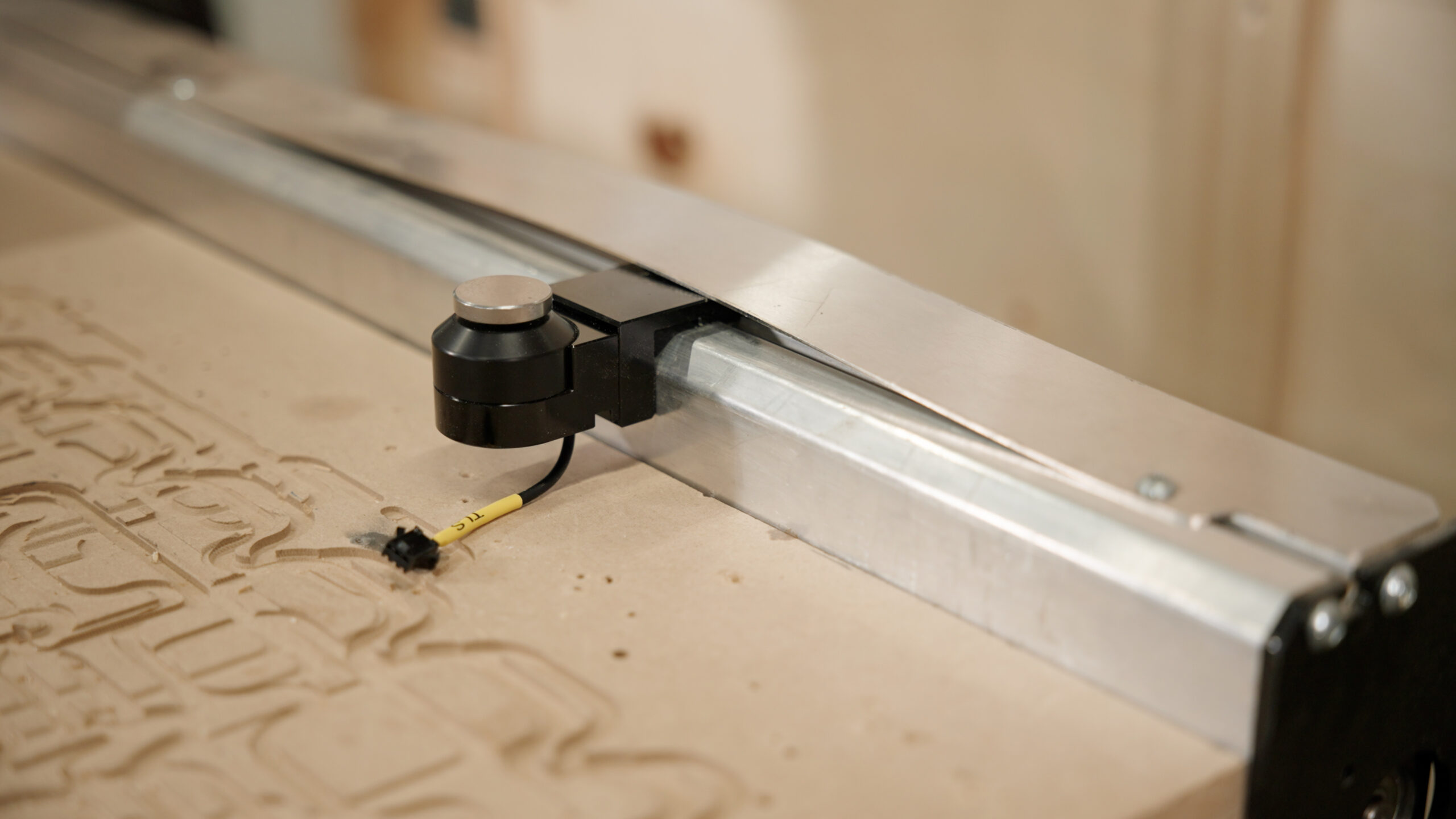
We recommend mounting onto the right Y-axis rail as it is clear of drag chains
-
Mount the TLS by inserting two (2) T-nuts into the T-slot of the right Y-axis rail. Then fasten the screws into the T-nuts, so that the TLS is hanging from the rail.
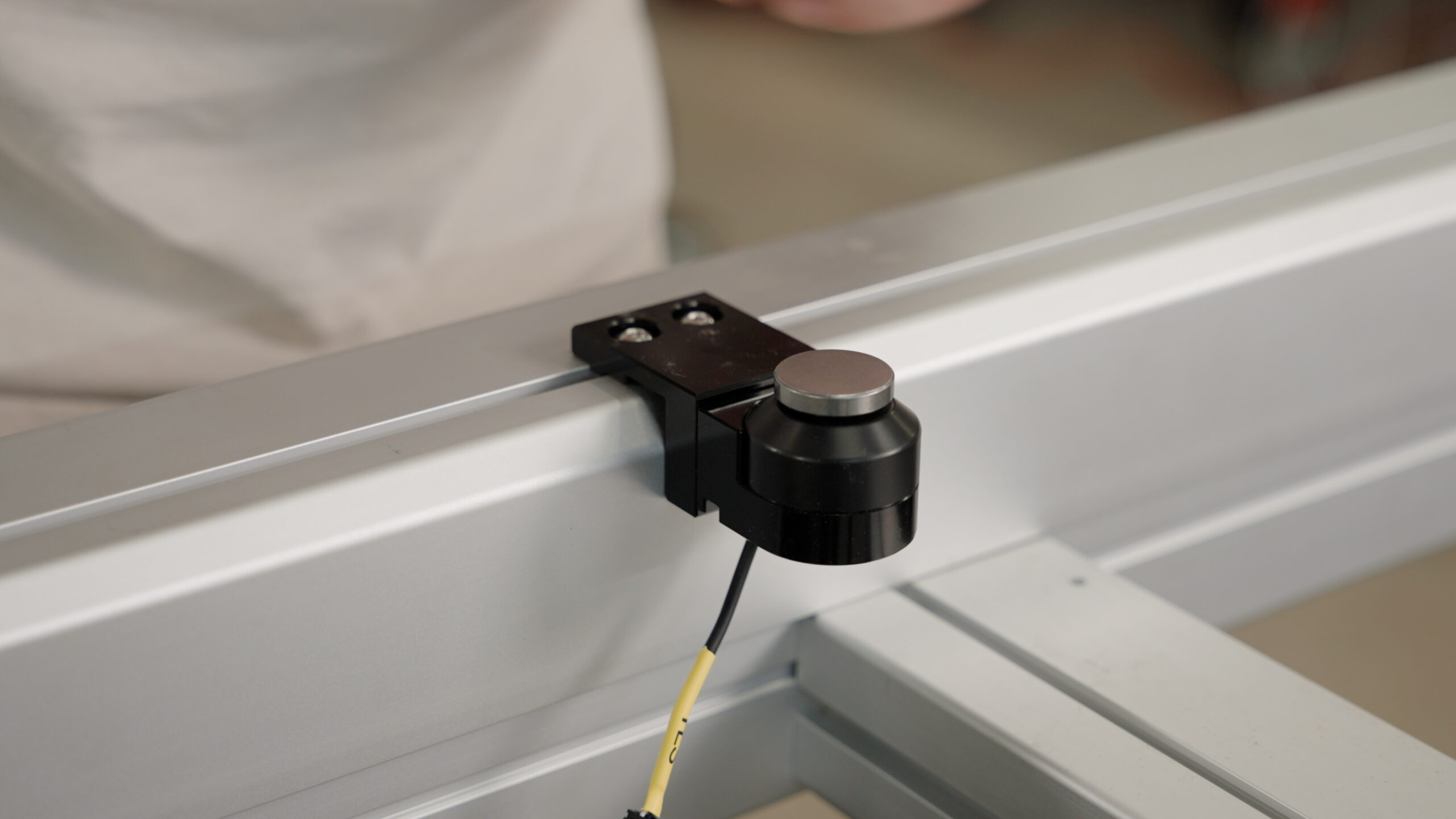
- For the AltMill MK1, you will need to temporarily disassemble the dust shield to mount the TLS. Afterwards, put the dust shield back on, over top of the TLS, to prevent premature wear of linear guides and ball screw
LongMill and other CNCs
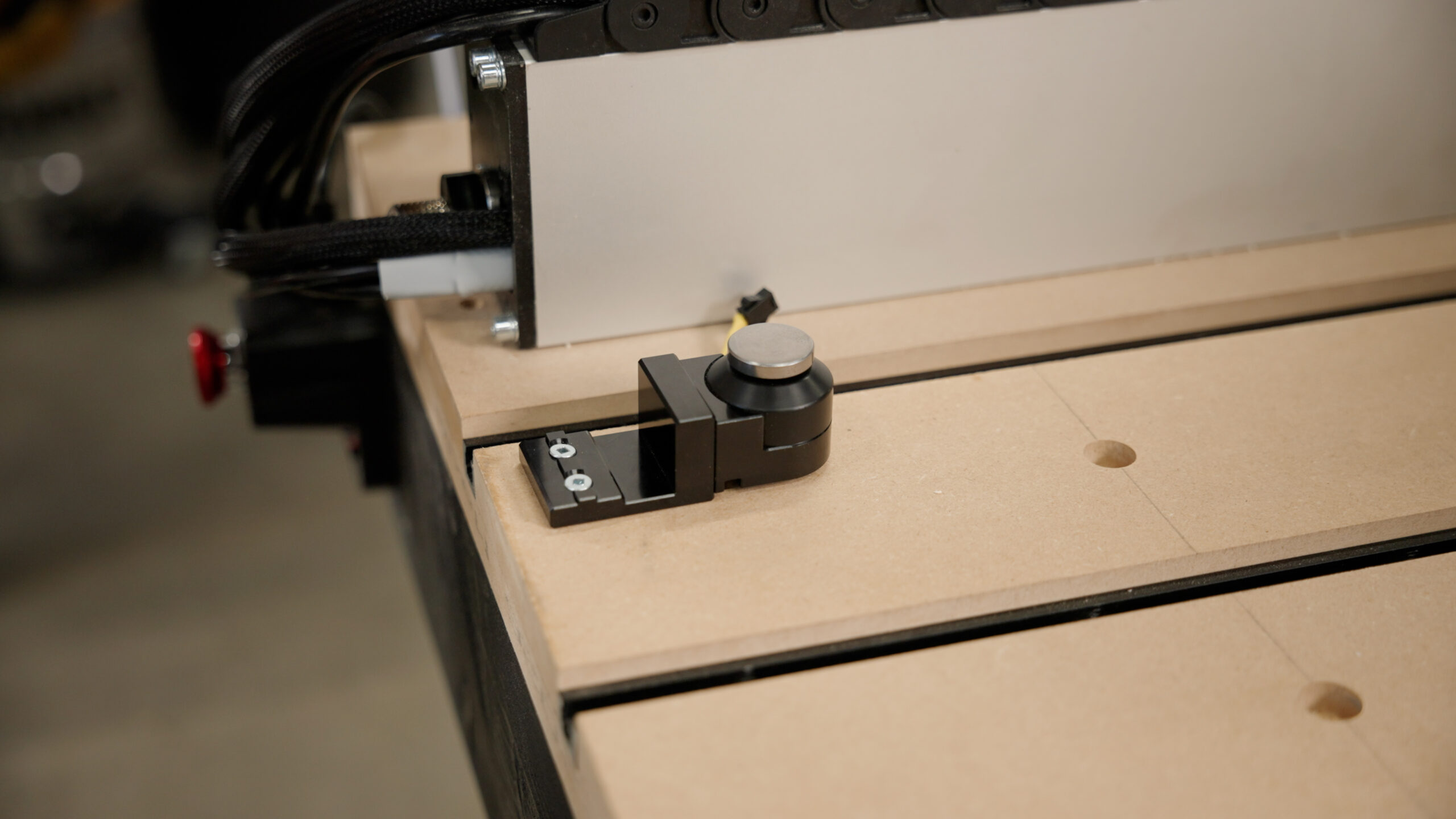
- Flip the TLS base so that it can sit flat, then screw it into the wasteboard of the desired location which can be reached by the router spindle, with two (2) wood screws.
Cable Connection
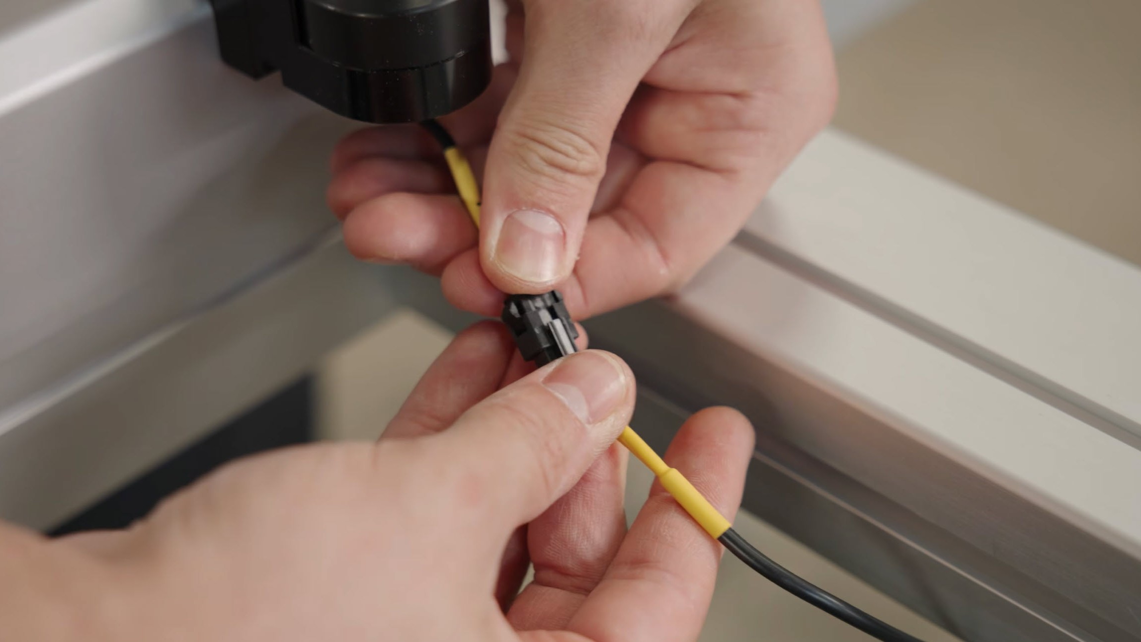
Attach the connector from the TLS to the TLS cable.
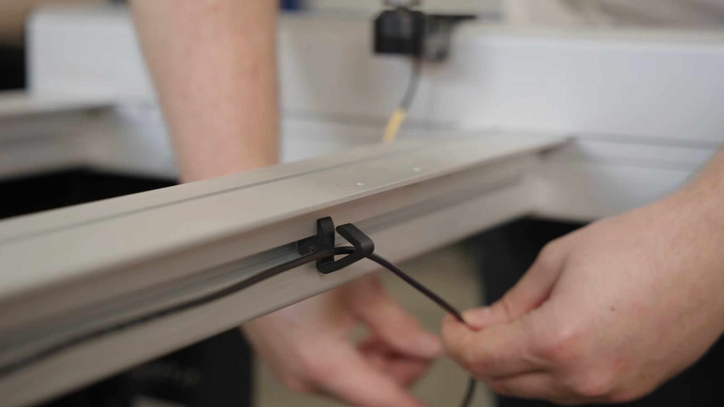
For AltMills: Since the TLS is mounted far away from the front, we will do some cable management. Install cable clips on the T-slots in the crossbeams, routing from the controller to the location of your TLS.
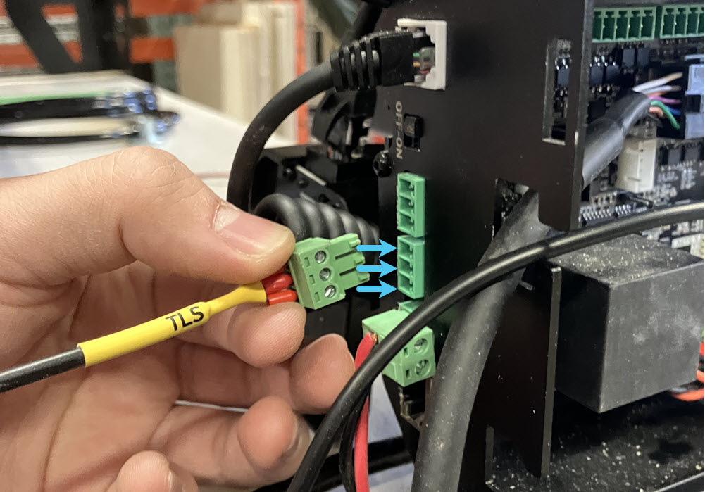
Finally, connect the other end of the TLS cable to the controller.
gSender Setup
gSender 1.6.3 or above
If you have gSender 1.6.3 or above, you can go through the setup automatically through the wizard.
-
Connect to gSender.
-
Jog the machine towards you and install your longest end mill into the spindle. This is to ensure there is enough clearance during tool changing.
-
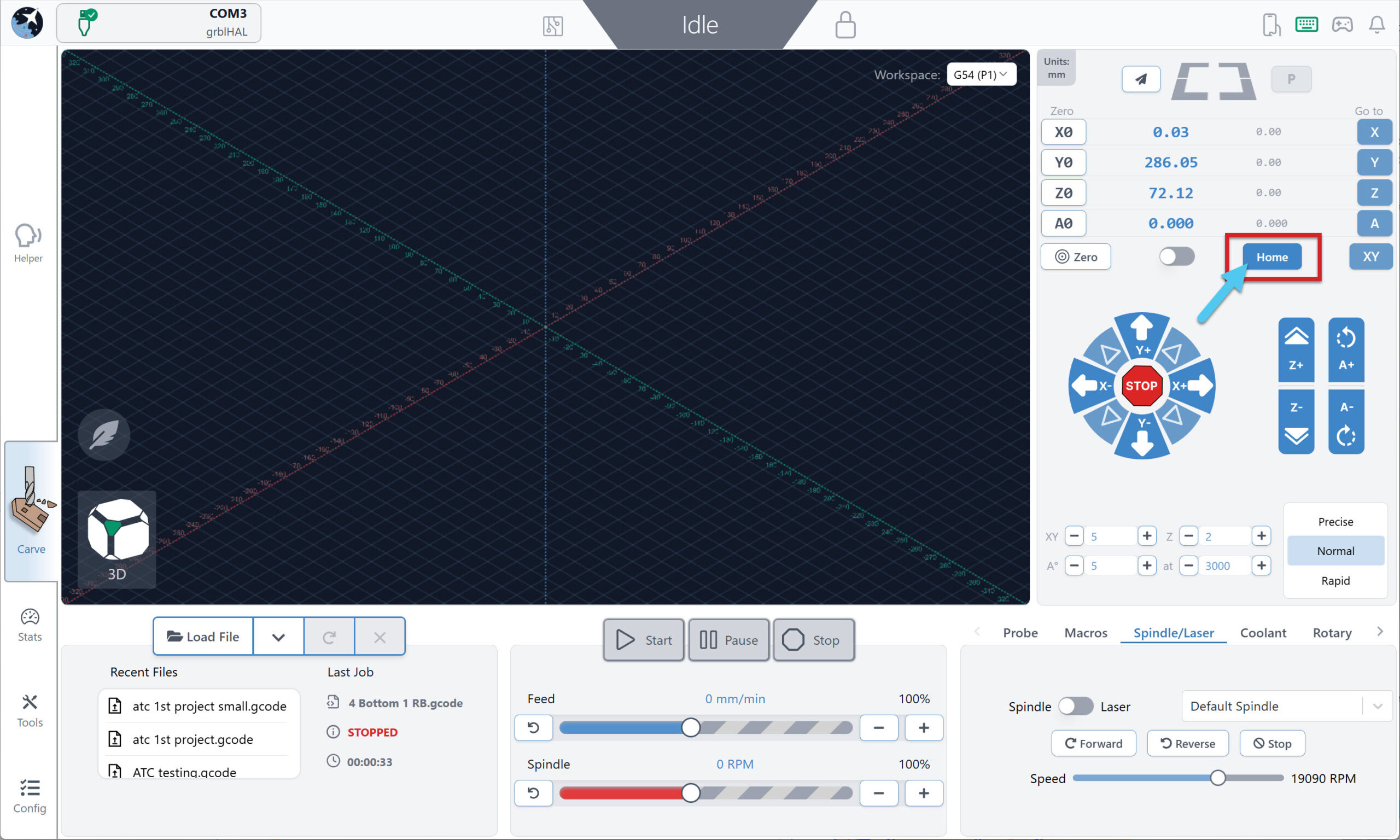
Home the machine. You must have limit switches installed to do homing, otherwise you cannot use the TLS.
-
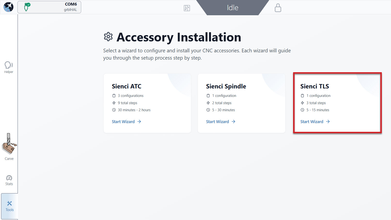
Go to Tools, Accessory Install, and select Sienci TLS.
-
Go through the setup wizard. A few tips:
-
Tool Change Options -> select Prompt for first tool
-
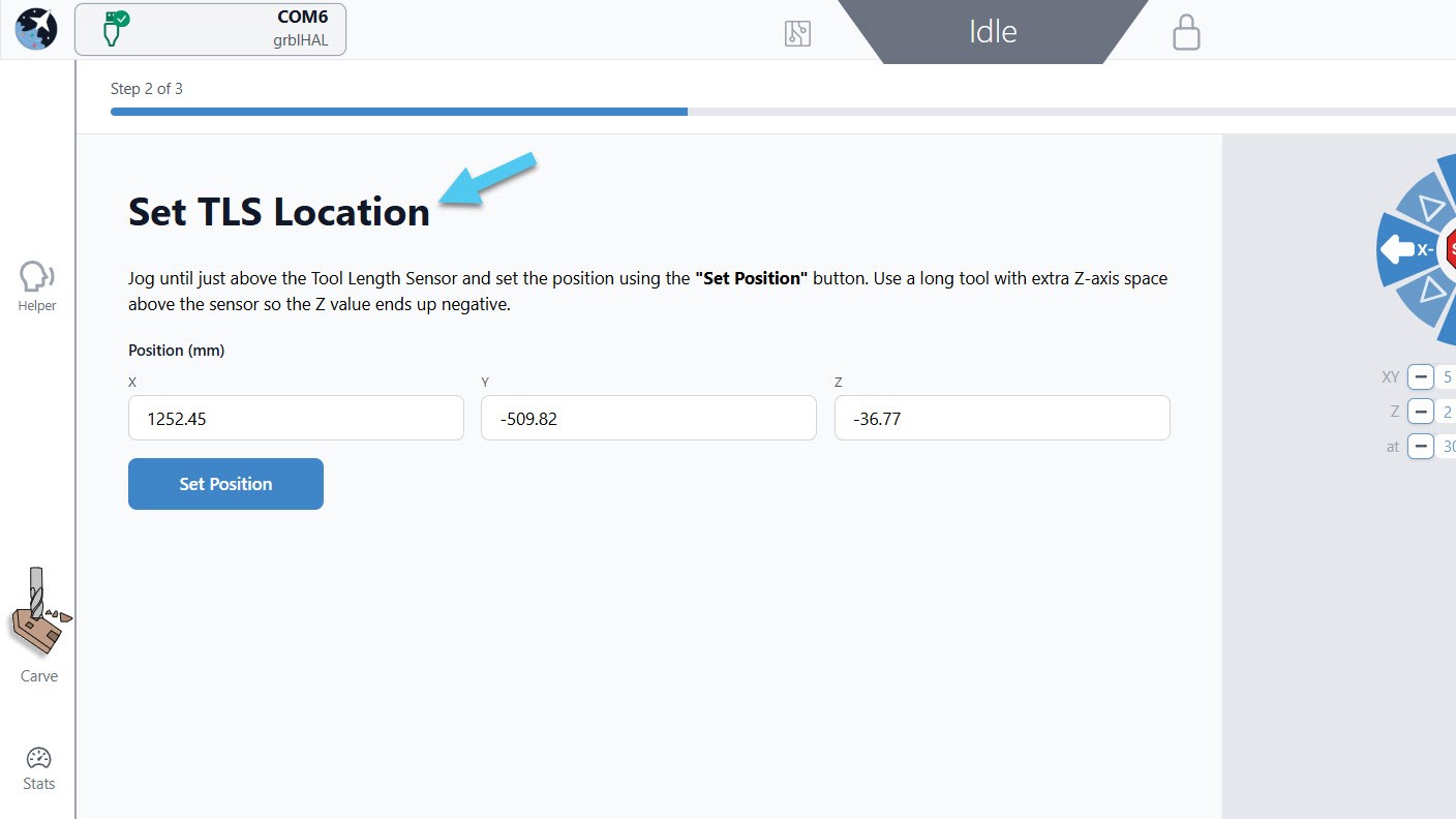
Set TLS Location -> jog the machine so the end mill is about 0.5-1″(10-20mm) above your TLS, centered. This ensures there is enough height for your tool when probing.
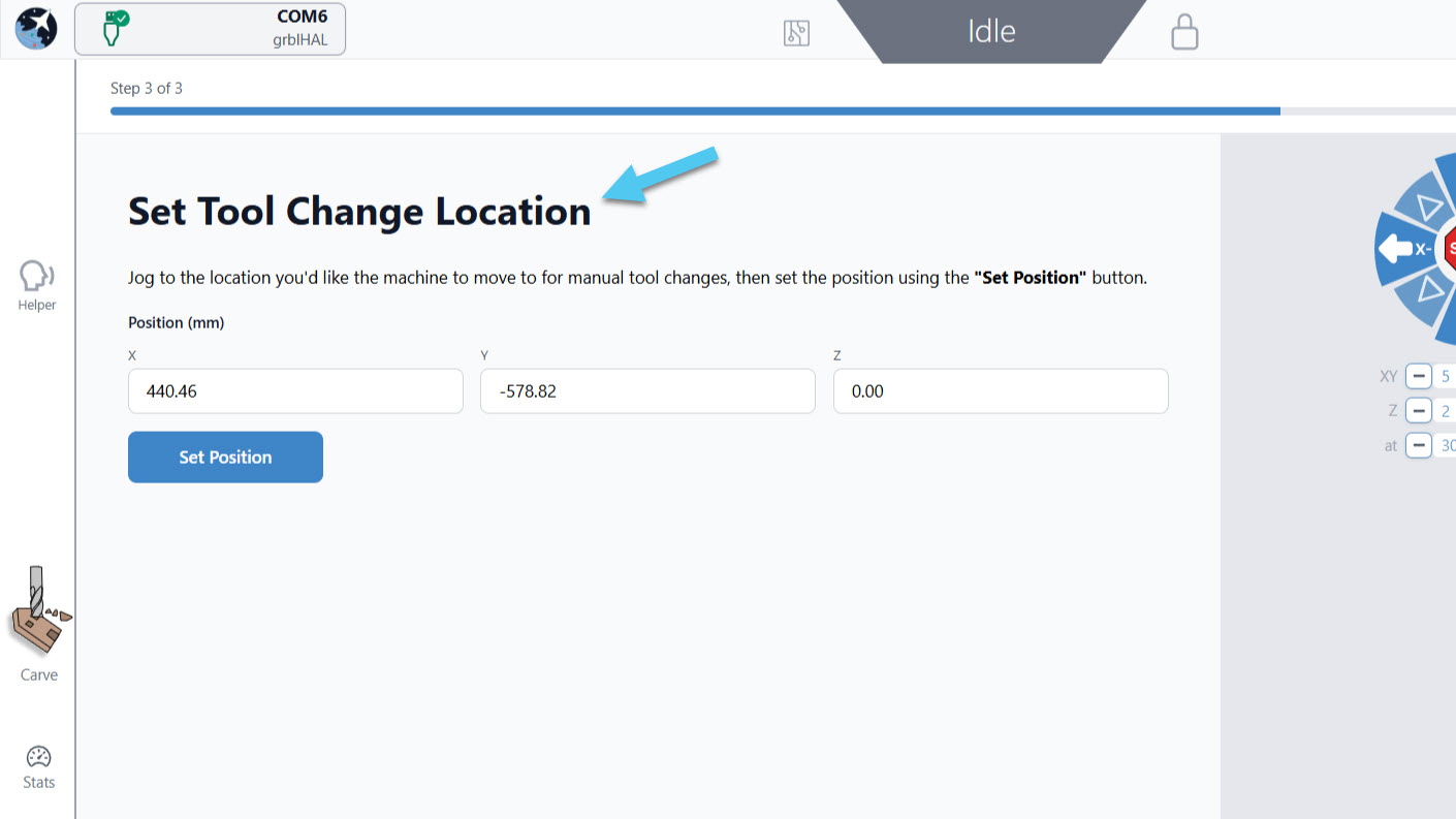
- Set Tool Change Location -> jog the machine towards you (e.g. front left). Then jog the Z-axis all the way up, to the top of the machine travel. This ensures you can access the tool easily while changing it out.
- Follow the remaining steps as prompted by the wizard.
-
gSender 1.6.2
If you have not upgraded gSender to 1.6.3. or above, you can still set up the TLS manually through the Config tab.
-
Make sure you have gSender 1.6.2 as older versions have limited TLS support. Detailed instructions can be found in this article.
-
Connect to gSender.
-
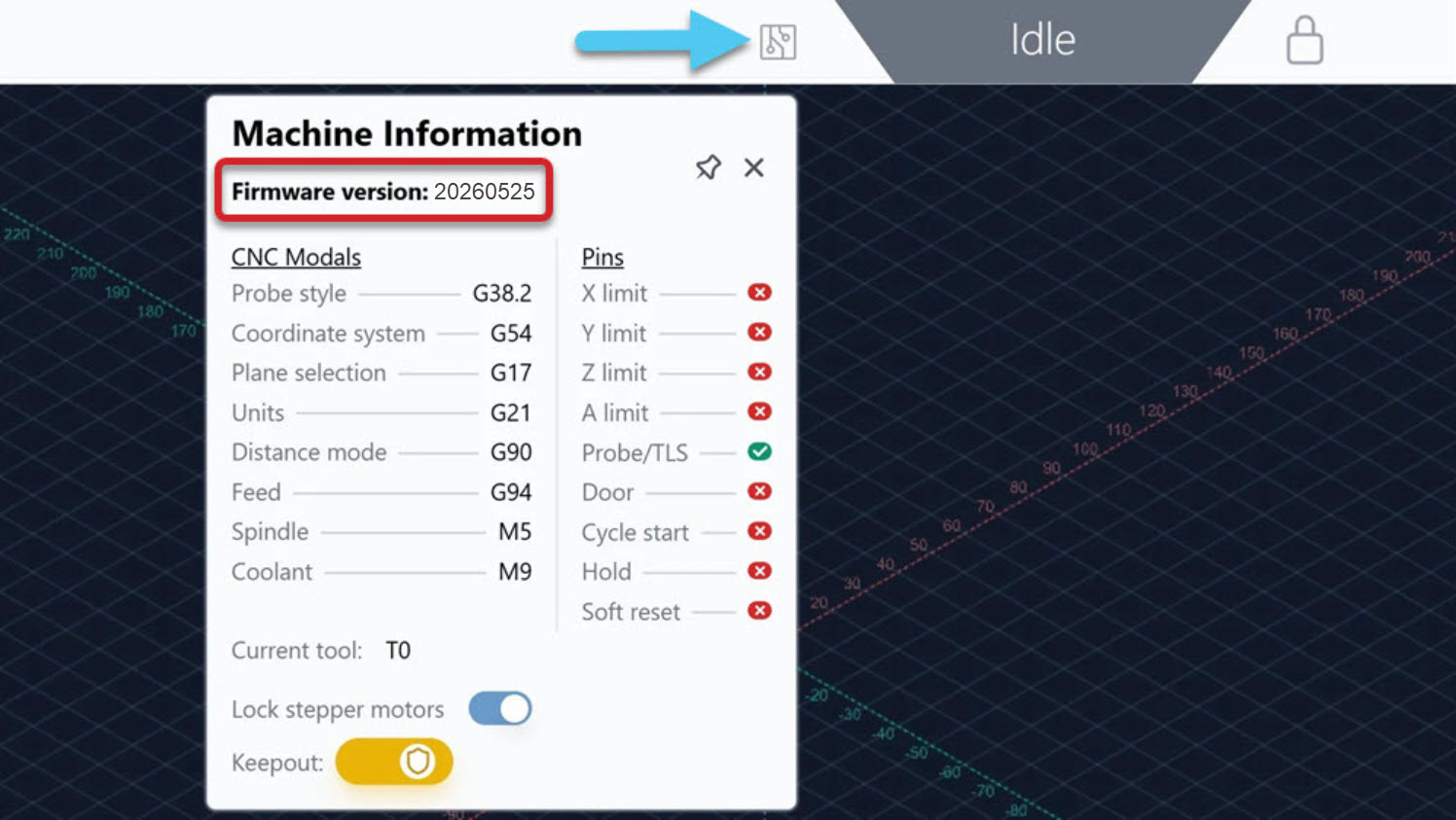
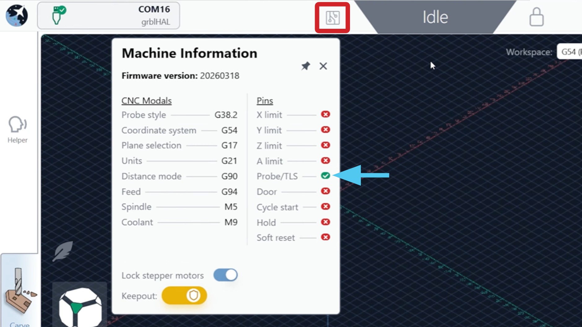
Check your controller firmware version by clicking on the machine information (circuit board) icon. Write it down so you can refer to it later – it affects a setting we need to change.
-
Jog the machine towards you and install your longest end mill into the spindle. This is to ensure there is enough clearance during tool changing.
-
Home the machine. You must have limit switches installed to do homing, otherwise you cannot use the TLS.
-
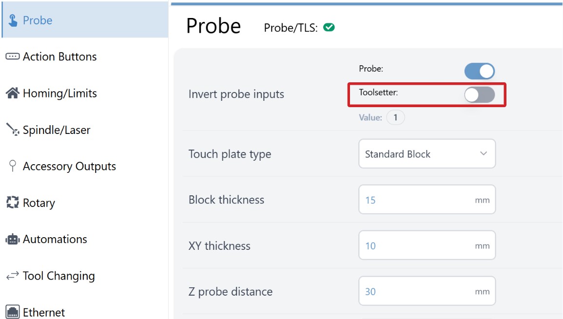
Go to Config, and select the Probe tab. We will change the setting Invert probe inputs ($6) based on the controller firmware version.
Firmware that starts with 2026 or higher (e.g. 20260525, 20260318)
- Probe ON
- Toolsetter ON
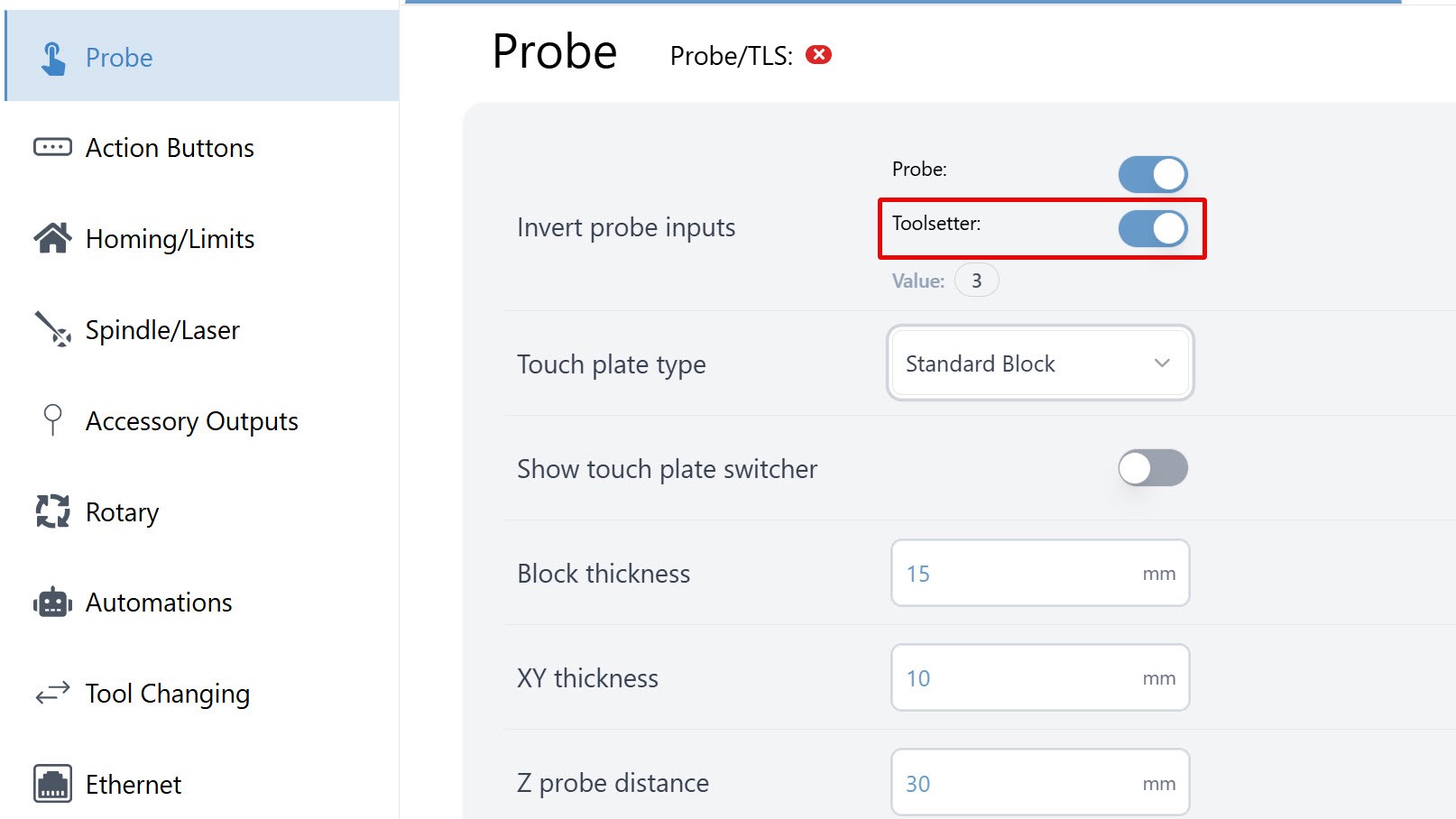
All other firmware versions
- Probe ON
- Toolsetter OFF
-
Go back to the main Carve screen. Jog the machine so the end mill is positioned over the center of the TLS, slightly above the metal button, about 0.5-1″ (10-20mm).
-
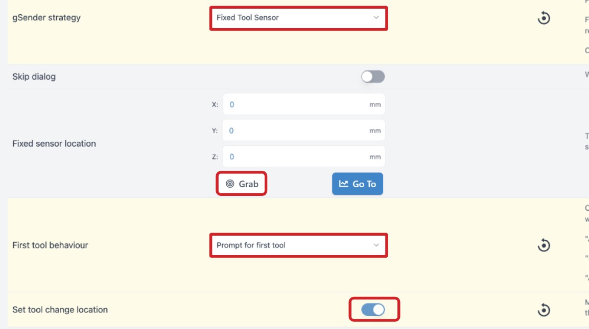
Go back to Config. Under the Tool Changing tab, adjust the following settings:
- gSender strategy
- Select “Fixed Tool Sensor”
- Fixed sensor location
- Press the Grab button
- First tool behaviour
- “Prompt for first tool”
- Set tool change location
- Toggle ON
- gSender strategy
-
Press Apply Settings.
-
Go back to the main Carve screen. Jog the machine to a place where you can change out your end mill safely and easily, like at the front left of your machine. Then jog all the way up on the Z-axis – this ensures you can access the tool easily while changing it out.
-
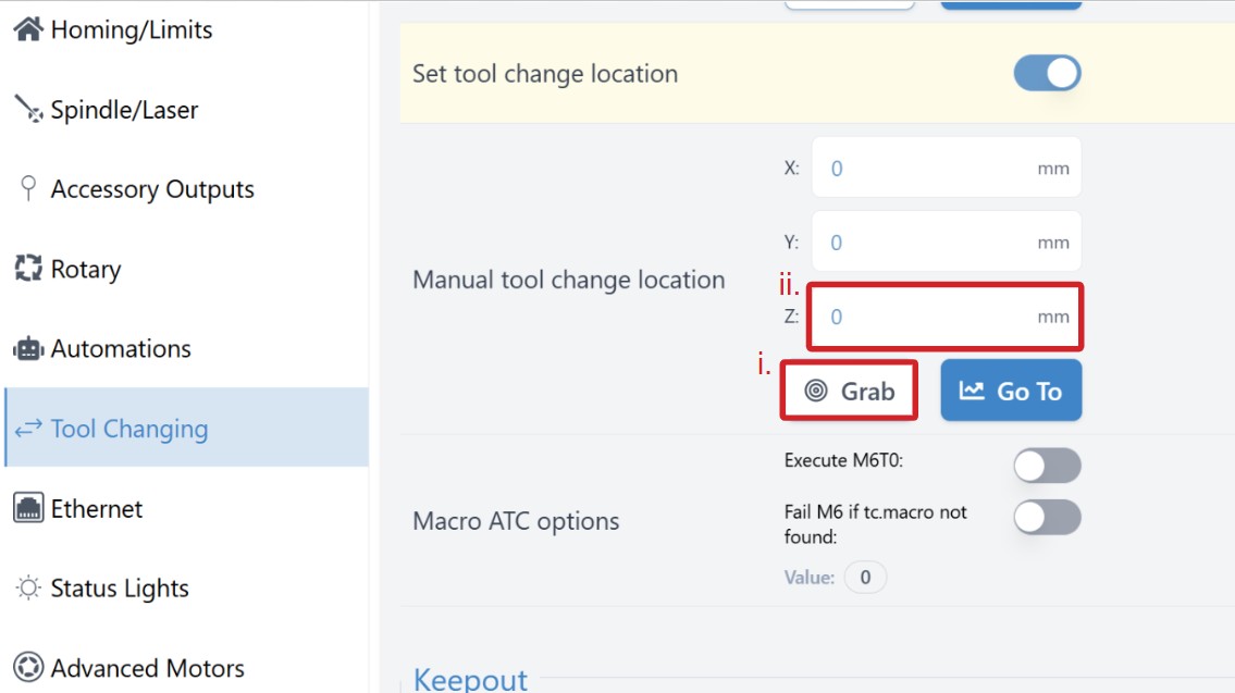
In Config, navigate back to Tool Changing tab, then find the Manual tool change location
- Press the Grab button
-
Press Apply Settings.
-
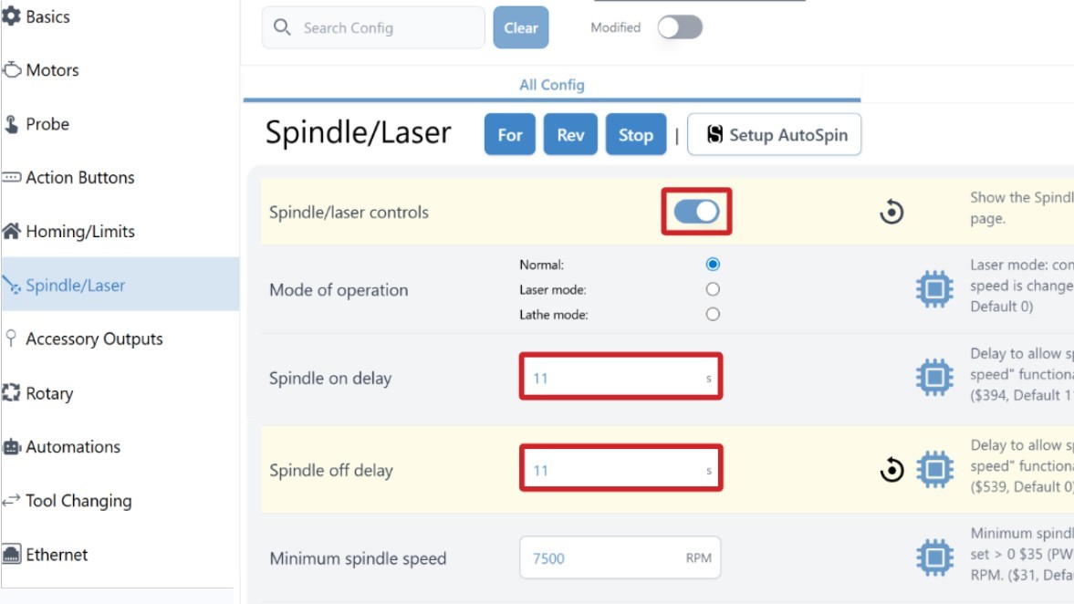
In Config, go to the Spindle/Laser tab and adjust these settings:
- Spindle/laser controls
- Toggle ON
- Spindle on delay ($394)
- 11
- Spindle off delay ($539)
- 11
- Spindle/laser controls
-
Press Apply Settings, then turn OFF/ON the controller.
-
Re-connect to gSender.
⚠️ Note that if you adjust your spindle height anytime after the TLS setup wizard, you must re-run the wizard or else the TLS won't work properly.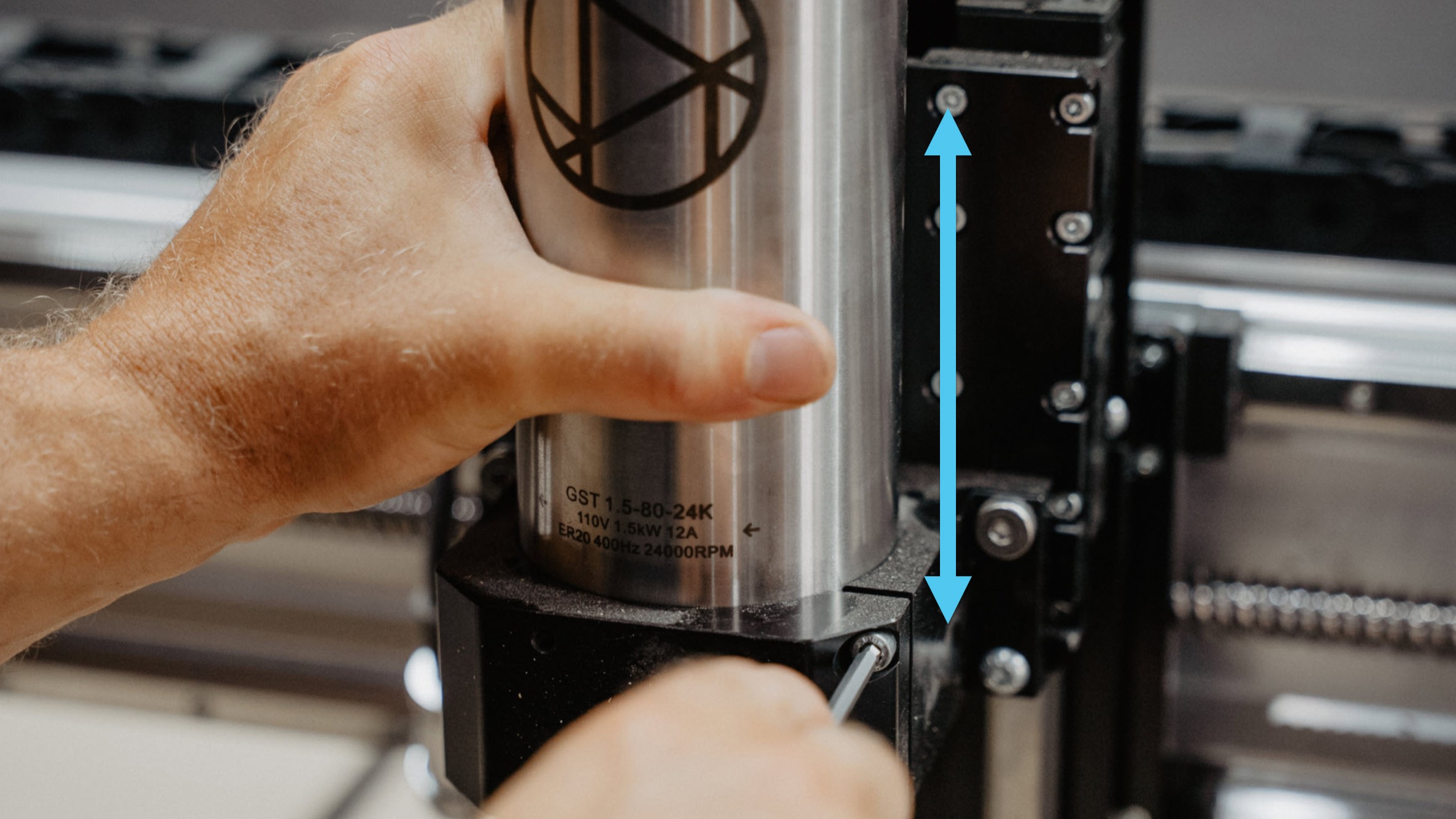
Testing
To make sure that the TLS is working as expected, press down on the TLS.
- On gSender, select Machine Info (circuit board icon) and you should see the Probe signal turn green.
- On the controller, the TLS orange light will turn OFF.
❗Note that this light will stay OFF if TLS is disconnected

Export g-code on CAM
On your CAM program, you will need to adjust your g-code export settings to allow you to run tool changes. This will involve injecting M6 and T# commands between each toolpath, so that all the toolpaths can be saved onto one g-code file.
Vectric
The default grbl post-processor does not support tool changing, you will need to use the Sienci Labs TC post-processor.
-
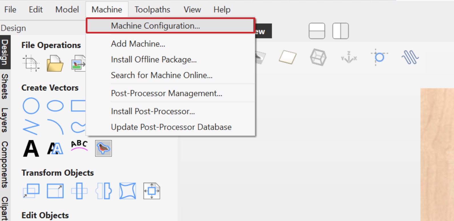
Under Machine, select Machine Configuration.
-
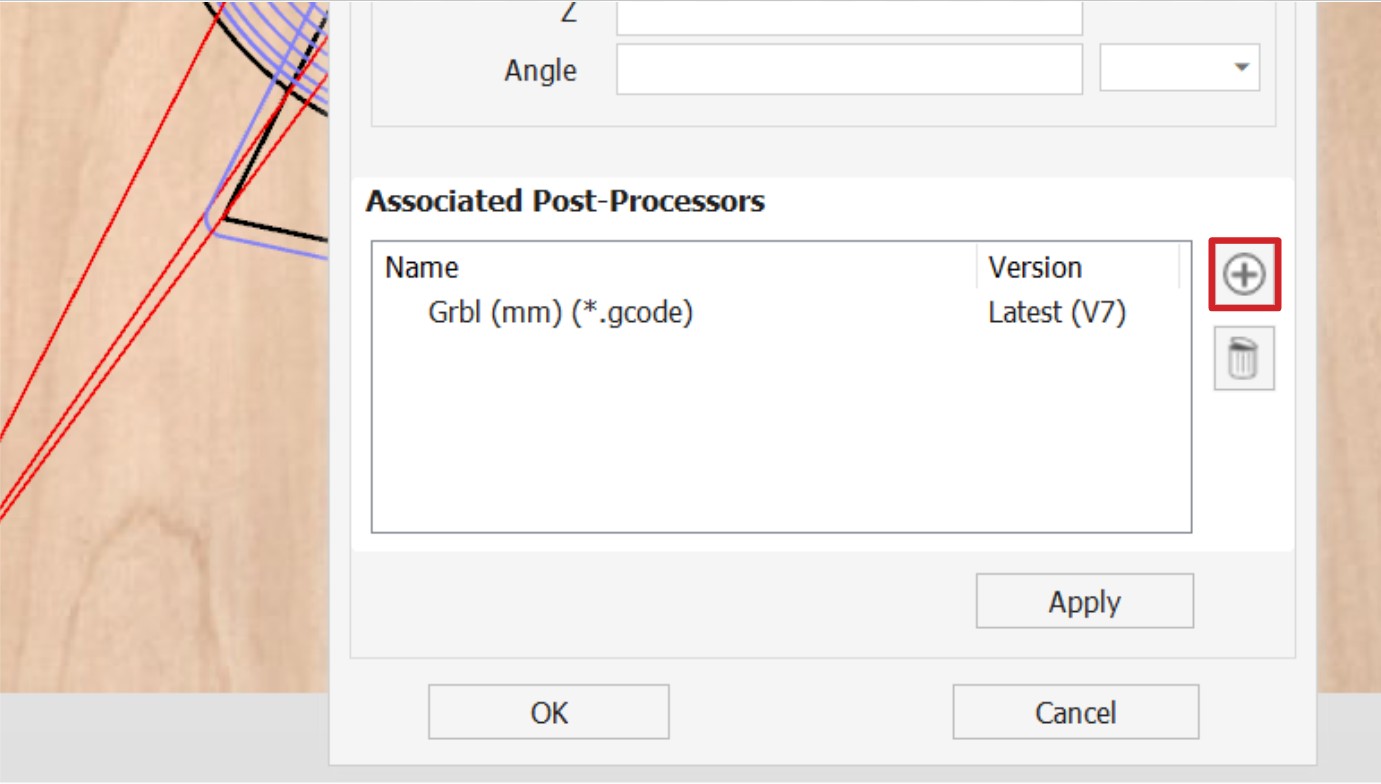
Add a new post-processor using the + button.
-
There are two Sienci Labs post-processors available, select the Sienci Labs TC for regular 3-axis milling. Otherwise you can come back to this window to add the Sienci Labs Vortex TC, if you have a Vortex.
i. If you cannot see the post-processor, press the cloud with arrow button to automatically download the latest ones.
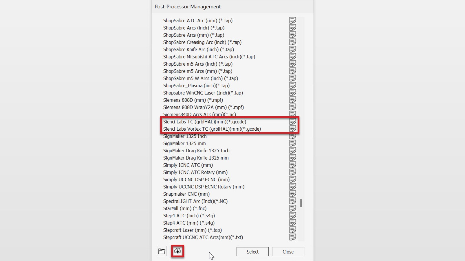
ii. If you still cannot see them, you can download and install them on your own. Instructions on installation can be found on Vectric’s website.
-
Finally, when saving your toolpaths to export as g-code, select Visible toolpaths to one file.
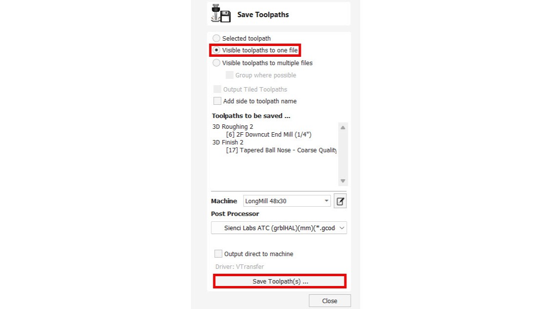
❗If you run into an error while exporting, it may be because you have duplicated tool numbers. Since all this g-code is in one file, you must have unique tool numbers (T#) assigned to each toolpath. On Vectric, for each toolpath, go to tool library and replace the tool number with different whole numbers (e.g. 1, 2, 5, 12), then try saving again. Or you can do it manually - open your existing g-code file in a text-editing program (i.e. Notepad) and change every T# to be unique.Carveco
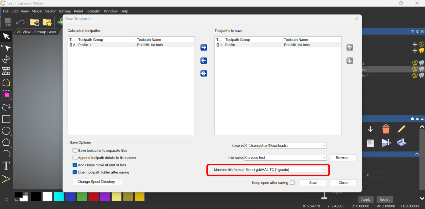
Carveco’s default grbl post-processor does not support tool changing.
You will need to download and install this post-processor.
Fusion 360
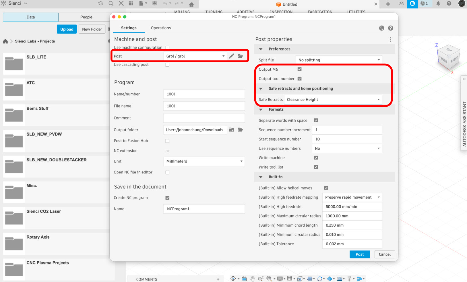
⚠️ Please note tool changing is only available with a Fusion360 subscription.
Fusion has the ability to toggle on tool changing g-code. When exporting the g-code, adjust the following settings.
-
Output M6: Yes
-
Output Tool Number: Yes
Run a Job on gSender
-
Once the g-code has been saved to your computer, open gSender and connect to your machine.
-
Home the machine.
-
Load the g-code file.
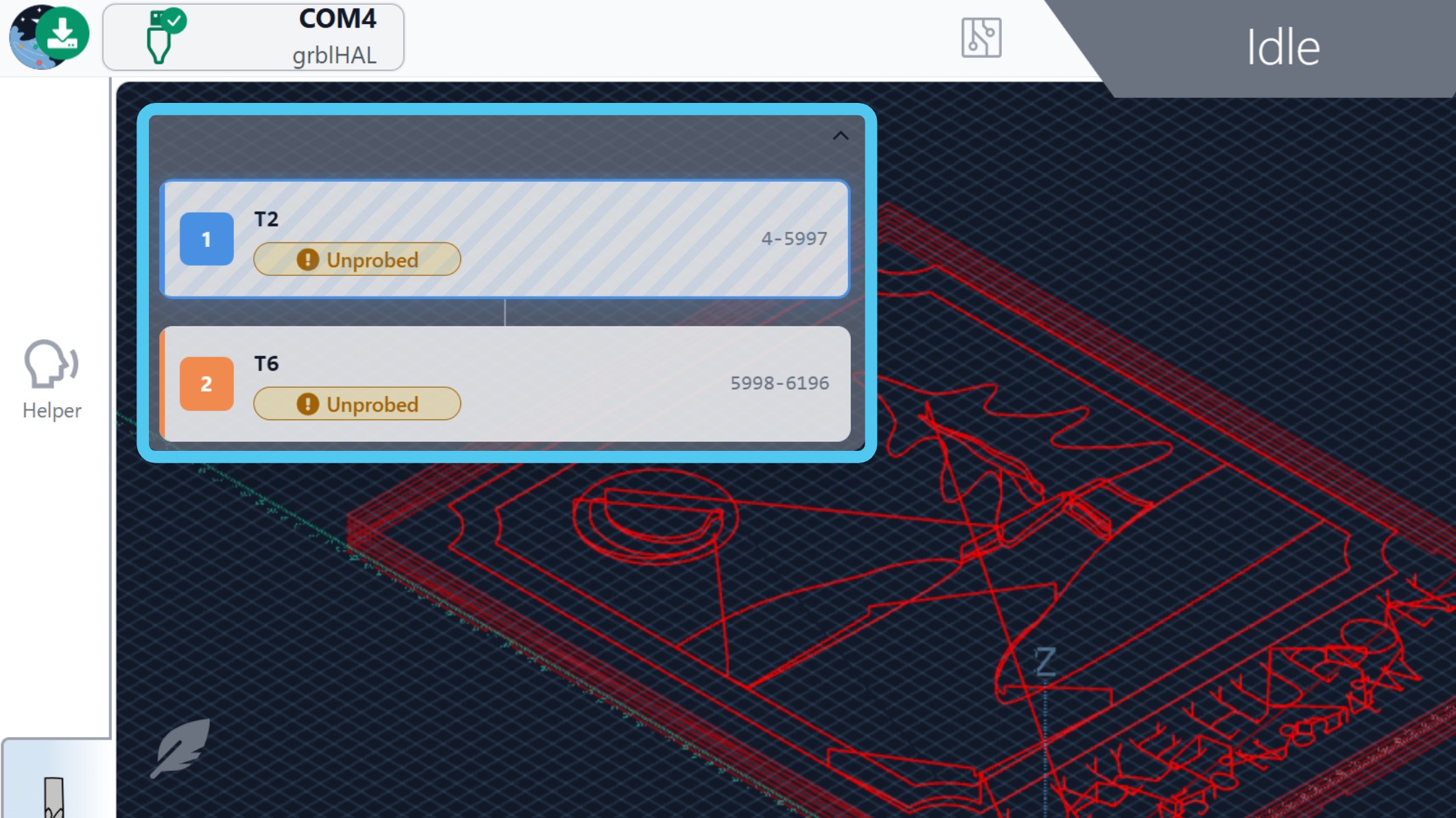
You should see the Tool Timeline on the left side which shows the different toolpaths.
-
Install the end mill you are starting your job with.
-
With your stock material secured on the wasteboard, set your X, Y Z zeros by either using a touch plate or manually.
-
Press Start to run your job! The tool change wizard will pop up, you will be prompted to either probe the tool length or do a full tool change.
Select the Only probe tool length option – this causes the machine to probe the TLS with your installed end mill.
Finally it will start your job. The spindle will spin up, and the machine will start cutting!
⚠️ Make sure the AutoZero touch plate is put away so that it does not trigger. Otherwise it will cause a false reading that will affect the TLS operation.The spindle and machine will pause at each tool change, as the wizard guides you through each step on-screen.