Wiring
Y-axis Cable Mounting
Grab three cable hanger clips, install these into the T-slot at the rear of the table, slotting these into the T-slot and twisting them clockwise to secure each clip.
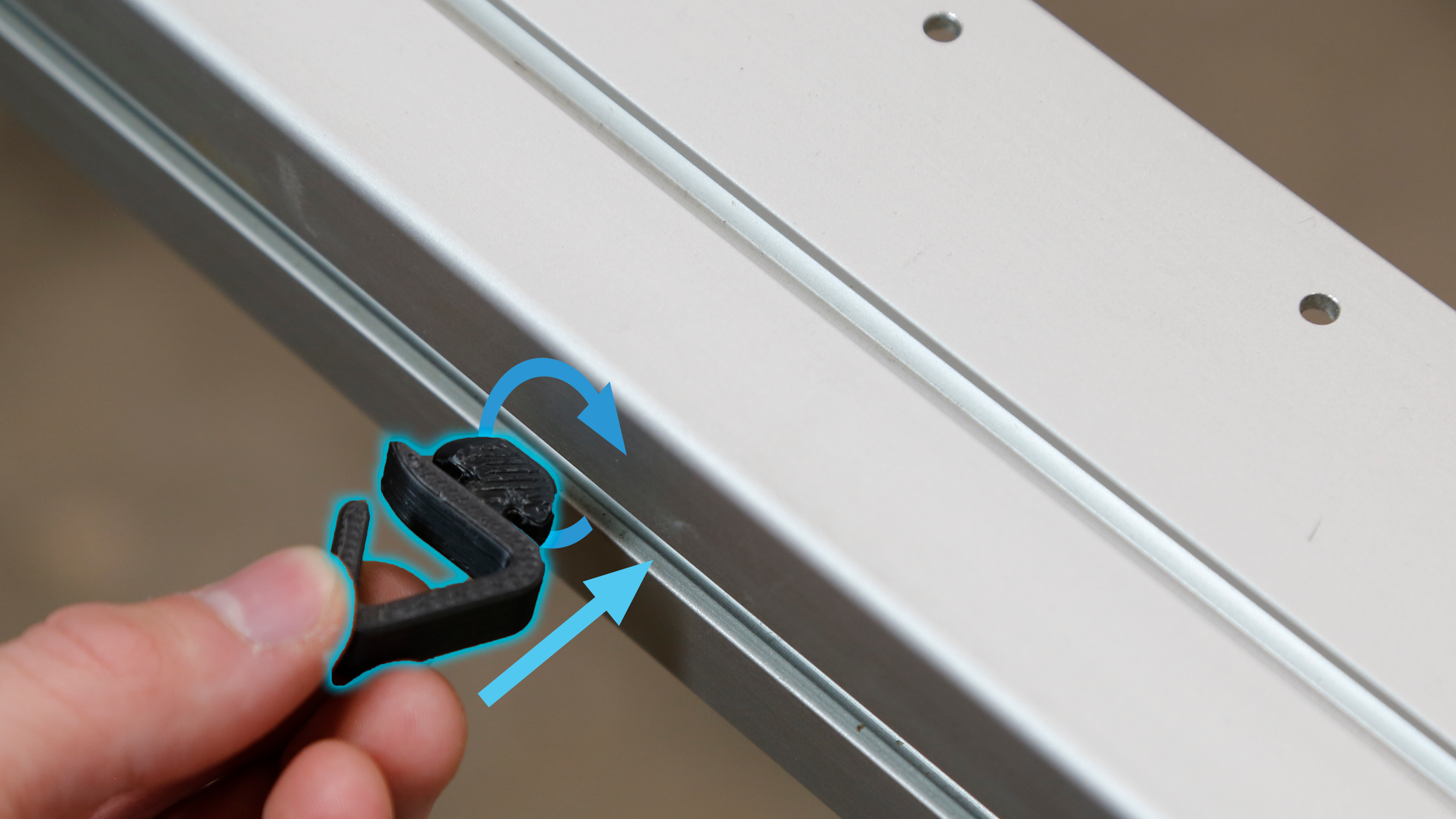
Hanger clip installation
Space these cable hanger clips out evenly across the rear of the crossbeam.
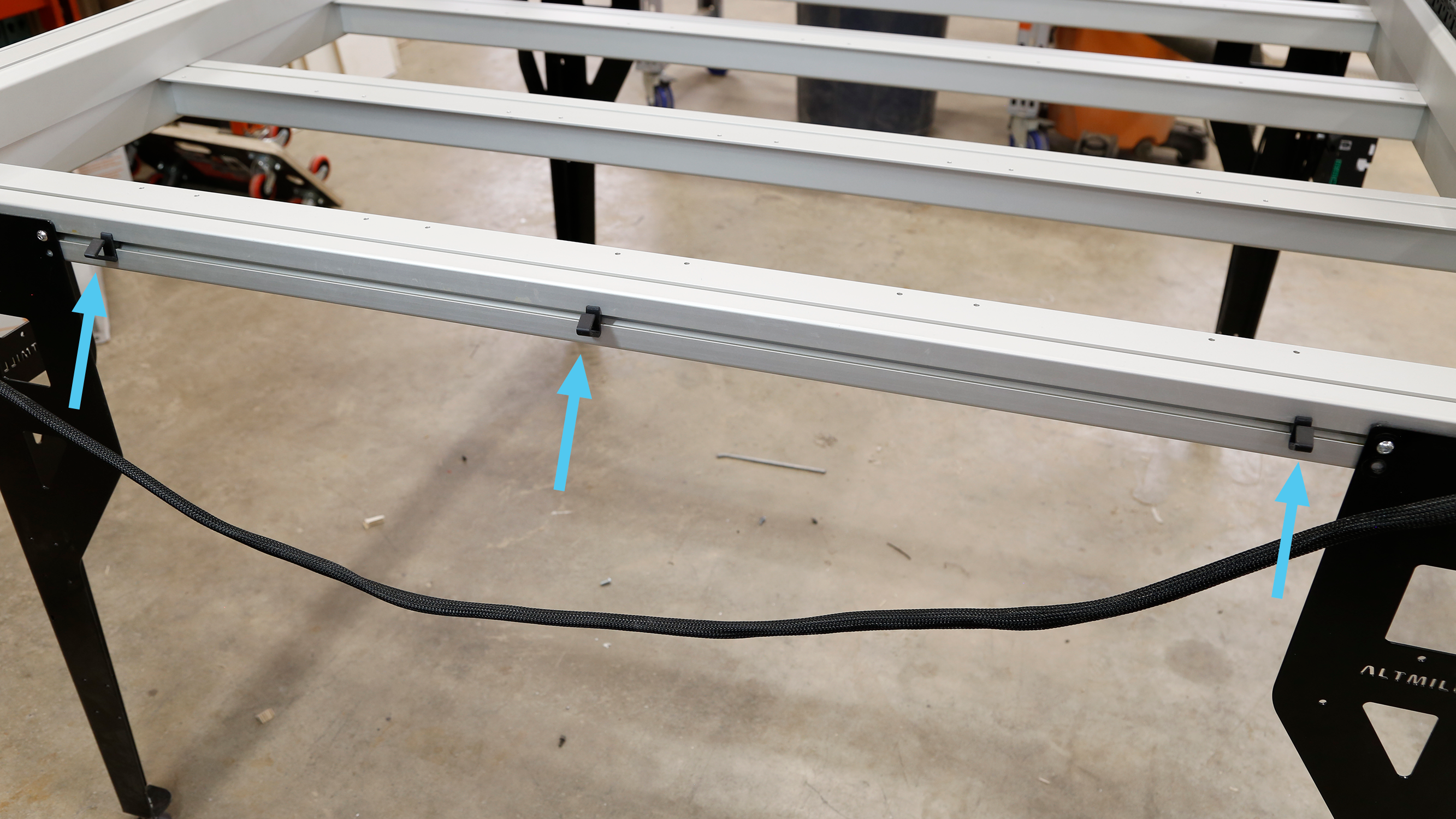
Location of hanger clips
Slide the Y2 motor cable through the opening at the top of the cable hanger clip to secure the cable in place. Leave both Y-axis motor cables unplugged from the motors, as these will be plugged in later.
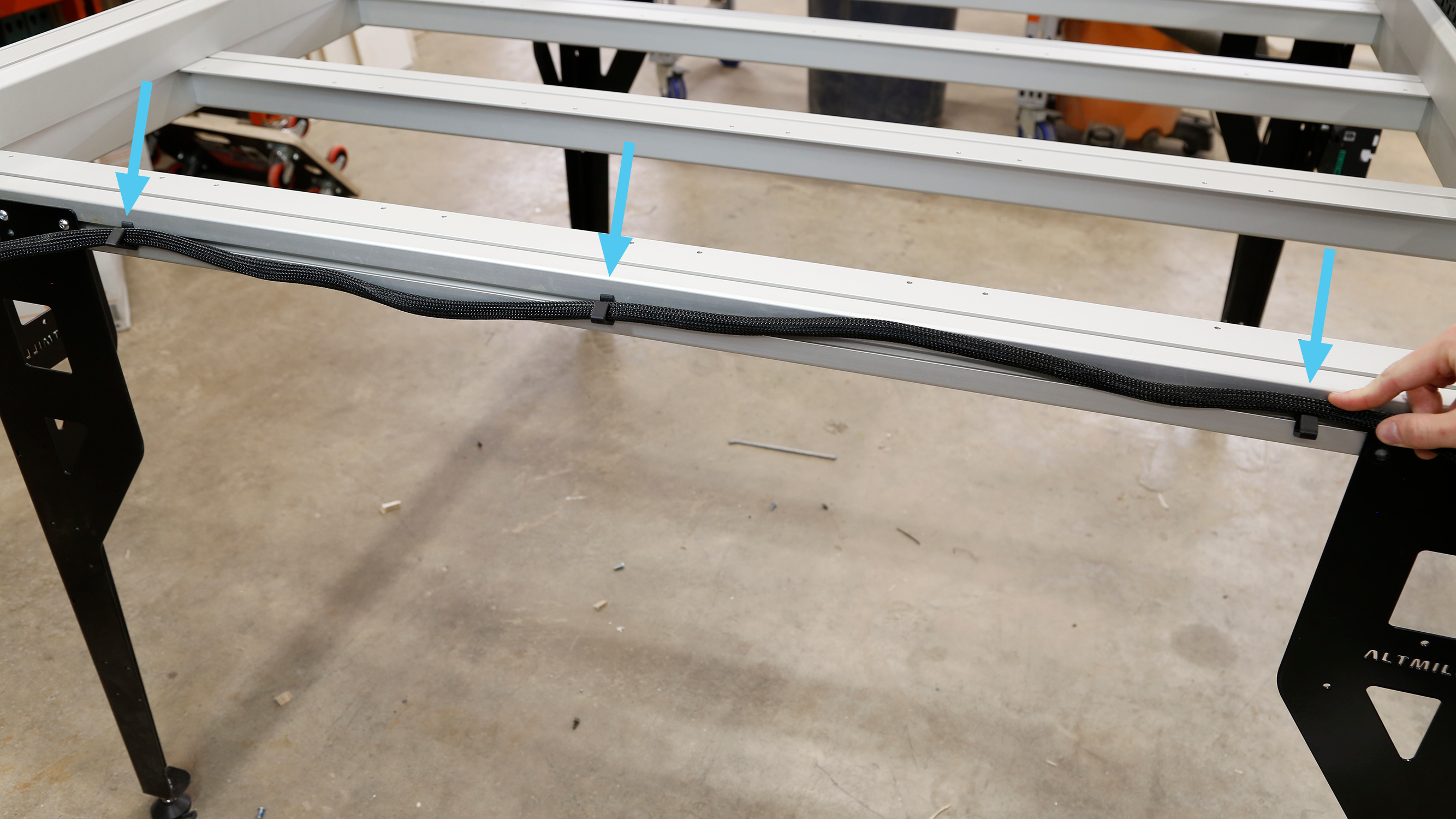
Securing Y2 motor cable in hanger clips
Spindle and VFD Installation
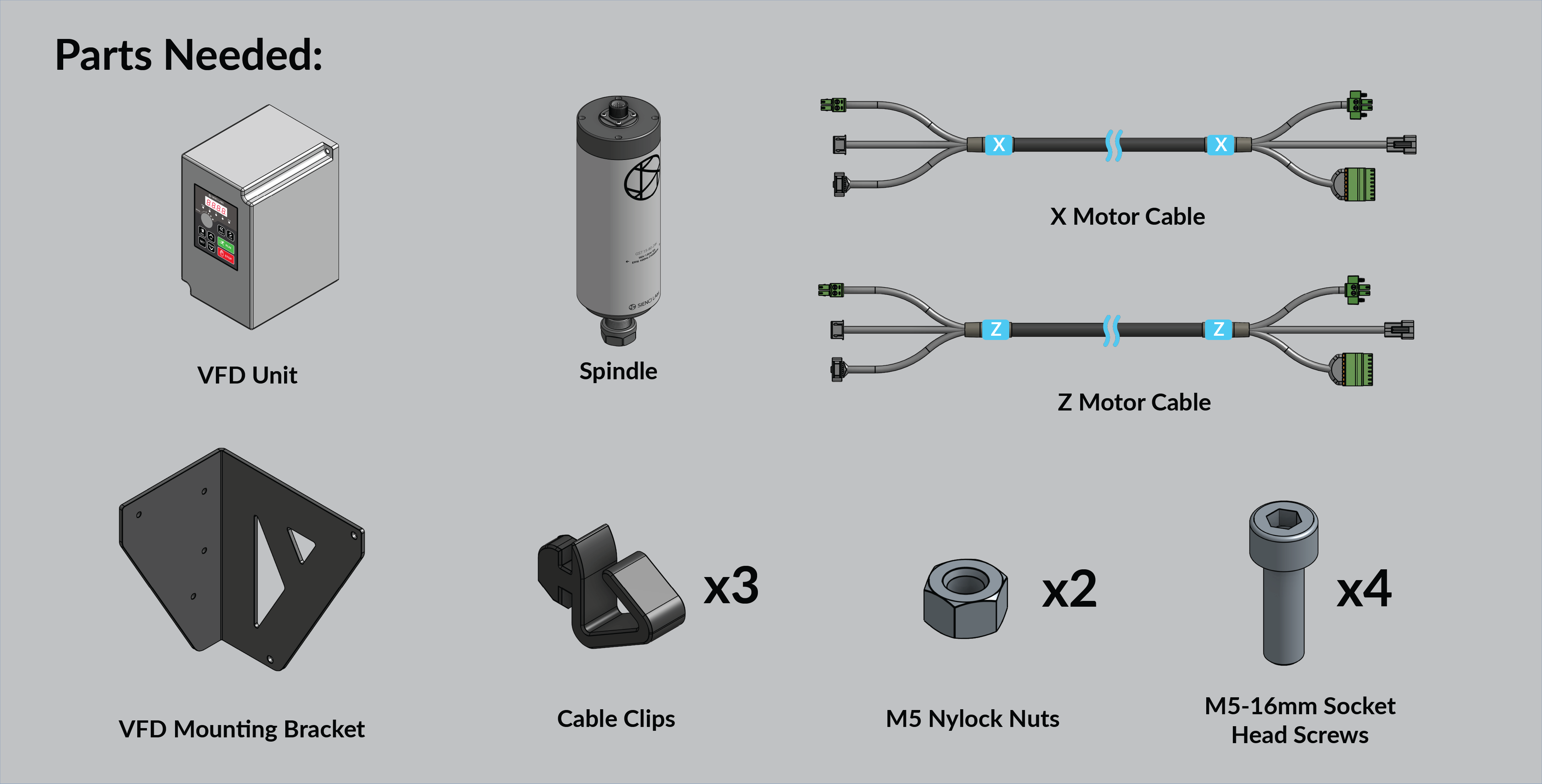
If you purchased the Sienci Labs Spindle Kit, then open the box and take out the spindle and VFD unit. Otherwise, if you are installing your own 80mm spindle, have it ready on hand along with any other accessories.
On the VFD unit, align the VFD mounting bracket with the holes as shown. Using two (2) M5-16mm socket head cap screws and two M5 nylock nuts, secure the VFD unit onto the bracket. Use the included wrench to hold the M5 nuts in place.
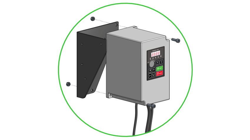
Aligning holes between VFD unit and mounting bracket
Mount the VFD unit onto the inner walls of the front left table leg, orienting it so that the control panel is accessible from the cutout on the leg. Use two (2) M5-16mm socket head cap screws to secure the VFD bracket onto the leg.
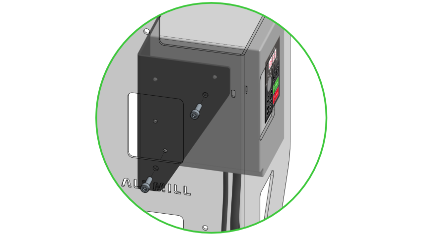
Fastening VFD bracket onto table leg with socket head cap screws
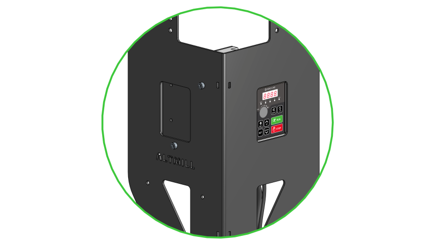
VFD unit correctly mounted, control panel accessible through leg cutout
Grab the spindle cable from the bottom of the VFD unit, this will be the longest cable. Route this cable around the back of the table leg, wrapping around to the front side of the machine, then swing this cable over the top of the table, and under the X-axis rail. Leave this bundle resting on a crossbeam for now.
It is important that this cable is routed in this path so that it can be run through the drag chains later on
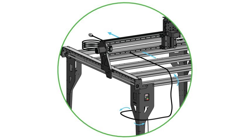
Initial spindle cable routing
Ensure the two screws which clamp the spindle mount are loosened fully, so that the spindle mount is fully open.
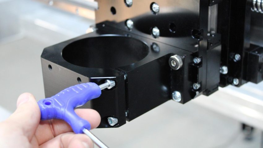
Loosening clamping screws on spindle mount
Grab the spindle and the foam packaging it came in. Place the spindle through the top of the spindle mount, and use the foam packaging to rest the end of the spindle over the front crossbeam.
Adjust the height of the spindle mount by turning the Z-axis ball screw, so that the end of the spindle extends past the bottom of the mount by about 4.5”. This can also be adjusted later depending on your setup. Tighten the two clamping screws using the 4mm hex key to lock the spindle in place. Go back and forth between tightening both screws to ensure even clamping force.
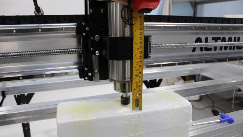
Spindle mount height adjustment
Grab the end of the spindle cable and bring it over the X-axis, guiding it to the top of the spindle. Match the connectors before securely plugging the connectors together.
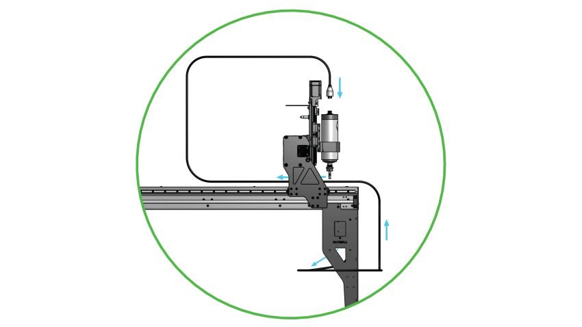
Side view showing complete cable routing path
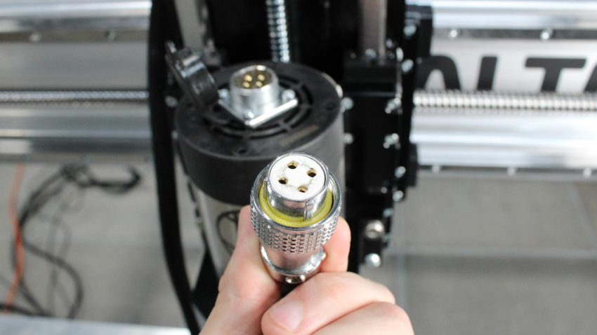
Pattern of connector holes on spindle cable plug
Thread the connectors together by rotating the collar on the cable side clockwise. Pull the connector to check they are properly secured.
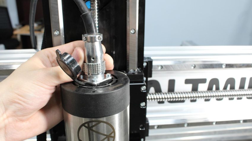
Spindle cable collar threaded onto spindle connector
X and Z-axis Cable Mounting
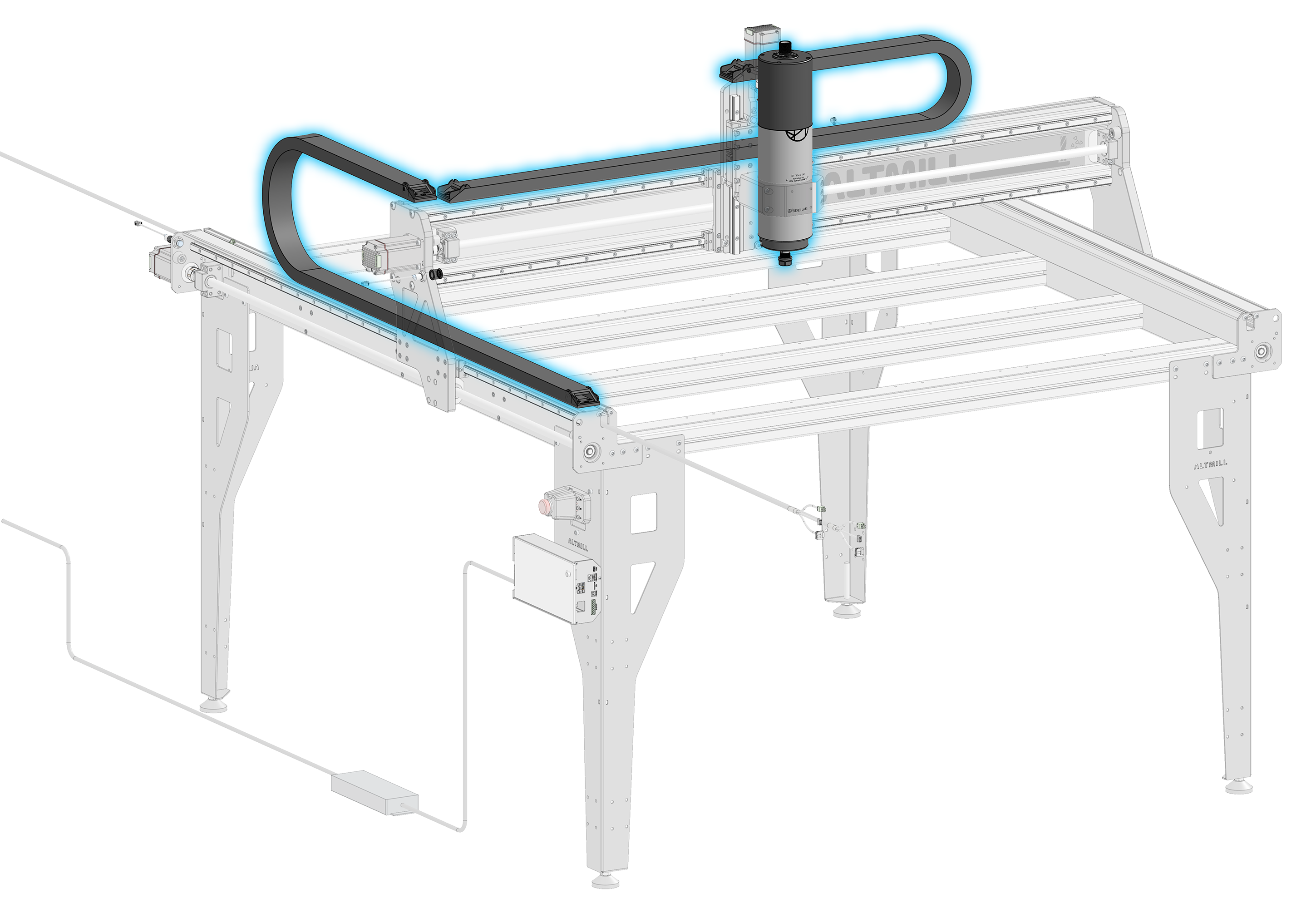
Place one drag chain on the X rail, and run the Z-axis motor cable and spindle cable through it. The cables should enter through the right side of the machine, and exit from the left side.
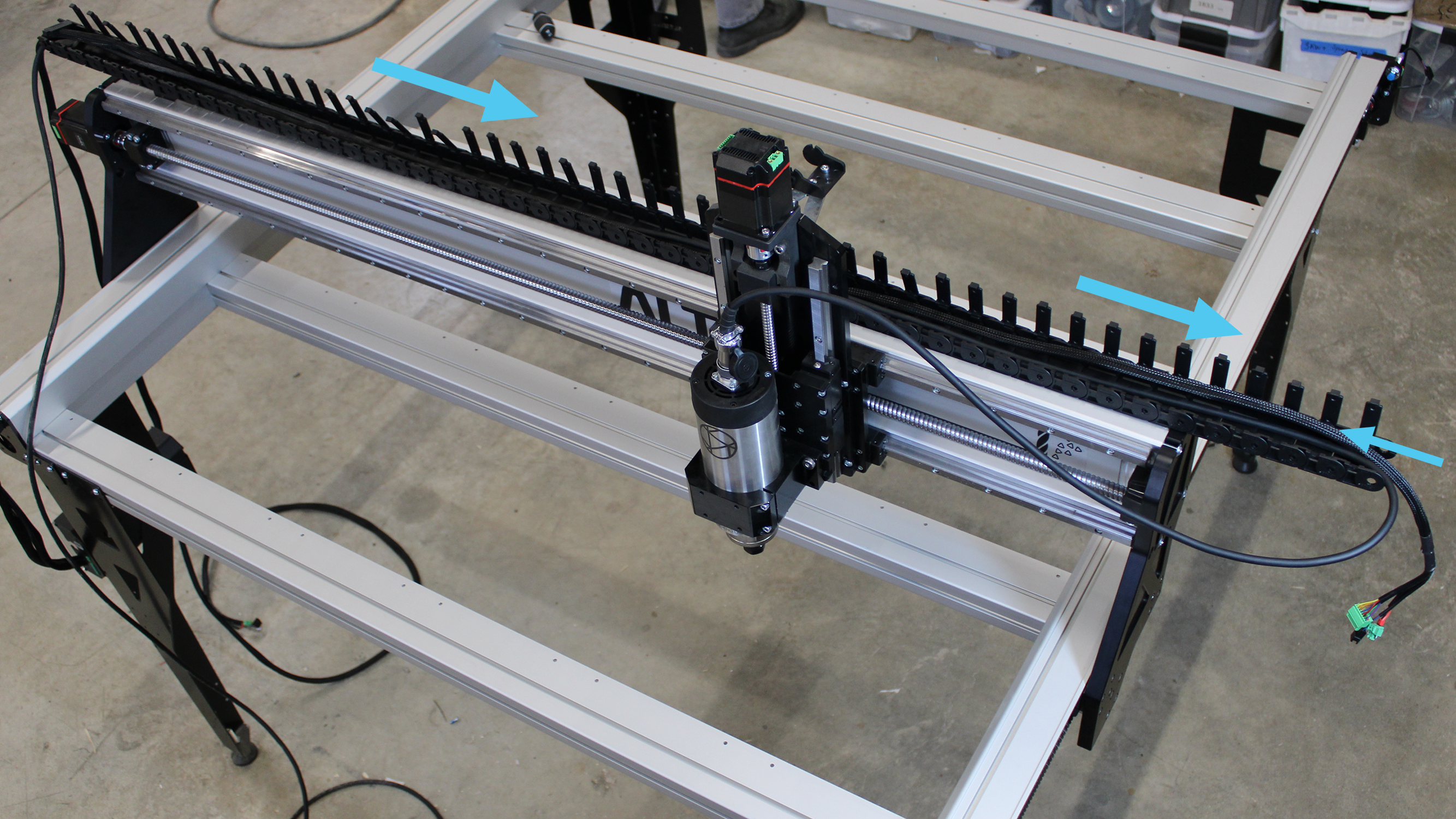
Routing through X-axis drag chain
To secure the cables, press some of the clips down. Install the drag chain onto the ends located at the drag chain bracket and on the X rail, beside the leftmost drag chain end. 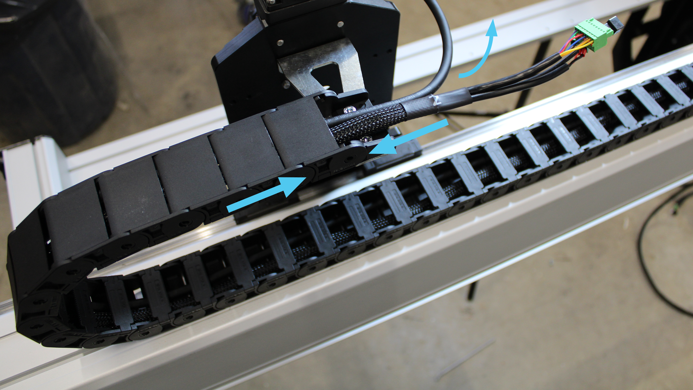
X-axis drag chain secured on Z-axis drag chain bracket
Place the other drag chain on the left Y rail. Run the X motor cable, as well as the remainder of the Z motor cable and spindle cable through it. The cables should enter towards the rear of the machine, and exit from the front. Leave the X cable ends sticking out.
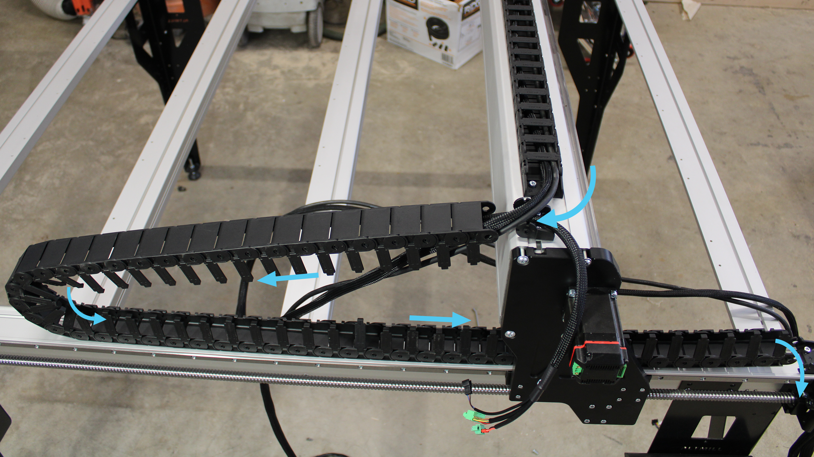
Routing through the left Y-axis drag chain
To secure the cables, press some of the clips down. Install the drag chain onto the ends located on the left Y rail, at the front of the machine, and on the X rail, at the leftmost of the machine. Finish clipping all drag chain clips to fully enclose the cables.
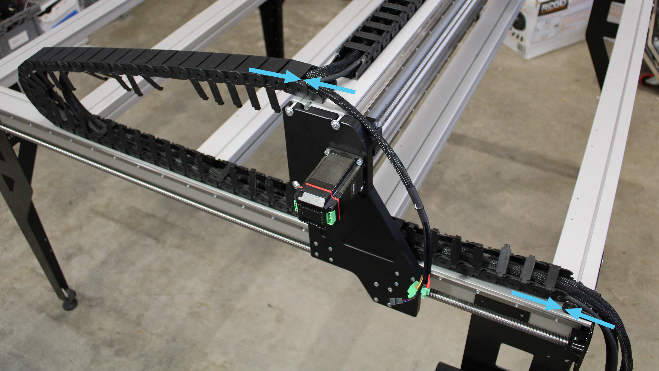
Securing left Y-axis drag chain on rails
Motor Connections
Connect the black connector exiting the X motor cable to the plug of the inductive sensor. Plug in the power and signal connectors from the X motor cable.
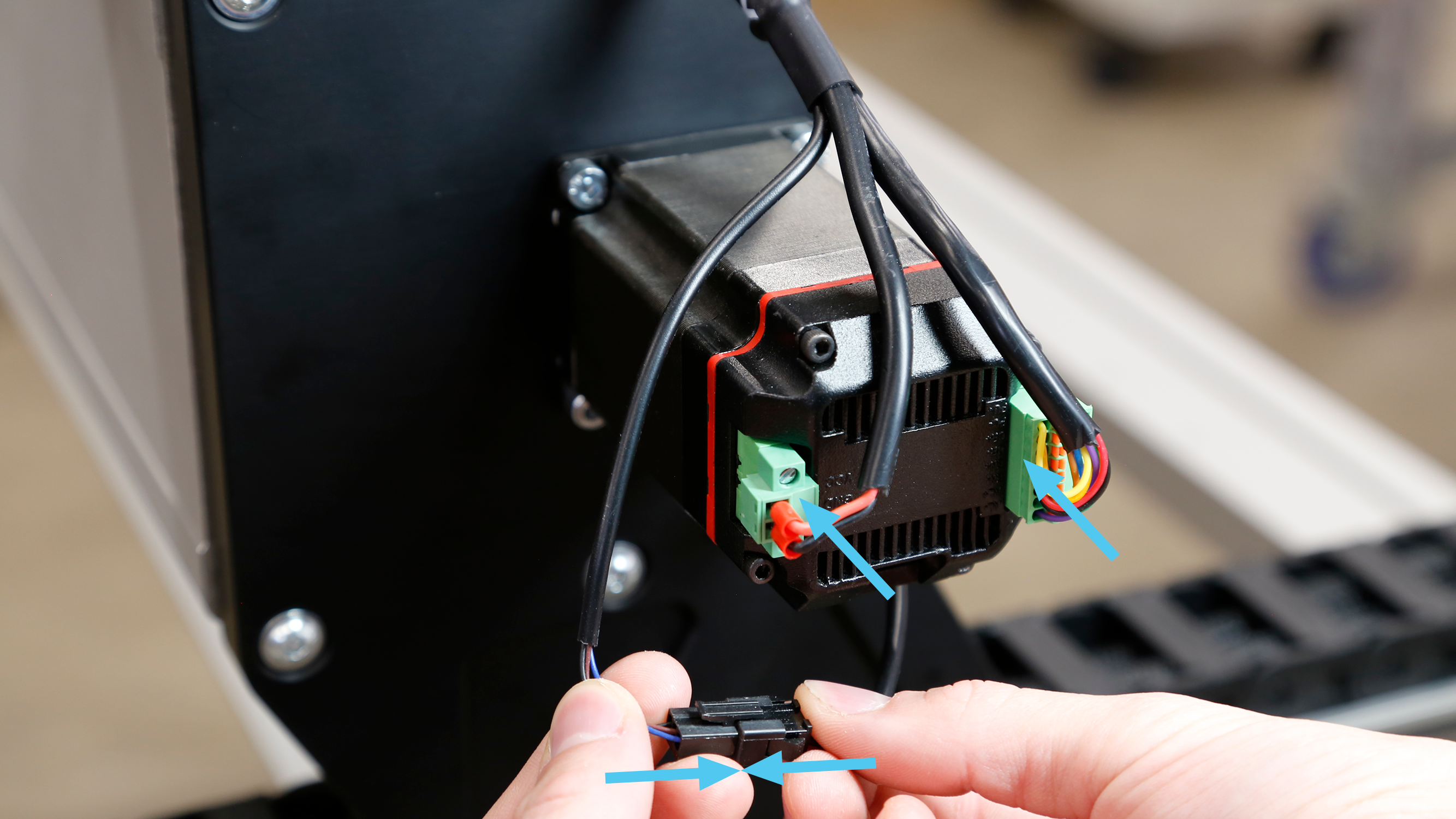
X-axis motor and signal connectors plugged in, sensor connector secured
Use a small flathead screwdriver to fasten the locking screws for the power connector.
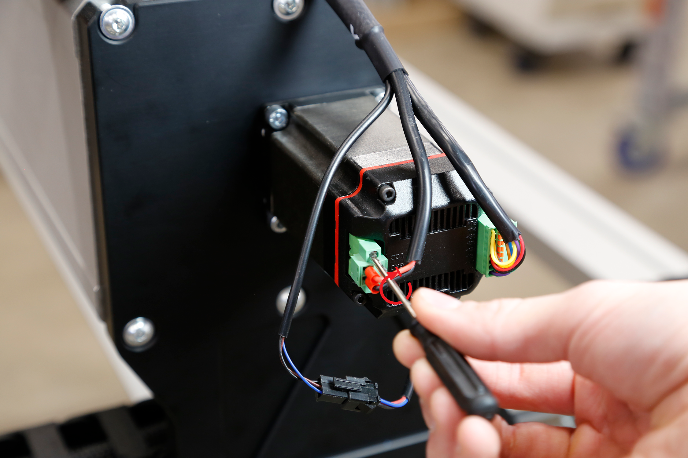
Tightly securing screws on power connector
Remove two of the M3 screws from the X-axis motor.
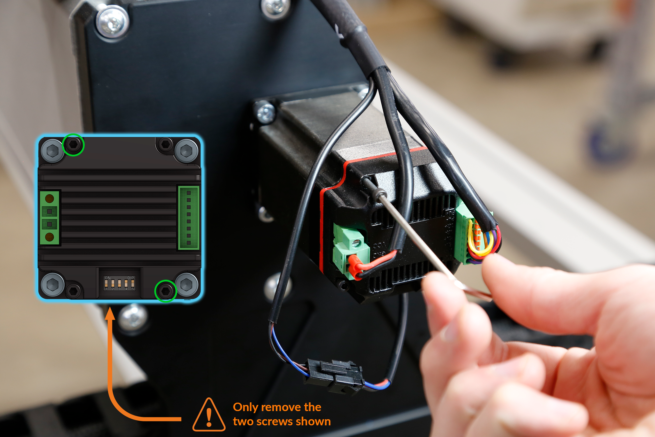
Removing 2 motor screws at a diagonal
Then install the motor cover using two (2) M3-40mm socket head screws, keeping in mind the correct orientation of the cover.
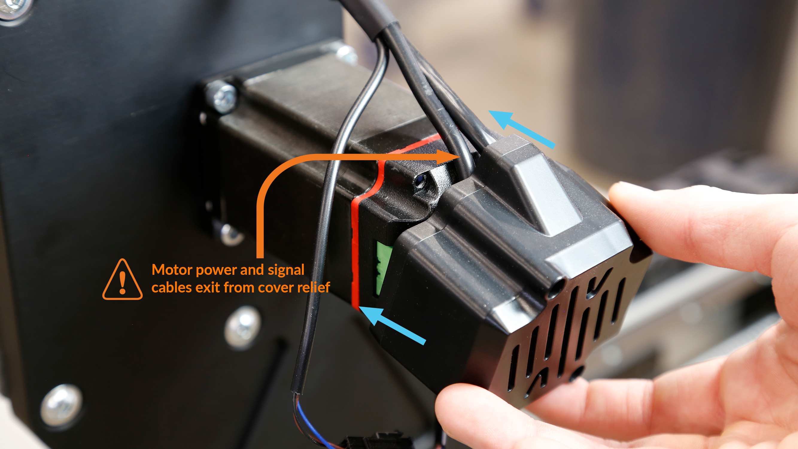
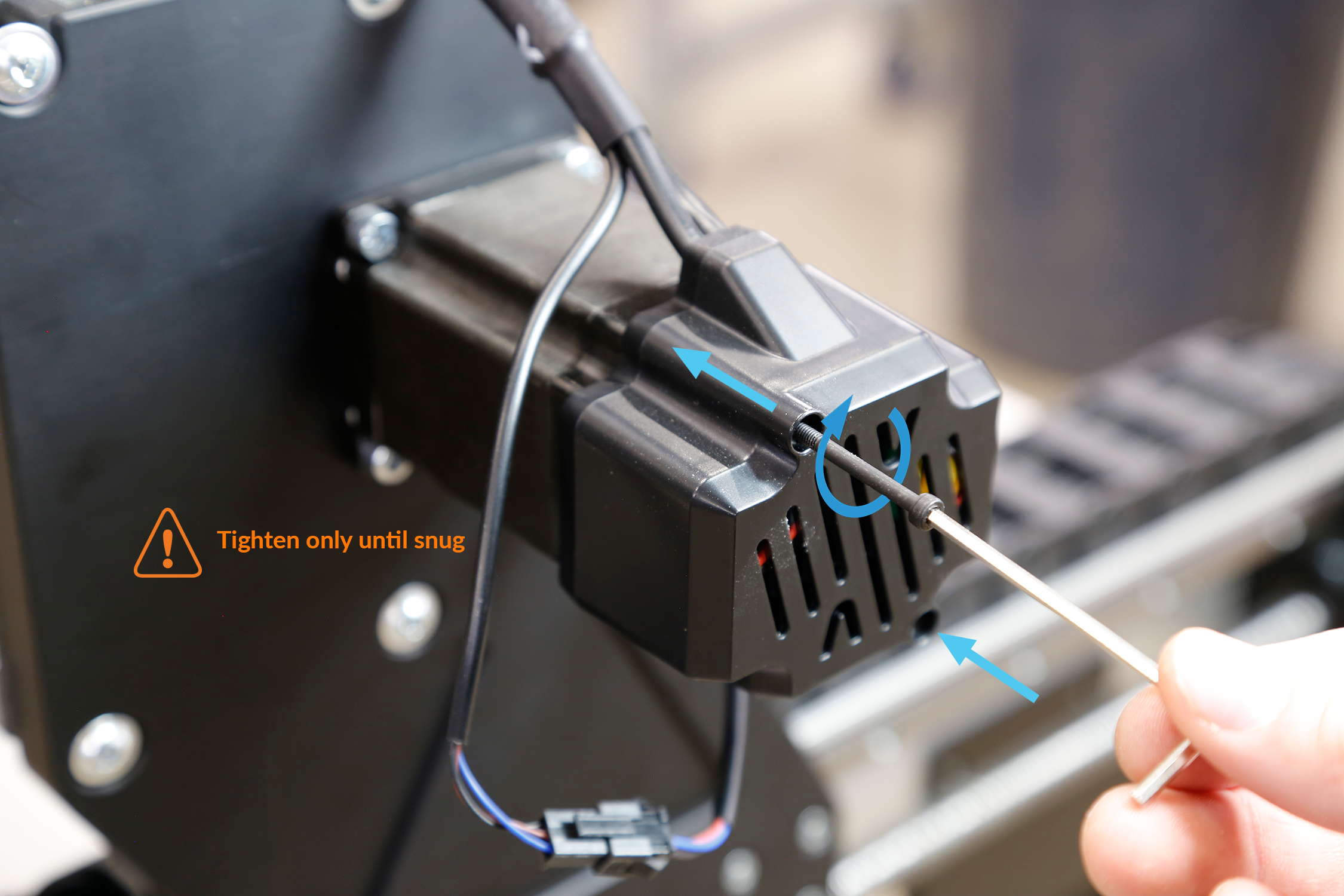
Motor cover installation
Repeat these steps for the Z, Y1 and Y2 motors. Note that the Y1 cable should be in the left Y-rail. Whereas Y2 cable should be spanning along the left Y-rail and rear crossbeam.
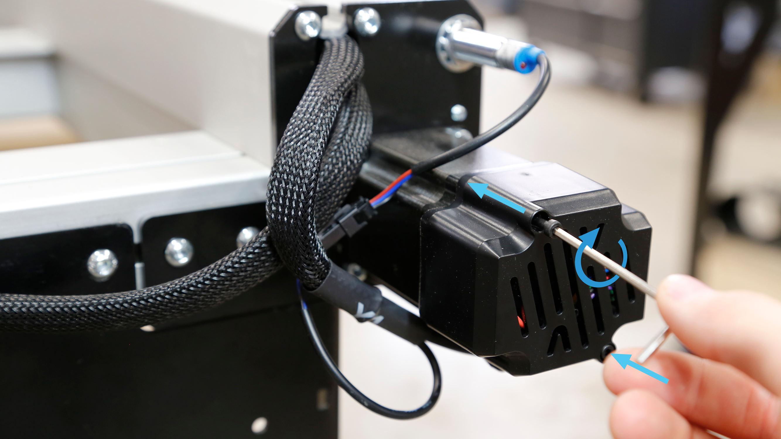
Assembling motor cover onto Y-axis
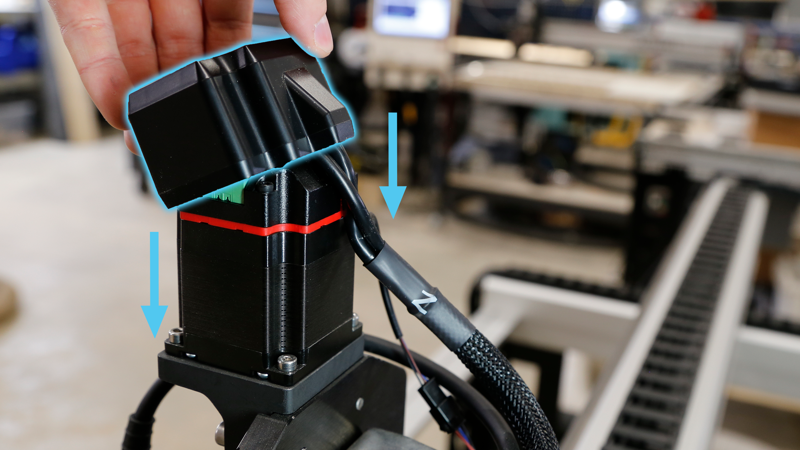
Assembling motor cover onto Z-axis
Once all motor connections are made and covers are assembled, secure zip ties onto the table legs as needed to manage cables.
