8. Controller and VFD
Parts Needed

Instructions
Electronics Mounting
1. On the front left table leg, on the same side as the drag chain carrier, insert two (2) M5-10mm SHCS and M5 washers from the inner face of the leg. From the outer face of the table leg, loosely fasten two (2) M5 T-nut on each screw.
2. Slide the SLB-EXT controller onto the T-nuts through the T-slot, then tighten the M5-10mm fasteners until secured.
3. Install two (2) M5 nylock nuts into the back of the VFD mounting spacer. Then use two (2) M5-40mm SHCS to fasten the E-stop to the VFD mounting spacer, clamping these two parts to the table leg. Ensure the clearance holes on the mounting spacer align with the holes on the leg.
4. Mount the VFD to the table leg using the threaded holes on the VFD, and two (2) M5-40mm SHCS. Do not force the fasteners into the VFD; slowly thread them in, or else you may push away the PEM nuts inside the VFD.
5. Remove the front cover of the controller to access the control board. Plug the motor connectors from the motor cables, paying special attention to the axis-specific sensor and signal ports. Plugging the cables into the wrong axis ports will cause issues!
6. Route the cables through the opening on the right side of the controller enclosure, then put the front cover back on.
7. Plug in the other end of the spindle cable into the bottom of the VFD, minding the keyed features. Turn the ring on the connector to fully secure the spindle cable.
8. Plug in the VFD power cable into the bottom of the VFD, and to the appropriate electrical outlet in your shop.
9. Plug the E-stop cable into the E-stop and controller.
10. Plug the RS14 (signal) cable into the RS485 port at the controller and bottom of the VFD.
11. Use two (2) sets of M4-8mm SHCS and M4 T-nuts to install the power supply onto the X-axis leg support at the front of the machine. Plug in the green power connector from the power supply to the controller.
gSender Settings
1. Turn ON the controller using the power switch.
2. If you haven’t yet, download gSender.
For detailed, step-by-step instructions on how to download and install gSender, go to this page.
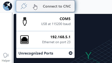
3. Check that the USB cable from the SLB-EXT controller to your computer is connected.
4. Then open gSender, and connect through the USB.
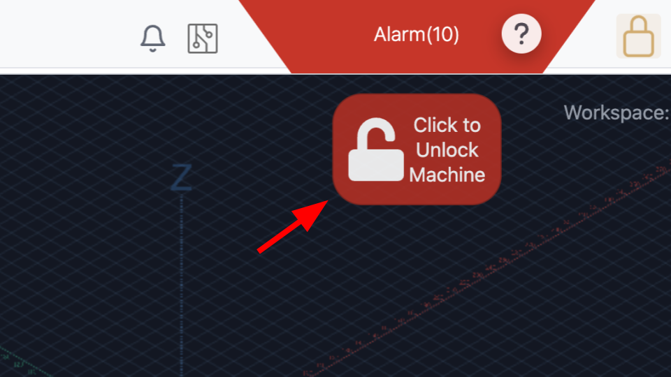
5. You will see a E-stop alarm. Clear the alarm by pressing and releasing the E-stop button, then press the red “Click to Unlock Machine” on the screen.
4. Go to Config, then at the bottom use the dropdown to select AltMill 4×8, then press the Defaults button. Press Restore Defaults, then turn OFF and ON your controller to have the changes take effect.