Machine Coordinates & Setting Zero
We’ll use gSender as our working example to explain key CNC control concepts that apply to most G-code senders. gSender provides a clear and visual way to understand how your CNC machine interprets coordinates, sets origins, and manages movement through different systems like machine coordinates, workpiece coordinates, workspaces, homing, and setting limits.
Download gSender or Read More about how it works!
Machine Coordinates vs Workpiece Coordinates
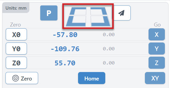
When you fire up gSender, and look to the right, above the Jog Controls is your DRO (Digital Read Out). This section allows you to do some automatic movement, set your zeros and see where you are in relation to the machine or the workpiece. Kinda like your car navigation system. You can also see if you are using mm or inches in the grey bar at the top/left.
Before we dive into the buttons in the DRO and what they do, let’s review how coordinates are handled. In other words, before we drive the car, let’s look at the map.
In CNC machining, there are two primary coordinate systems that guide the machine’s movements:
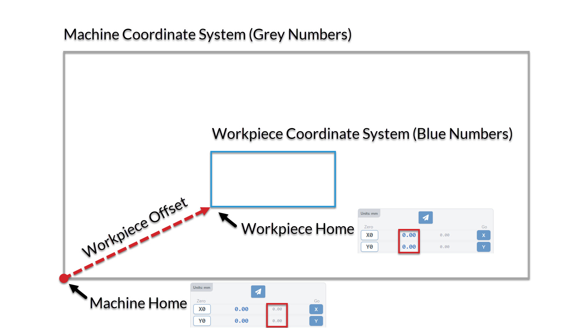
The machine coordinate system (MCS) is a fixed, default system established by the CNC machine’s manufacturer. It is defined by the machine’s physical size and is used during the homing cycle, when the machine references its internal limits using built-in sensors called limit switches. Users do not modify or choose this system—it simply tells the machine where it is in its own space. If you are not using limit switches, the machine home is determined by where the bit is when the controller is powered on.
In contrast, the workpiece coordinate system (WCS) is fully controlled by the CNC user. This system defines the position of the workpiece on the machine table and ensures the tool moves accurately in relation to the workpiece.
Machine Coordinate System 🏭
The machine coordinate system is a system defined by the machine’s physical size, telling us where the machine is at all times, relative to its travel limits. To do this, the machine must undergo an initialization process called the “homing cycle”, where it uses sensors placed at the end of each axis to automatically determine the travel limits. The user is not involved in this homing cycle. If the machine does not have sensors the machine cannot home, therefore the machine coordinate system can be ignored, and the machine home (0,0,0) will be arbitrarily set to wherever the machine is at the time the controller is powered on. In contrast, the wcs is fully defined by the user, in which the user sets where the system’s zero (0,0,0) is, relative to the workpiece. The machine will use this zero as the reference point for where to run the job, ensuring the tool carves accurately on the workpiece. All CNC machines, with or without sensors, require the user to set the zero.
When you power on the machine and perform a homing sequence, the machine references this built-in coordinate system to determine its position in space. This system ensures that the machine has a consistent reference point for all operations.
Workpiece Coordinate System 🧱
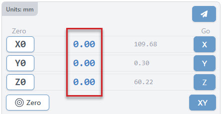
The workpiece offset is a user-defined coordinate system that aligns the machine’s operations with the specific location of the workpiece on the machine bed. This system allows users to set a new origin point (0,0,0) based on the workpiece’s position. This is indicated by the blue numbers in the DRO.
In gSender, you can set workpiece offsets using standard G-code commands, like G54 to G59. Workpiece offsets may utilize both homing and zeroing capabilities to enable you to have multiple workpiece coordinate systems, called “workspaces.” These are especially useful when working on different parts or setups without re-homing the machine each time.
Set Zero and Go tos
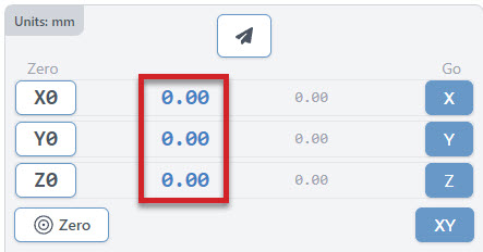
Each g-code file or project will have a starting position that all other movements are referenced off of. This is called the Workpiece zero. There are two ways to manually set your zero on gSender:
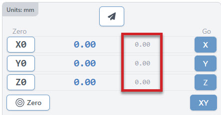
- Zero each axis one at a time using ‘X0’, ‘Y0’, and ‘Z0’ buttons
- Set them all at the same time with the larger Zero button
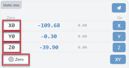
The large blue numbers tell you the current position of your machine. Once you set the zero of each axis, they will all read 0.00.
You can reset your zeros anytime when the machine is not actively running a job. The machine will remember your zero in most cases unless you forcibly move it by hand, but even then CNCs with homing can re-home and still return to the zero point.
Workspaces
Usually you would only have one origin or zero position for your project. However, if you plan to do a series of projects that require different zero positions, or are lining up to do some more complex jigging or part batches, you may want to set up multiple workspaces all at once. This can save you time by not having to set a zero position for repetitive tasks or specific jig setups. You can do this by creating up to six different zero positions with the six workspaces in gSender. Access each ‘Workspace’ at the top right of the program by pressing the drop down to select which workspace to use. gSender will act completely in-line with whatever workspace you’ve selected, whether you want to set zero, probe, surface, or anything else.
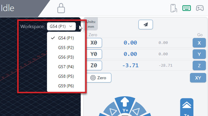
The use of different Workspaces is most helpful when the machine is able to home the machine coordinate system. Once homed you can select a workspace and setup your project, and gSender will remember where you set the zero for the new workspace. The challenge then becomes placing the project in the correct spot for each workspace. Often a jig is created, to ensure perfect placement for your workpiece each time. You can use a workspace without homing/limit switches, but it’s not very repeatable, and you would be resetting them often with each power cycle.
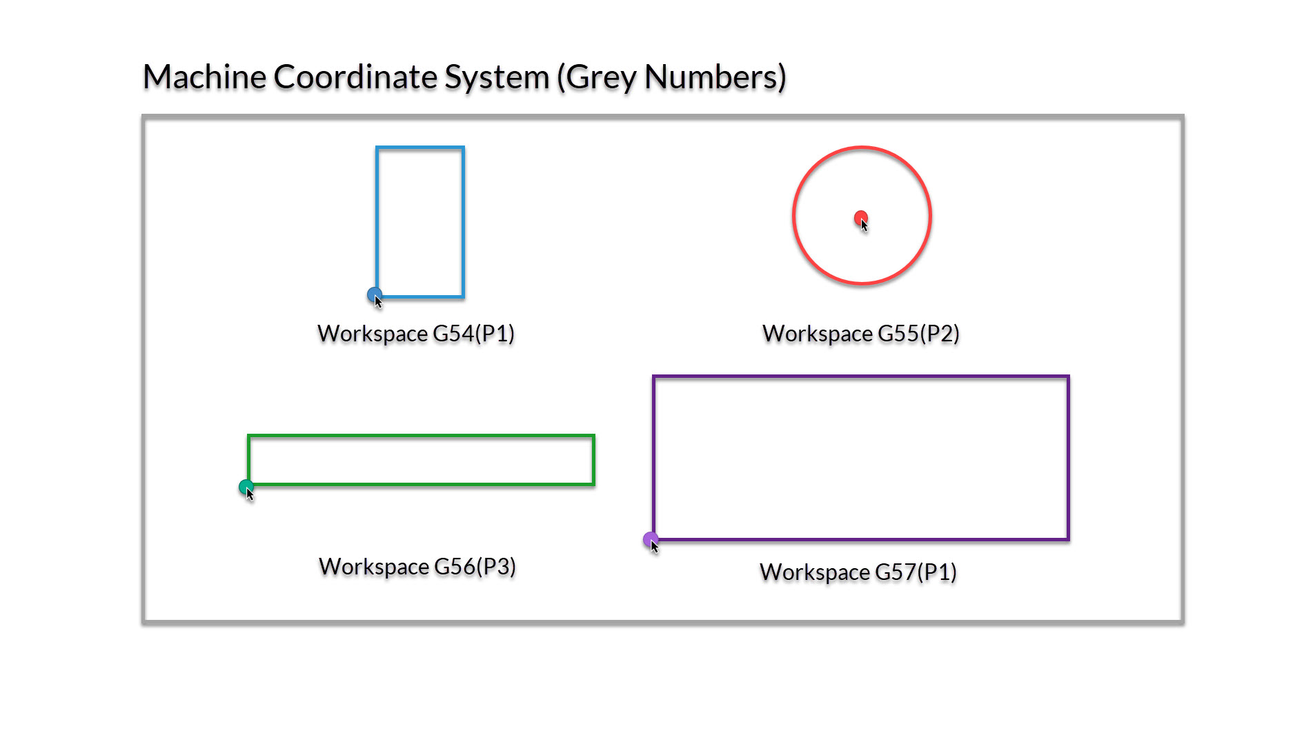
In the image below you can see 4 different workspaces setup, with the zero in the bottom left corner, and the circle in the middle.
Note: Some files may use a toolpath post processor that changes your workspace!
The video below explains the process in greater detail. If you’re coming from a more technical background, you’d usually call these ‘workspaces’ G54, G55, G56, … G59.
Homing & Limits
Limit switches (also referred to as inductive sensors, end stops or homing switches) are sensors that sit at one or both ends of each movement axis of a CNC to provide a few different functions. gSender provides unique features if you have these switches installed on your machine. You can check out our limit switches Sensor Kit
Homing
When we turn on homing, we can use 3 or more limit switches to find our machine coordinate home on our machine. For now, we will home to the front left corner of the machine. To enable Homing, Go to Config ➜ Homing/Limits ➜ Homing cycle enable ➜ toggle on.
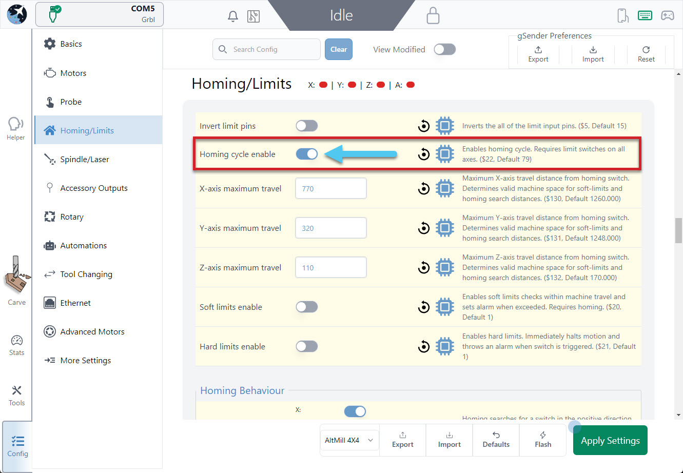
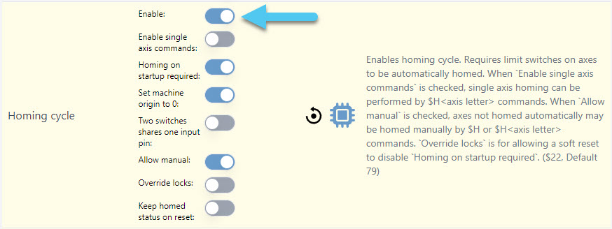
Using grblHAL enables several more detailed options for you to choose from, like homing single axes, requiring homing on startup, set machine origin to 0, and more. In this image, we have enabled homing, but not required it on startup. We have toggled to allow us to manually home the machine, and to Set the machine origin to 0 once complete.
You’ll notice additional buttons appear in the DRO area of gSender:
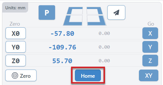
The Home button is a convenient way to home or re-home your machine at any time (sends the typical $h command). The machine will automatically move to your front left corner, using the limit switches to position the router over machine home.
Four Rapid-Travel buttons to move your CNC at its maximum speed to any of your machine’s 4 corners (offset by 5mm). These should only be used once your machine is homed.
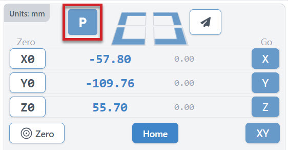
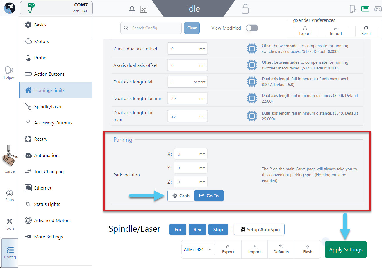
You can configure a Park Location to move your router to a set spot consistently at the click of a button. To setup your parking spot, Go to Config ➜ Homing/Limits and scroll down to the bottom of the section. Here you can enter the coordinates of your parking spot manually, or move your router/spindle to the spot you wish to park and hit the Grab current position button. Test out your new spot by hitting the Go to button in settings or hitting the P button on the DRO. Don’t forget to hit the Apply Settings button to save your new spot!
Setting Limits
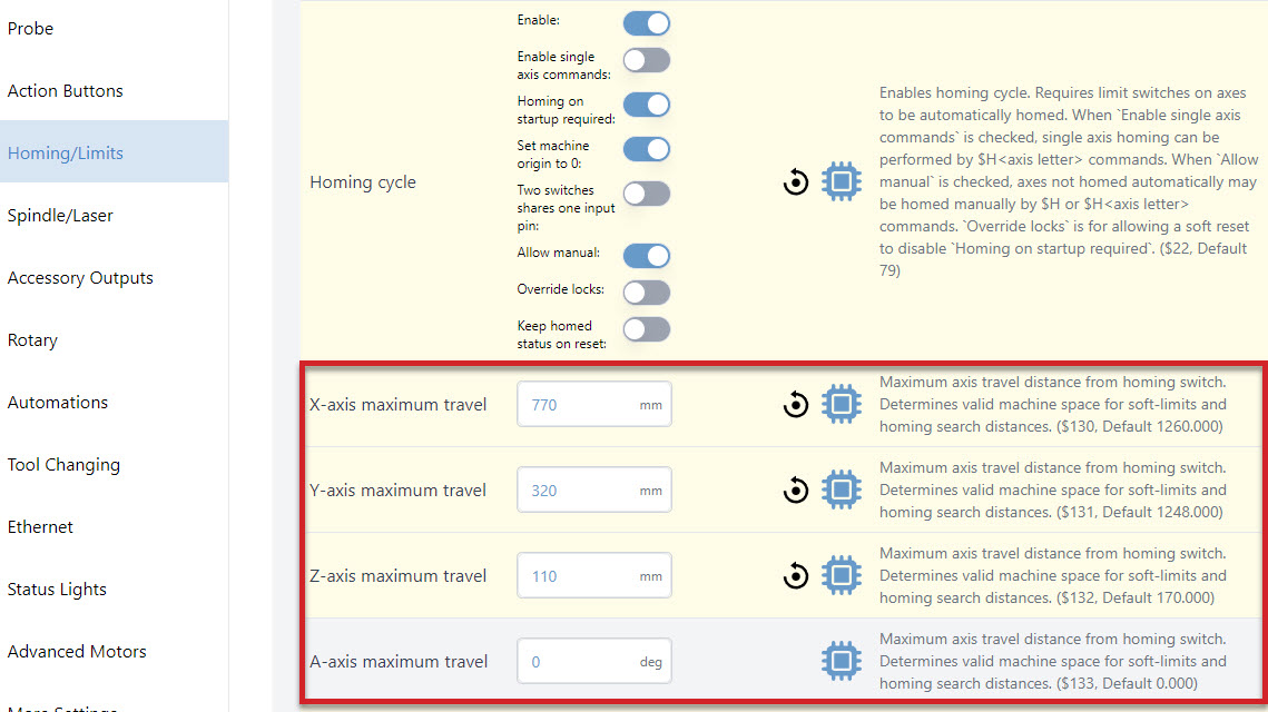
If you’re having issues with the “quick-travel” buttons, then check the maximum travel settings for your machine to see if they are the same as what your machine is physically capable of moving. You can find these settings by going to Config tab ➜ Homing/Limits ➜ X-axis maximum travel (Y, Z axes are here too), $130-$132. If you are using grblHAL you will also see A axis, $133.
If you’d like more information on how to set up and use limit switches, read here: https://resources.sienci.com/view/lm-adding-limit-switches/
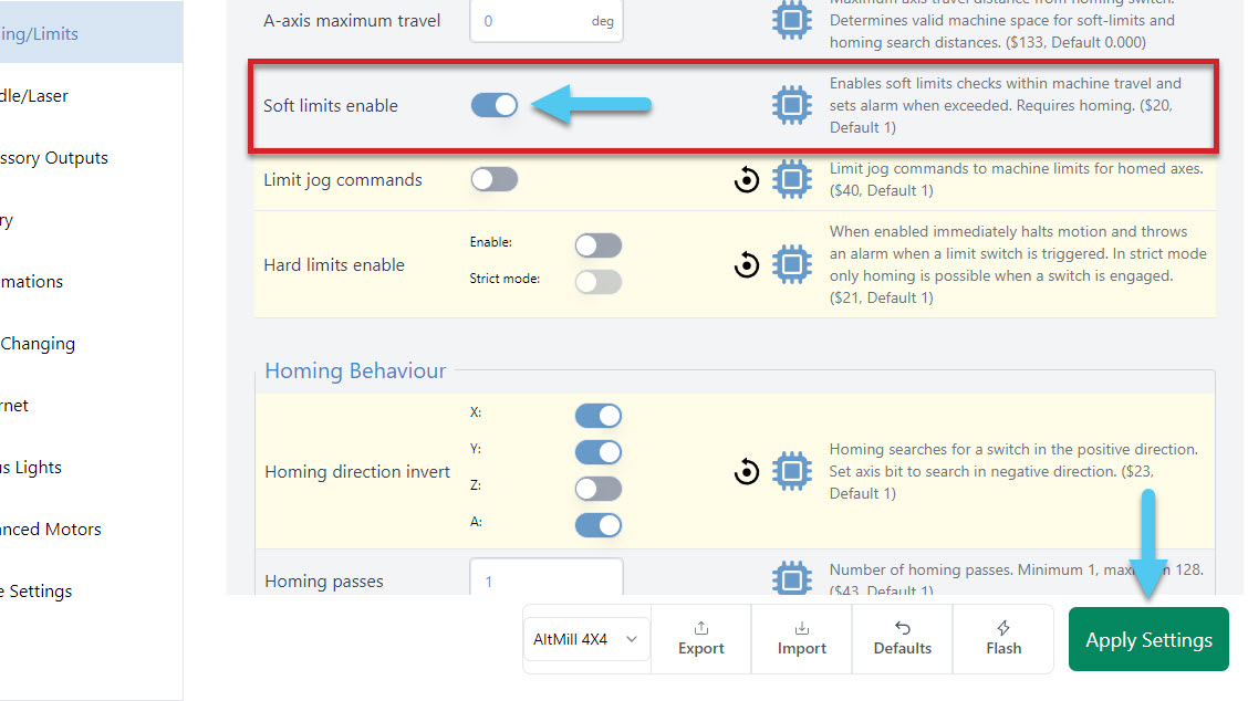
Soft Limits
With 3 limit switches in place, and homing turned on, we can turn on soft limits. This feature will combine your 3 limit switch homing cycle with your maximum travel lengths, to prevent you from going too far on each axis. Think of this as a software limit, we use 3 limit switches + your max travel to calculate your soft limits. To enable soft limits, Config ➜ Homing/Limits ➜ Soft limits enable ➜ toggle on. Don’t forget to hit the Apply Settings button to save!
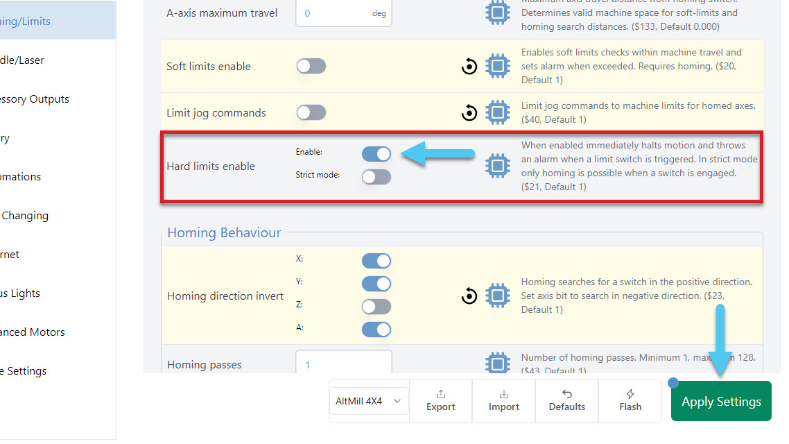
Hard Limits
With hard limits on, if your machine get’s close to the edge of an axis, your limit switch will trigger, stopping any further movement. To enable hard limits, Config ➜ Homing/Limits ➜ Hard limits enable ➜ toggle on. Don’t forget to hit the Apply Settings button to save!