Calibration Tools
Calibration Tools
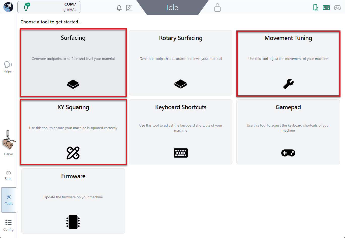
The Tool Tab is always available near the bottom left of the screen. Here you’ll find some tools that you can use to make finer adjustments to your machine for improved performance:
- XY Squaring
- Movement Tuning
- Surfacing
XY Squaring
When setting up any CNC, like when mounting a LongMill to a table, usually a squaring step is needed to ensure cuts don’t come out skewed. This Software Wizard (step by step guide) is a great asset to help speed things up by turning a typically ‘guess-and-check’ process into some easy measurements and behind-the-curtain math in 3 main steps:
- Mark 3 points on your machine to make a triangle (the larger the triangle, the better)
- Measure & enter the distance between the triangle points
- See the results and adjust accordingly
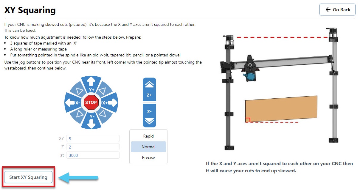
You will need the following:
- Ruler or measuring tape
- Tapered bit or V-bit
- 3 tape pieces marked with an ‘X’
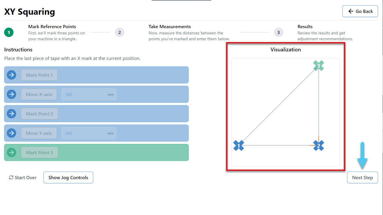
- Jog the machine to the front left corner, with the bit raised slightly over the surface of your wasteboard
- Mark the point with tape marked with an X, and move the machine as directed (Default 300mm)
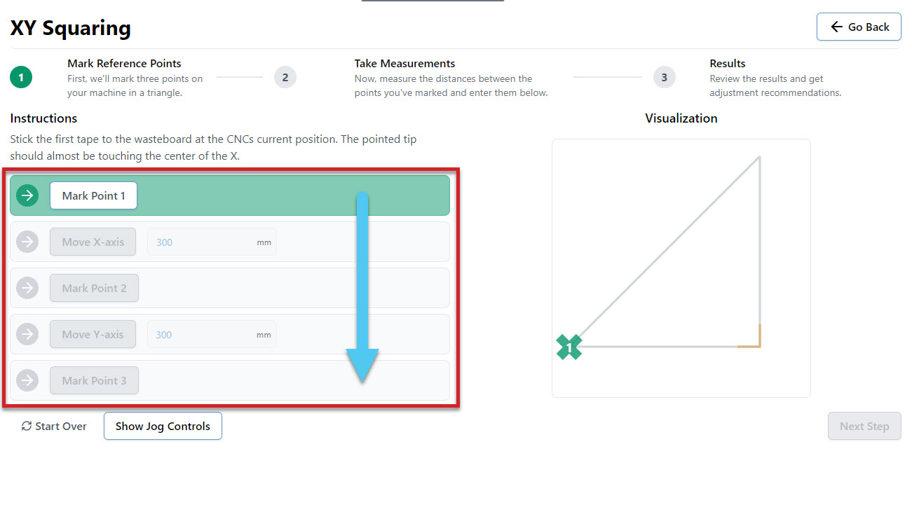
- Continue to mark points and move the machine until all boxes are complete and your triangle is marked
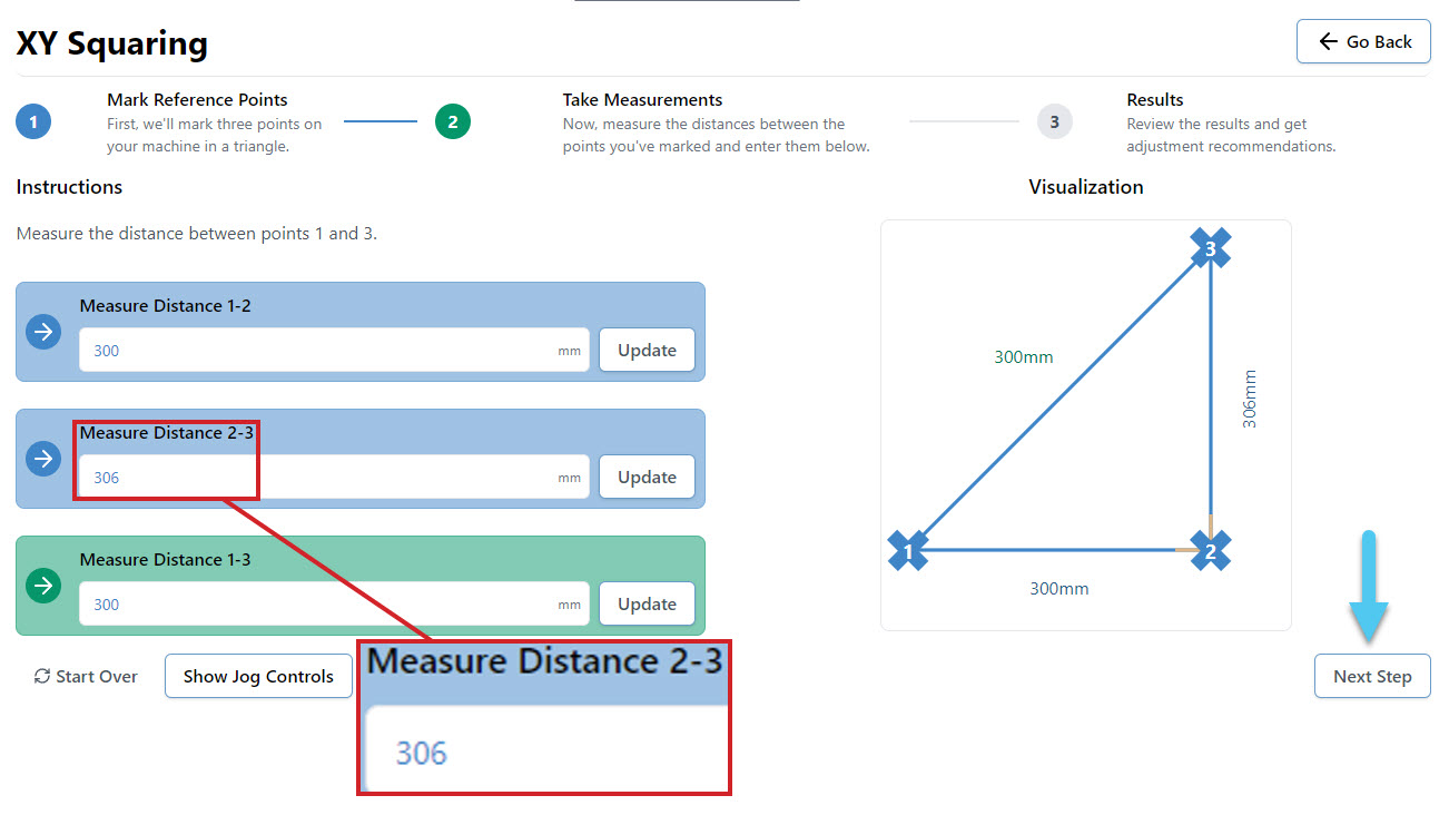
- Measure the distance between each X and enter the values into the 3 boxes. For instance you might measure 306mm, instead of the expected 300mm. Hit the Confirm button to move to the results page.
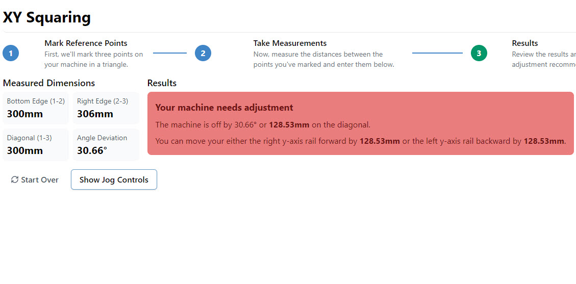
- At the end you’ll be told how square your machine is and whether you need to take action to adjust it further or if it’s close enough that you can leave it. The squaring tool also keeps an eye out for if your steps/mm (axis travel resolution) are off and can adjust those too.
You can also try watching how this process works in this user-made video by SparksTech!
Movement Tuning
Another Software Wizard (step by step guide) found in the Tool tab. This one is designed to help fine tune how much your motors turn to improve the accuracy of your machine movements. This is done through modifying the EEPROM settings stored on your CNC. You can tune the X, Y and Z axes individually.
You will need:
- Marker or tape
- Measuring tape
- Jog your machine to the middle of whichever axes you choose to tune, so that there is enough room to complete this procedure. For example, on the X-axis you would jog halfway on the X-axis rail
- Select what axis to tune on the drop down menu
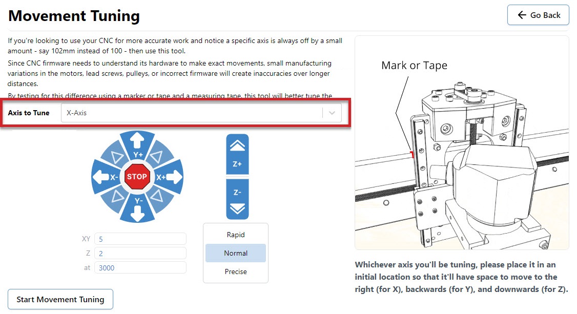
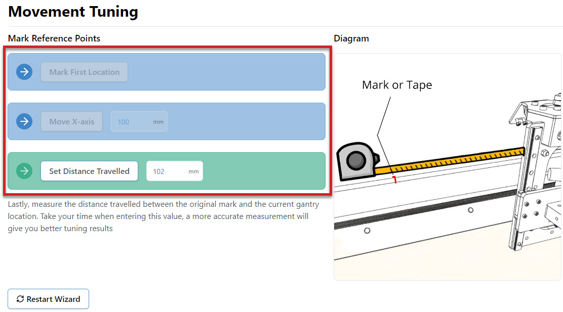
- Mark down the starting location as a reference point on the machine. For example the X-axis tuning references the edge of the XZ gantry on the X rail.
- Move the axis a chosen distance (Default 100mm)
- Measure the distance between the starting location and the finishing location
- Enter the measured value into the Set Distance Travelled box
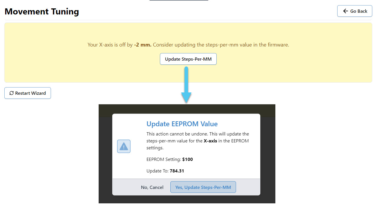
- You can now change the EEPROM setting if recommended by the procedure by pressing Update Steps-per-MM. This will bring up a popup that explains the change about to be made, and allows you one last chance to cancel the update.
- Repeat the procedure for each axis you wish to tune
Surfacing
Surfacing the wasteboard of your machine or any project or blank material, can easily be done right inside gSender from the Tools tab! This saves the hassle of drawing rectangles in your CAD/CAM program and moving files around until you get the settings right. It’s also great for creating a perfectly flat surface of your starting materials, just like a jointer or surface planer would. You can also use the Rotary Surfacing Tool if you are wanting round stock off a rotary axis.
If you plan to use this tool to surface your wasteboard or larger pieces of material, some extra advice we’d give is to remove any accessories that might get in the way of your machine travelling to its limits as well as have a good vacuum on hand because surfacing can get really messy.
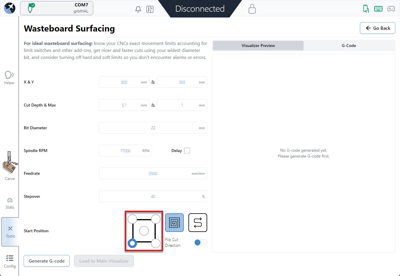
- Start by entering the settings you’d like to use to generate your surfacing job on the left side:
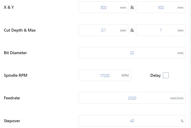
- X & Y: decides the cutting size (width and depth) you want to surface. If you’re surfacing your wasteboard, use the manufacturer’s spec on max machine travel or manually jog to the limits to cover the full cutting area, or if you’re surfacing a piece of material then you can use a measuring tape.
– AltMill: 1265mm (49″) x 635mm (25″) or 1251 (49″)
– LongMill MK2: 818mm (32.2”) or 1278 (50.3”) x 366mm (14.4”) or 866 (34.1”)
(if using limit switches, remove about 8mm/0.3” in X and 11mm/0.43” in Y)
– LongMill MK1: 320mm (12.6”) or 805 (31.7”) x 344mm (13.54”) or 844 (33.23”)
(if using limit switches, remove about 35mm/1.38” in X and 24mm/0.94” in Y)
(if using magnetic dust shoe, remove about 34mm/1.34” in X)
– Mill One: 235mm (9.25”) or 257 (10.1”) x 185mm (7.28”) - Cut Depth & Max: describes how deep you want to cut per pass and the total depth you want to cut down. For larger surfacing bits usually you should keep cut depth below 1mm, max depth should be increased to a couple millimeters if you think your material is very warped.
- Bit Diameter (typically 6 – 25mm): make sure you have the right bit for the job like a surfacing tool or a large, flat end mill since this will give you a better surface finish.
- Spindle RPM (default 17000): only applies if you have an automatic speed control, otherwise set this manually on your router.
- Feed rate (default 2500mm/min): influenced by the RPM, step over, bit diameter, and cut depth. Luckily if you set it incorrectly you’ll be able to override it during the job since surfacing can cause burning when cutting too slow or can have worse surface finish when cutting too fast.
- Stepover (default 40%): sticking around 40% tends to be a good balance between speed (using a higher %) and better surface finish (using a lower %).
- X & Y: decides the cutting size (width and depth) you want to surface. If you’re surfacing your wasteboard, use the manufacturer’s spec on max machine travel or manually jog to the limits to cover the full cutting area, or if you’re surfacing a piece of material then you can use a measuring tape.
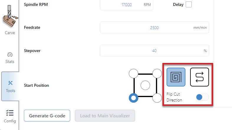
- Decide where you want to start surfacing from by clicking any of the corners or the center. In most cases the front, left of the machine is the most convenient, and is the default setting. You can also select a surfacing pattern of spiral or zig-zag. The spiral will only cut from the inside-out if the start position is the centre. If you toggle the flip cut direction, the spiral will cut conventional instead of climb, and the zig-zag pattern will cut vertically instead of horizontally.
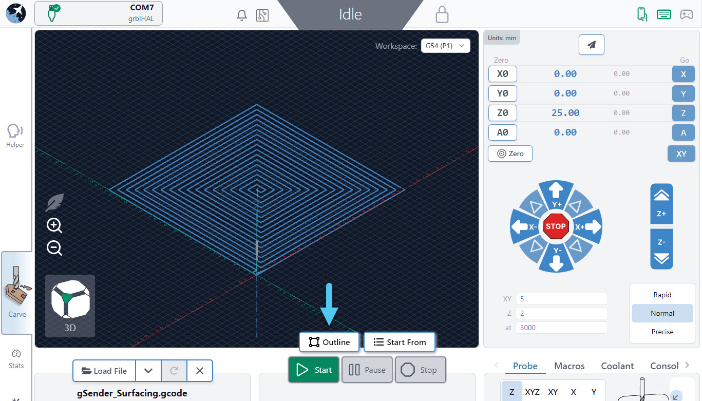
- Press ‘Generate G-code‘ and check your surfacing tool path using the ‘Visualizer Preview’ tab. You can also see the raw g-code using the ‘G-code Viewer’ tab and can copy and save it to a g-code file if you’d like to use it again later.
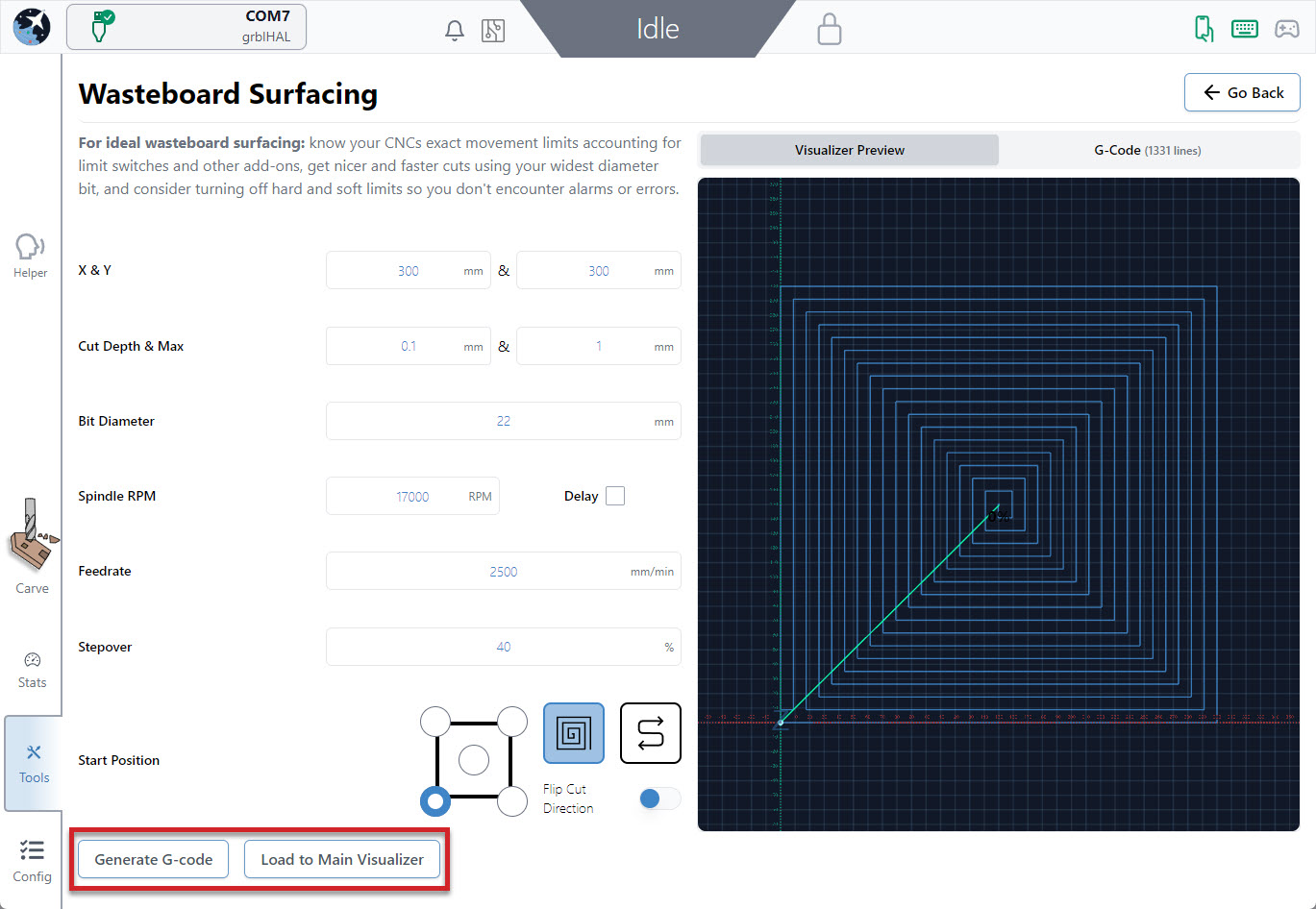
- Press ‘Load to Main Visualizer‘ to bring the g-code into gSender’s main screen. Make sure that you jog to the starting point and set your zero in the right place before starting the job. You can also press the ‘Outline‘ button as an easy way to check that you’ll be surfacing where you expect and if you find the dimensions aren’t correct you can always re-open the surfacing tool, tweak the size, and try again. Feel free to start the job whenever you’re ready!