LongBoard Details
The LongBoard is a powerful, three-axis CNC controller and driver system for the LongMill and other CNC routers. LongBoards run with grbl firmware and come with four TB6600 driver modules that run single X and Z-axis, and dual Y-axis bipolar stepper motors making them suitable for small to medium size hobby CNC routers. They also come with an assortment of inputs and outputs that allow users to connect items such as limit switches, probes, spindle control, coolant control, lasers, and more.
The LongBoard was jointly designed by our friend Chris Hadjuk and the rest of the Sienci Labs team.
Technical specs
Electrical
Input voltage
The LongBoard has an operating voltage range of 12V to 48V. Most LongMills come standard with a 24V power supply.
The input voltage to the drivers can impact the performance of your machine. For more info, check out these articles:
- Elinco International JPC – Stepper Motor Voltage Explained
- MachineDesign – Misconceptions about Stepper Motors Explained
- SGS-Thomson Microelectronics – Stepper Motor Driving
The LongBoard also comes with an Arduino UNO as the “brains” of the controller. The Arduino UNO requires a 5V input from the computer to operate correctly. In some instances, the UNO can operate at a voltage of 3.3V but some of the output voltages (such as for the limit switches or spindle control) may not work correctly.
Input current
The LongBoard can draw up to 16A. However, by default, they are set to draw up to 8.8A. You can directly adjust the minimum and maximum current draw of each driver using the potentiometer found on each driver. More info can be found here: https://resources.sienci.com/view/lmk2-stepper-driver-current/
The Arduino UNO can draw up to 500mA from your computer USB port.
Driver specs
The LongBoard uses four TB6600 drivers. The data-sheet for the driver chip can be found here: https://toshiba.semicon-storage.com/us/semiconductor/product/motor-driver-ics/stepping-motor-driver-ics/detail.TB6600HG.html
Specification for the driver may vary due to the operating limits of periphery components:
- Type: Bipolar stepper motor driver
- Microstepping: Full, Half, Quarter, 1/8, 1/16 step resolution / Pseudo-sinewave drive (PWM chopper type) / High output current / Low R-on / Power-on reset circuit
- Max output current: 4A
- Max output voltage: 48V
- Operating temperature: -30C to 85C
Mechanical
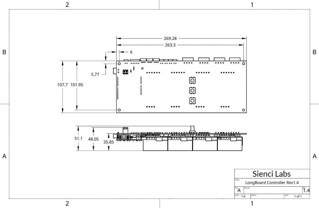
Dimensions
For 3D models of the LongBoard, please visit our open source documentation page for access to files if you wish to acquire additional dimensioning: https://resources.sienci.com/view/lmk2-open-source/
Connectors
The LongBoard comes with many inputs and outputs which users can implement easily using the detachable screw terminals or connectors that come on the board. More info on how each input and output works can be found below in the documentation.
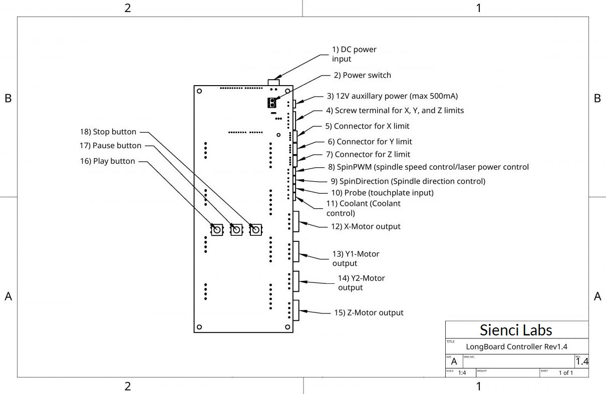
Below are the connectors used with links (male):
- Connector 1, 2: WJ2EDGK-5.08-2P
- Connector 3, 8, 9, 10, 11: WJ15EDGK-3.81-2P
- Connector 4: WJ15EDGK-3.81-5P
- Connector 5, 6, 7: XHP-4
- Connector 12, 13, 14, 15: DB2EK-5.08-4P
- Connector 12, 13, 14, 15 (Motor side, not board side) JST XHP-11 or TE Connectivity 1586019-4
Firmware
Introduction to grbl
The LongBoard’s Arduino UNO comes pre-installed with grbl firmware. Users can modify settings using EEPROM settings or flash entirely new firmware onto their boards if they wish.
From the grbl website:
Grbl is a no-compromise, high performance, low cost alternative to parallel-port-based motion control for CNC milling. This version of Grbl runs on an Arduino with a 328p processor (Uno, Duemilanove, Nano, Micro, etc).
The controller is written in highly optimized C utilizing every clever feature of the AVR-chips to achieve precise timing and asynchronous operation. It is able to maintain up to 30kHz of stable, jitter free control pulses.
It accepts standards-compliant g-code and has been tested with the output of several CAM tools with no problems. Arcs, circles and helical motion are fully supported, as well as, all other primary g-code commands. Macro functions, variables, and most canned cycles are not supported, but we think GUIs can do a much better job at translating them into straight g-code anyhow.
Grbl includes full acceleration management with look ahead. That means the controller will look up to 16 motions into the future and plan its velocities ahead to deliver smooth acceleration and jerk-free cornering.
- Licensing: Grbl is free software, released under the GPLv3 license.
- For more information and help, check out our Wiki pages! If you find that the information is out-dated, please to help us keep it updated by editing it or notifying our community! Thanks!
- Lead Developer: Sungeun “Sonny” Jeon, Ph.D. (USA) aka @chamnit
- Built on the wonderful Grbl v0.6 (2011) firmware written by Simen Svale Skogsrud (Norway).
There is a wealth of information and knowledge available on the grbl Wiki pages that can help you use the LongBoard or customize features and functions of your machine. We recommend reading through the Wiki pages if you are looking to explore additional modifications to your LongBoard through the firmware or if you need help with setting up new machines.
grbl Configuration
grbl Firmware
Download links to LongMill MK2 firmware can be found here: https://resources.sienci.com/view/lmk2-grbl-firmware/
For information about flashing your Arduino with new firmware, please visit the link above or visit the instructions provided in the grbl Wiki: https://github.com/gnea/grbl/wiki/Flashing-Grbl-to-an-Arduino
Default LongMill MK2 grbl EEPROM settings
The LongBoard comes with EEPROM settings set to work best with the LongMill MK2. For information about what each setting is and what it does, please visit: https://github.com/gnea/grbl/wiki/Grbl-v1.1-Configuration
You may need to change EEPROM settings if you wish to add additional functionality, such as limit switches or spindle control.
Each setting can be changed to suit the user and their machine. We recommend that LongMill MK2 users keep the same default settings for their machines, and check their settings if they are having issues.
To see the list of LongMill MK2 default EEPROM settings and for more EEPROM info, please visit: https://resources.sienci.com/view/lmk2-eeprom-settings/
Inputs and outputs
Power and switch
The LongBoard comes with a detachable emergency stop button that can be plugged into the controller to kill power to the controller in the case of emergency or just to turn the machine off.
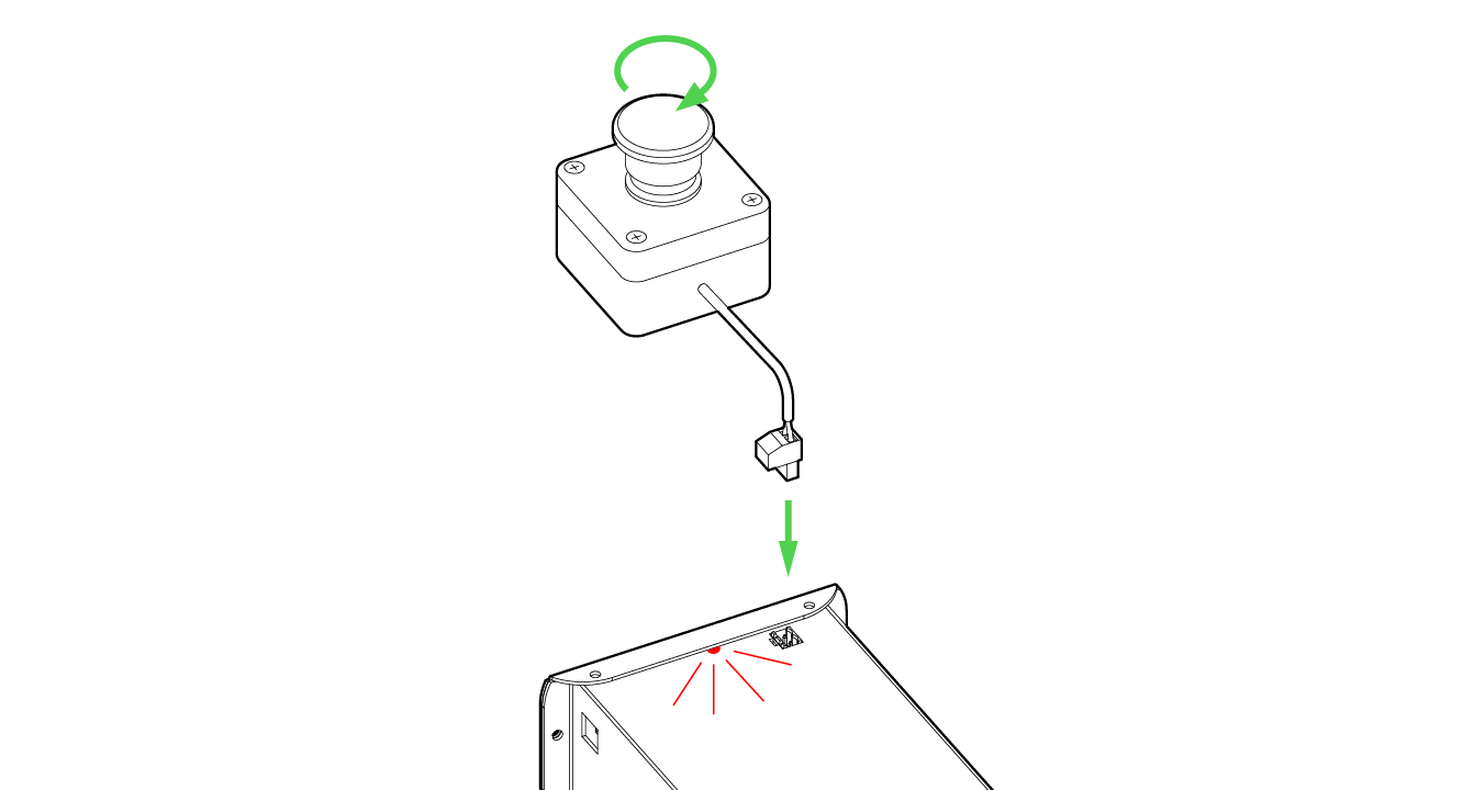
E-stops come with around 2-3 feet of cable preinstalled. Users can extend this wire if they wish. If you wish to use a longer cable, you must use at least 16AWG gauge wire. We recommend keeping the cable under 6ft long since the longer the cable is, the more power loss you may experience.
The LongBoard must have a switch installed for it to operate. The controller will not be able to provide power if the switch is not installed.
12V auxiliary power
The LongBoard provides auxiliary power for adding fans, lights, and other low current add-ons. We recommend limiting the current draw from this plug to 500mA as drawing too high of a current may limit current to the drivers.
Play, Pause, and Stop Buttons
The LongBoard comes with three buttons on the top of the controller that can be used to control the machine during its operation. Pressing these buttons will trigger the control software such as UGSPlatform to perform an action.
These buttons may be useful for some users as it allows you to play, pause, or stop a running job without touching the computer.
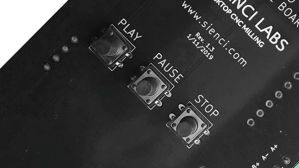
Play:
NOTE The machine must be paused in the middle of a job for the play button to work. The play button can be used to resume a job that has been paused.
Pause:
The pause button will pause a running job. Pressing the play button will resume the job.
Stop:
The stop button will stop a running job. Once you press the stop button, you will not be able to continue a job. When you press the stop button it will also throw an alarm and you will have to reset your connection with UGS or perform a “soft reset”.
Limit switches
For info about adding limit switches please visit: https://resources.sienci.com/view/lmk2-limit-switches/
Spindle/Laser control
You can control spindles and lasers using the SpinPWM and SpinDirection outputs on your LongBoard.
SpinPWM:
SpinPWM allows users to send a M3 SXXX or M4 SXXX command to control the spindle speed. It is important that you have the correct minimum and maximum spindle speeds on your EEPROM settings as the PWM signal outputted by the controller will be linearly related to the spindle speed scale.
For example, if your minimum spindle speed is 0 and your maximum spindle speed is 30,000, then the command “M3 S15000” will signal the PWM to be on half of the time, or if you measure with a voltmeter, should read 2.5V.
As a side note, M5 sets the SpindlePWM signal to LOW.
You can also use SpinPWM to control a laser. For additional documentation for lasers, please visit: https://resources.sienci.com/view/lmk2-adding-a-laser/
Spin Direction:
The M3 command turns the Spin Direction output to HIGH, indicating that the spindle should rotate clockwise.
The M4 command turns the Spin Direction output to LOW, indicating that the spindle should rotate counterclockwise.
Oftentimes, you may not have the option to control the direction of your spindle, or it will default to clockwise if you do not have Spin Direction connected. In most instances, most users will not need to control the spindle direction and can leave this output alone.
Probe
The probe input allows the use of a touch plate or probe with the LongBoard.
For documentation on setting this up, please visit: https://resources.sienci.com/view/lmk2-touch-plate/
Coolant control
Coolant works similar to spindle control. Sending an M7 command sets the coolant pin to HIGH and sending an M9 command sets it to LOW.
Adapting to a Given CNC
With the inputs and outputs available on the LongBoard controller, it’s easy to adapt it to to any given CNC system with:
- up to four, 4-wire stepper motors
- up to three pairs of 2-wire limit switches
- one 2-wire probe
- one spindle, wired to a VFD that can accept a 0V or 5V direction signal and a 0-5V PWM signal
- and remaining periphery for one, constant 12V and one, switchable 5V signal
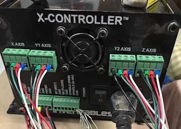
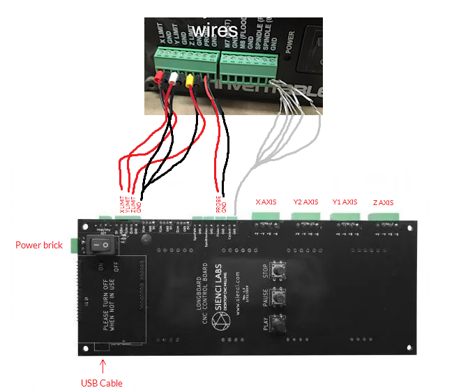
We’ll use an X-Carve as an example. Out the back of the X-Controller™, you can see stepper motor inputs labelled as “X AXIS”, “Y1 AXIS”, “Y2 AXIS”, and “Z AXIS”. These are already bundled into 4-wire terminal connectors, the same kind that the LongBoard uses, so by unplugging them from the X-Controller™ and plugging them into the similarly labelled sockets on the LongBoard you’ve already got the motors transferred over.
The other common inputs (the limit switches and probe), are also easy to bring over due to labelling similarities. The X-Controller™ and the LongBoard also both have terminal block connectors where wires can be easily attached and detached from the connector via the slotted head cutouts in the connector using a small, flat headed screwdriver.
With the wiring complete, the last step is to configure the EEPROM of the LongBoard. The LongBoard should already come pre-flashed to accommodate most machines, but it won’t know if the motor is turning the wrong way, what the size of the machine is, or if you have a spindle or limit switches. This step is to give the controller an understand of what your CNC looks like so the controller can know how to move it around correctly. Many CNC manufacturers will provide these settings to their customers for proper configuration. Some examples are (though understand that machine settings can change all the time so these values might be out of date):
- Shapeoko: https://www.reddit.com/r/shapeoko/wiki/grbl/
- X-Carve: https://discuss.inventables.com/t/x-carve-grbl-default-settings-500mm/13824
The values that you’ll be most interested in for initial setup will be:
- $2 and $3 to get your motors moving in the correct direction
- $100, $101, and $102 to get your motors moving the correct distances
- $5 and $22 to $27 to accommodate your limit switch type, enable homing, and set other homing settings
- $20 and $21 for other options based on how you want to be using your limit switches
Otherwise, some of the more optional values would be:
- $30 and $31 for configuring spindle speed range
- $110 to $132 for configuring the machine boundaries, maximum velocity, and maximum acceleration
Once you’ve determined that these values reflect the current mechanics of your machine, you should be ready to go!
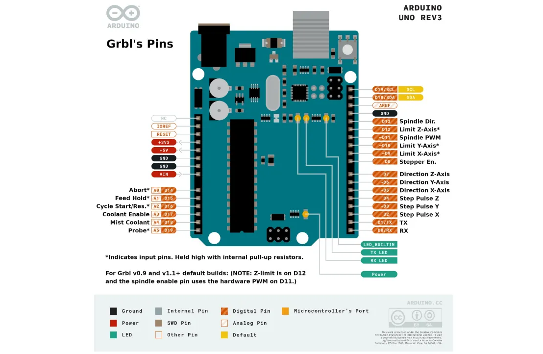
Arduino Routing
Fundamentally most of the work the LongBoard does is reroute the Arduino Uno’s IO to convenient connectors for easier machine setup, with some added circuitry to reduce EMI, plus motor drivers and onboard buttons. The routing of the IO is the same as what’s shown below (image credit to https://lo.manuals.plus/cndy-shield/grbl-cnc-arduino-uno-manual)