4. Drag Chains and Cables
Drag Chains and Cables
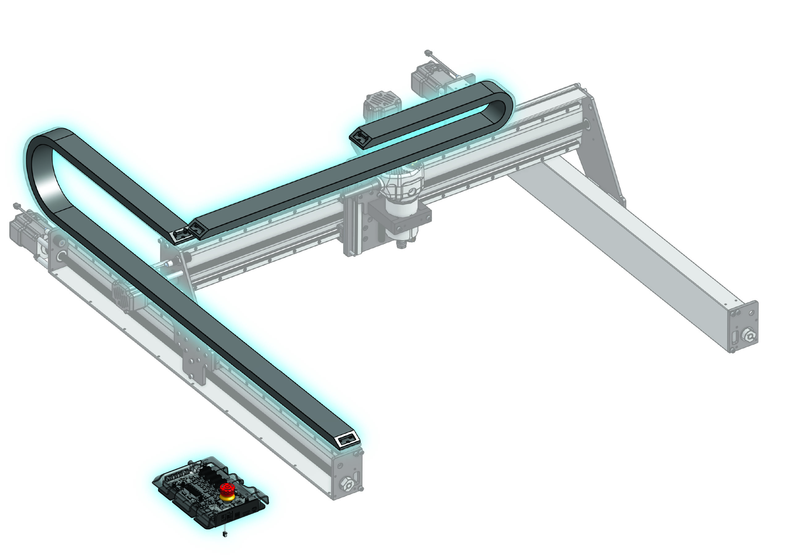
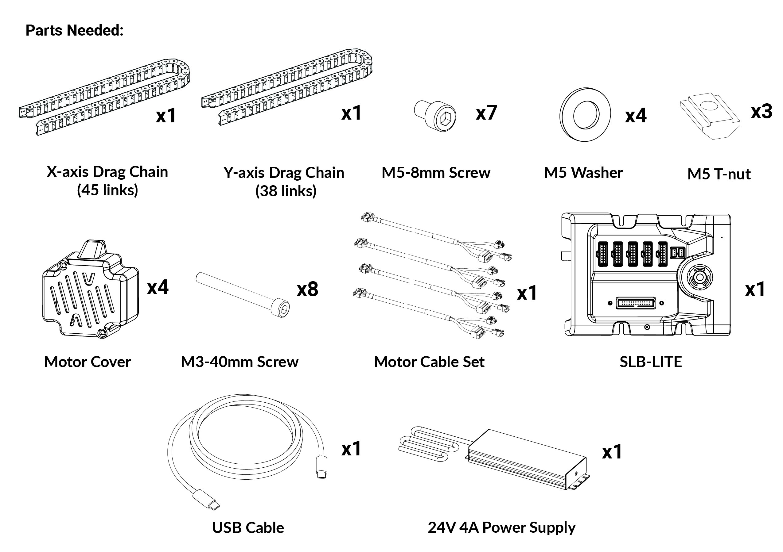
-
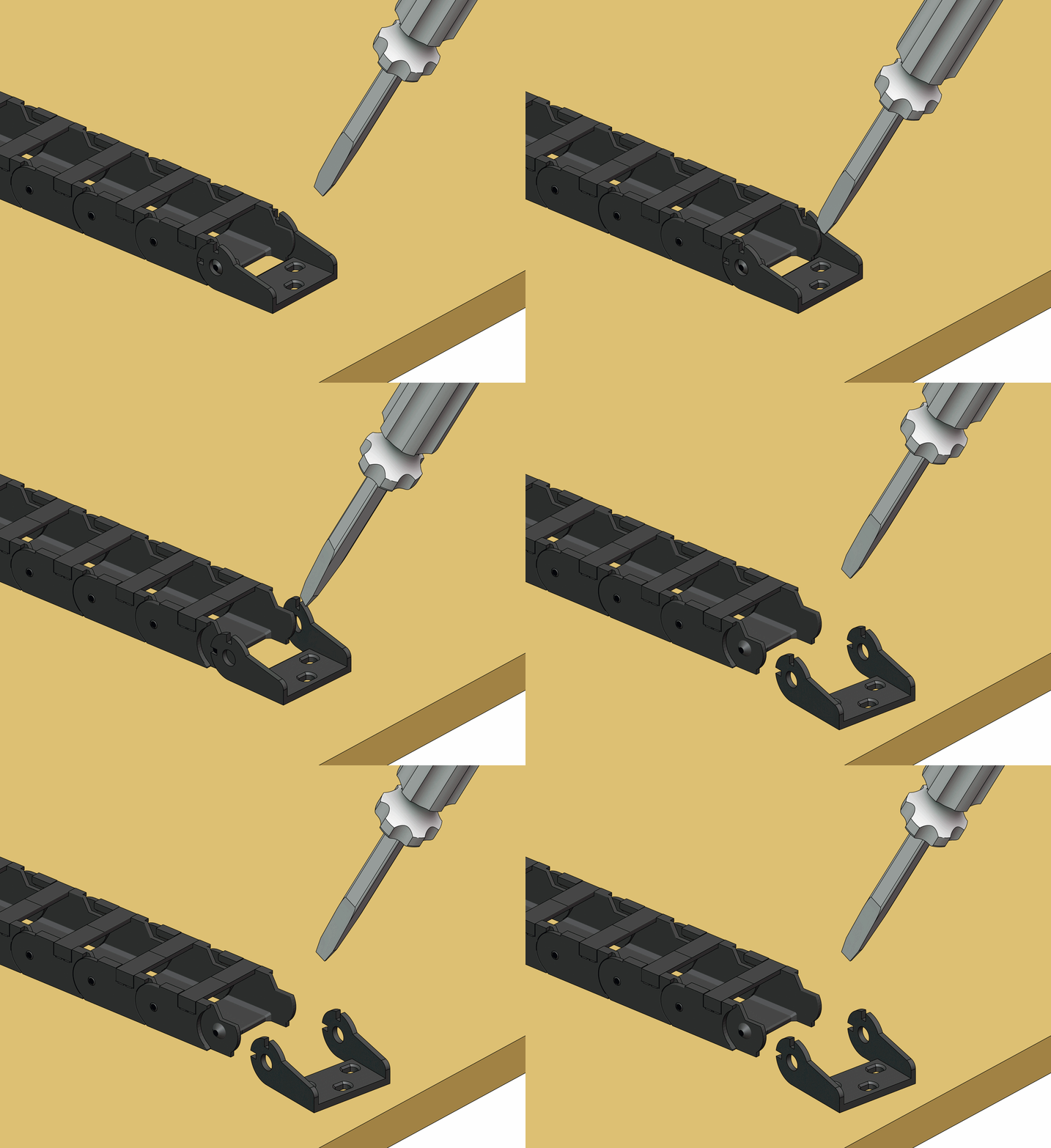
Take off the drag chain end links using a flat head screwdriver. There should be four (4) total, two (2) with studs and two (2) with holes at the tabs.
-
For the X-axis drag chain, if you have the 30×30, remove 7 links.
-
Assemble the drag chain ends with fasteners onto the machine, matching the orientation shown in the images. The fasteners should be hand tight, do not overtighten or the end links could break.
Left side of X-axis:
- Two (2) end links with holes
- Use M5-8mm screws and M5 T-nuts
- T-nuts should be inserted with the smaller face inside the T-slot
- Align the left-most end link to the center of the Y rail
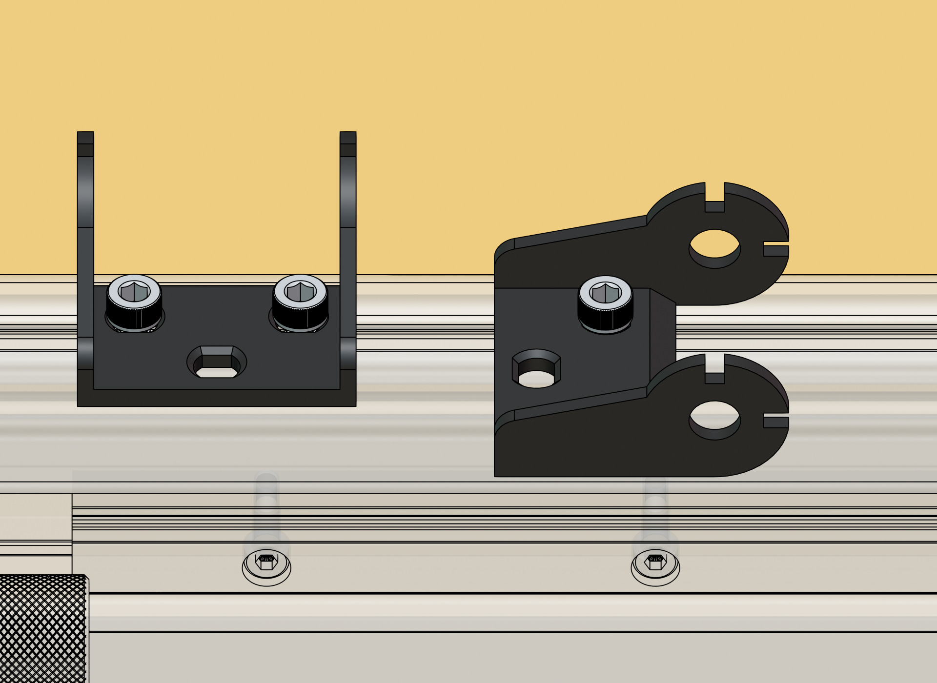
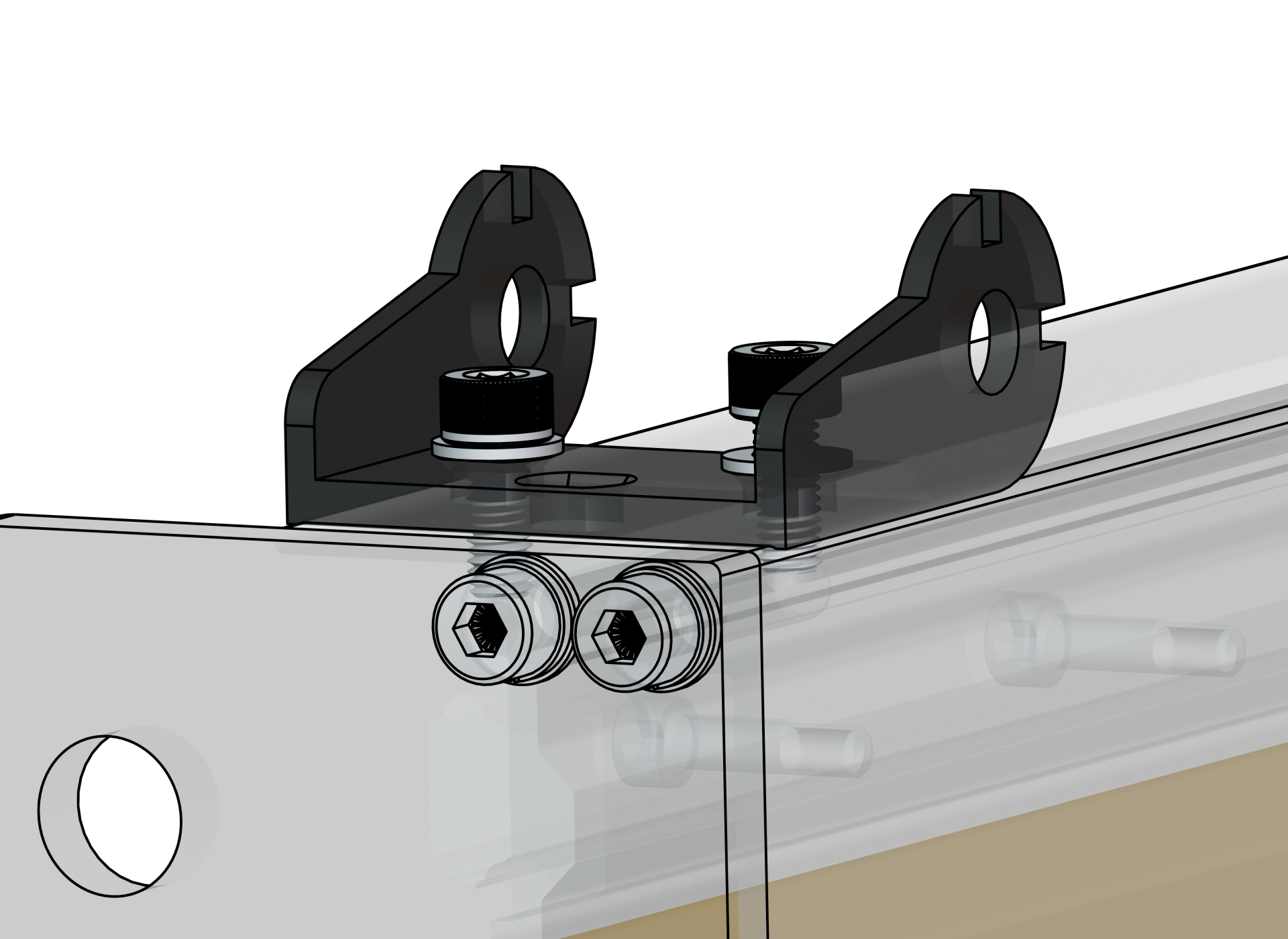
Left Y-axis, front of machine:
- One (1) end link with studs
- Use M5-8mm screws, and M5 washers under the screw head
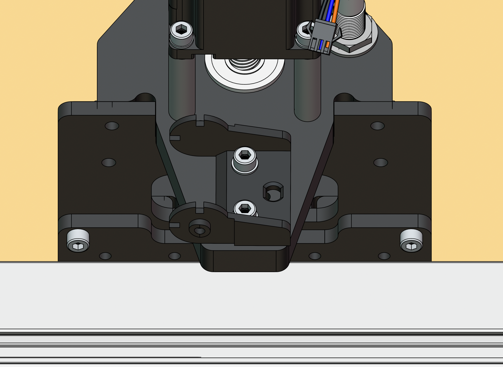
Z motor mount, behind Z-axis:
- One (1) end link with studs
- Use M5-8mm screws, and M5 washers under the screw head
-
Open all the clips on both drag chains, using a flathead screwdriver.
-
Place the X-axis drag chain onto the X rail.
-
Route the router cables (e.g. power and signal for AutoSpin), as well as the Z motor cable through the drag chain. As you route them, close the clips.
-
Secure the X-axis drag chain onto the end links at the Z motor mount and X-axis end link.
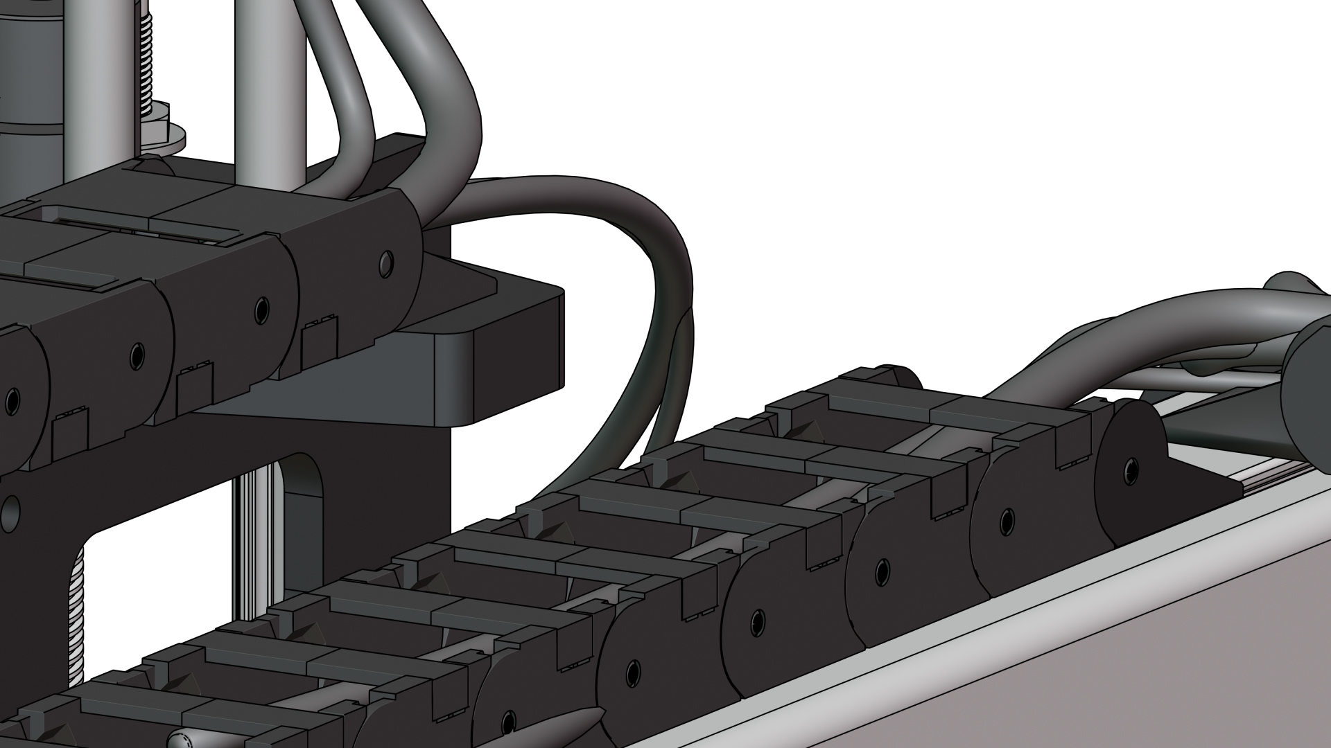
💡 Tip: If you’re having trouble putting the drag chain back on the end link, loosen the end link screws to allow for alignment. Then re-secure. -
We will now move onto the Y-axis drag chain. Connect the two pieces of drag chain together.
-
Place the drag chain on the table, to the right of the left Y-axis. This will give us more space to route the cables.
-
Route the cables coming out from the X as well as the X motor cable, exiting out to the front of the machine. As you do this, close the clips.
-
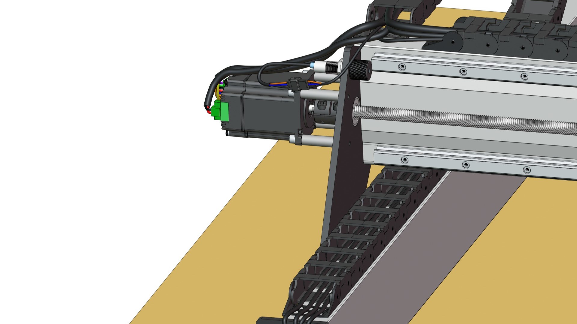
Place the drag chain onto the left Y-axis rail. Secure the drag chain onto the two (2) end links at the left side of the machine.
-
Grab the Y1 and Y2 motor cables. Make note:
- Y2 cable -> Right motor
- Y1 cable -> Left motor
-
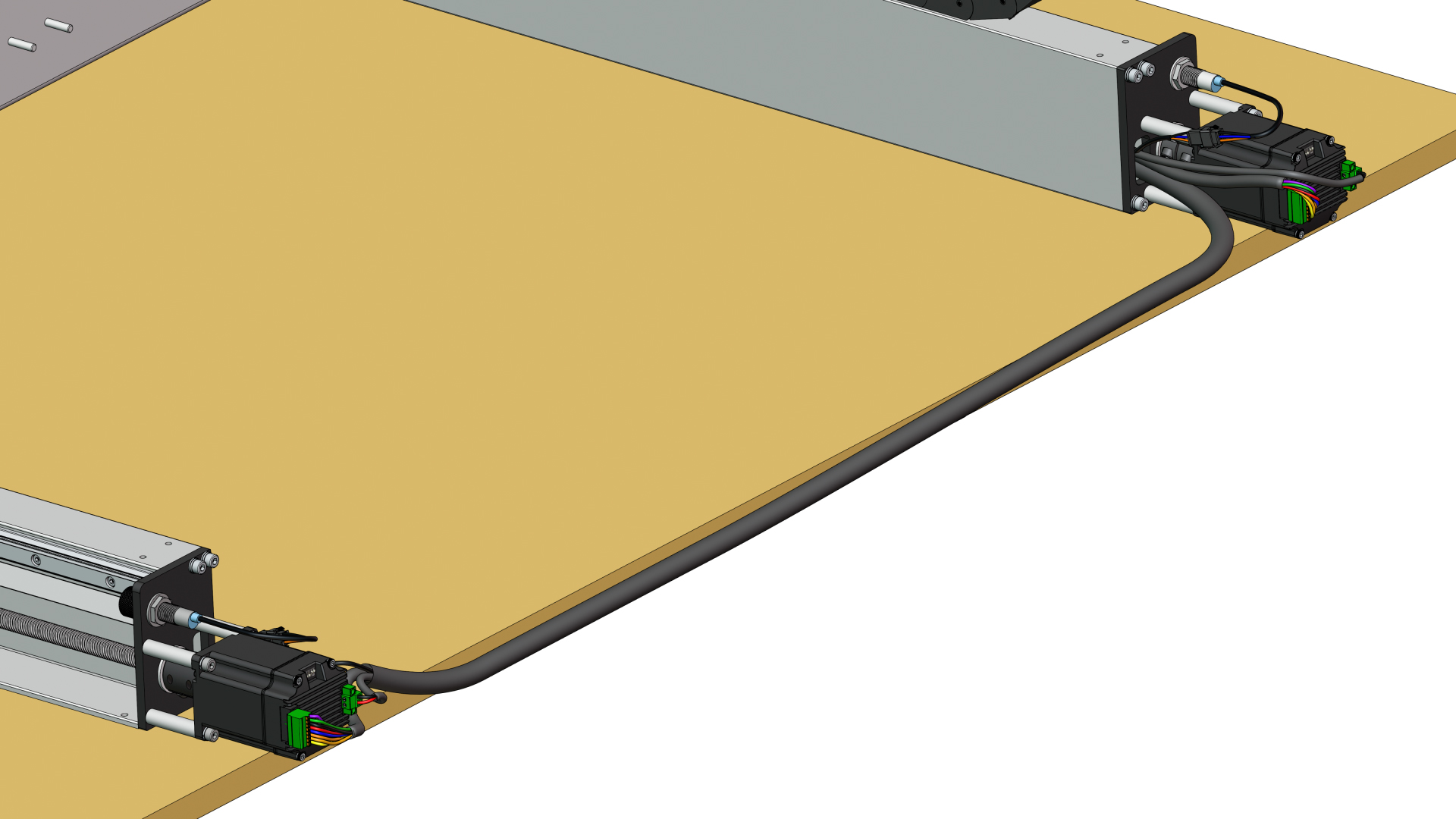
Route the Y1 and Y2 cables through the left Y-axis extrusion, making sure that the green connectors can reach the correct motor. Use needle nose pliers to grab the black connectors from the front.
-
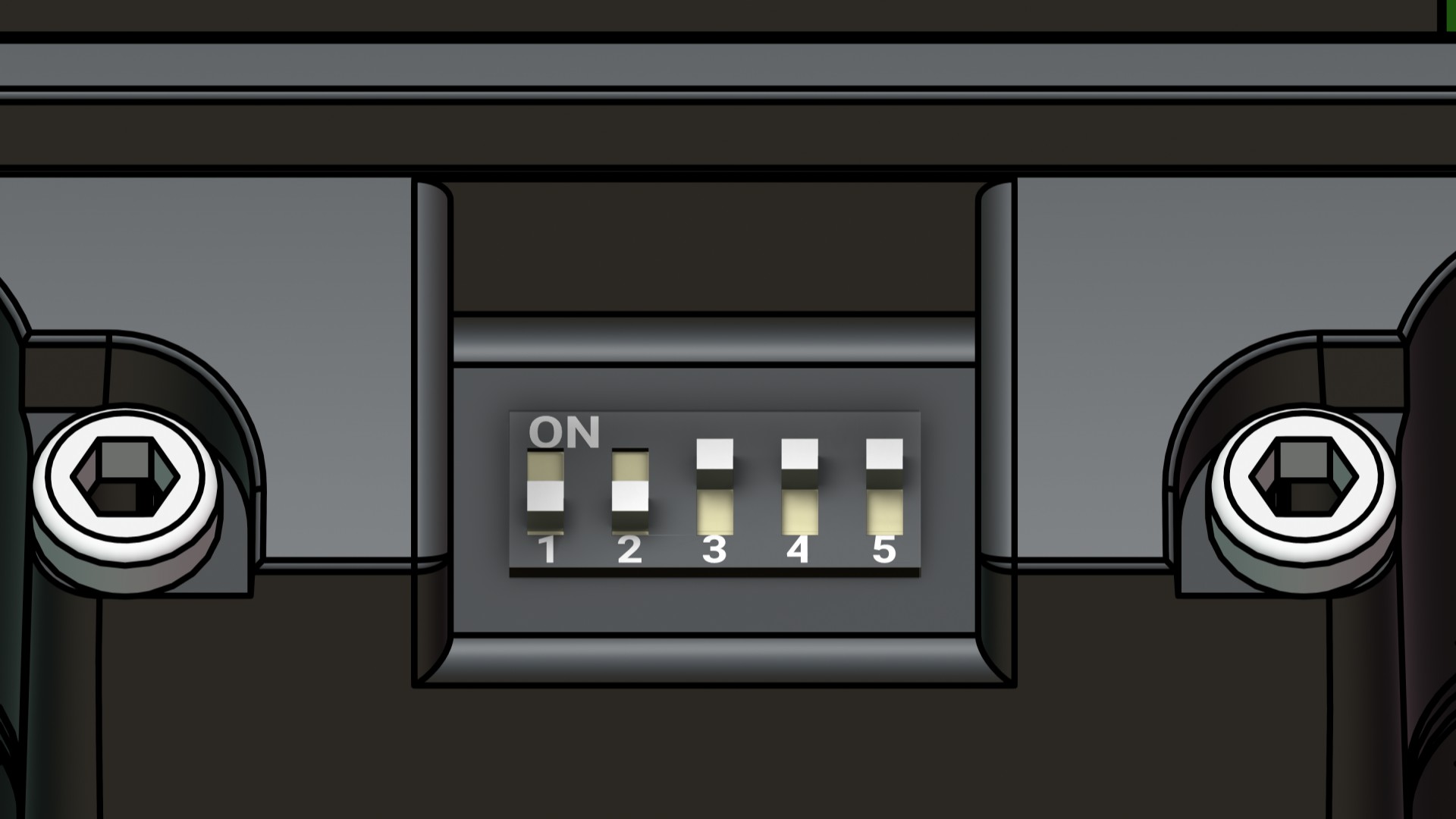
Secure wire connections at each motor – limit switch, motor power, and motor signal. Then check that all motor DIP switches are in the correct positions: 1-OFF 2-OFF 3-ON 4-ON 5-ON
-
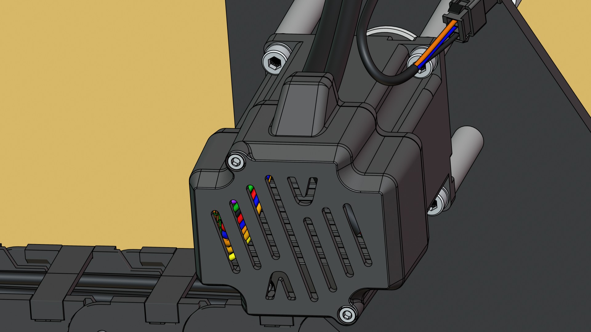
Remove two (2) screws from the back of the motor, one to the right of the DIP switch and the other diagonally at the top.
-
Place the motor covers on the motor. For the X and Y, orient them so the small opening is facing either upwards or downwards. Route the wires through the opening, to prevent damage. Then secure covers with two (2) M3-40mm socket head screws using the provided Allen key.
-
Place the SLB-LITE onto the table, at the front-left corner. You may need to push the machine closer to the right side to do this.
-
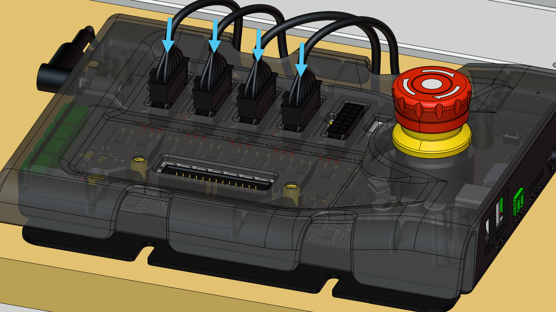
Connect the motor cable connectors for each axis as indicated on the SLB-EXT.
-
Plug the USB cable into the SLB-LITE, at the USB port.
-
Plug the power supply into the SLB-LITE, at the POWER port. Then plug the power supply into wall power (120V). We recommend putting your router into a separate circuit from the controller and computer.
-
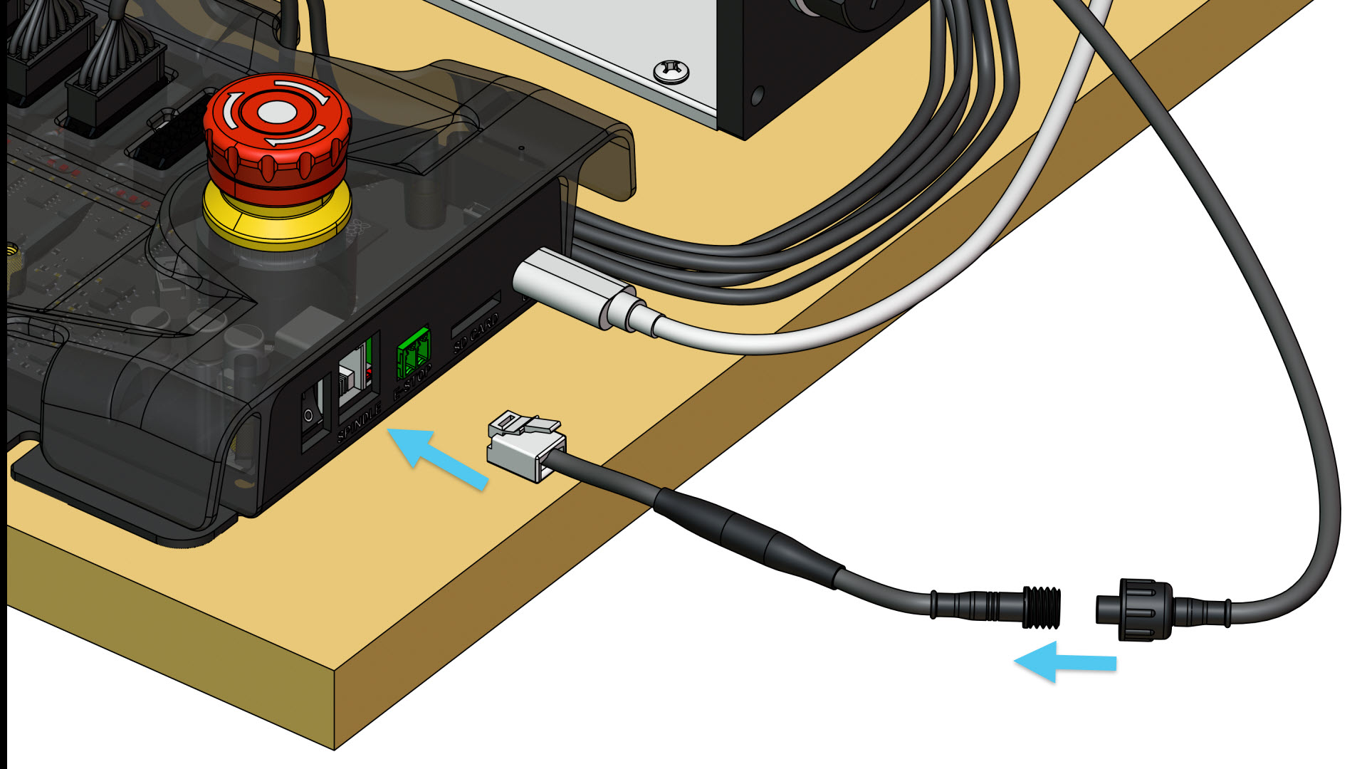
On the AutoSpin, untwist the cable with the green connector.
-
Grab the adapter cable with the ethernet connector, and twist it onto the AutoSpin Plug the ethernet connector end into the SLB-LITE, at the SPINDLE port. Then connect the power plug end into wall power.
