2. X & Y-Axes
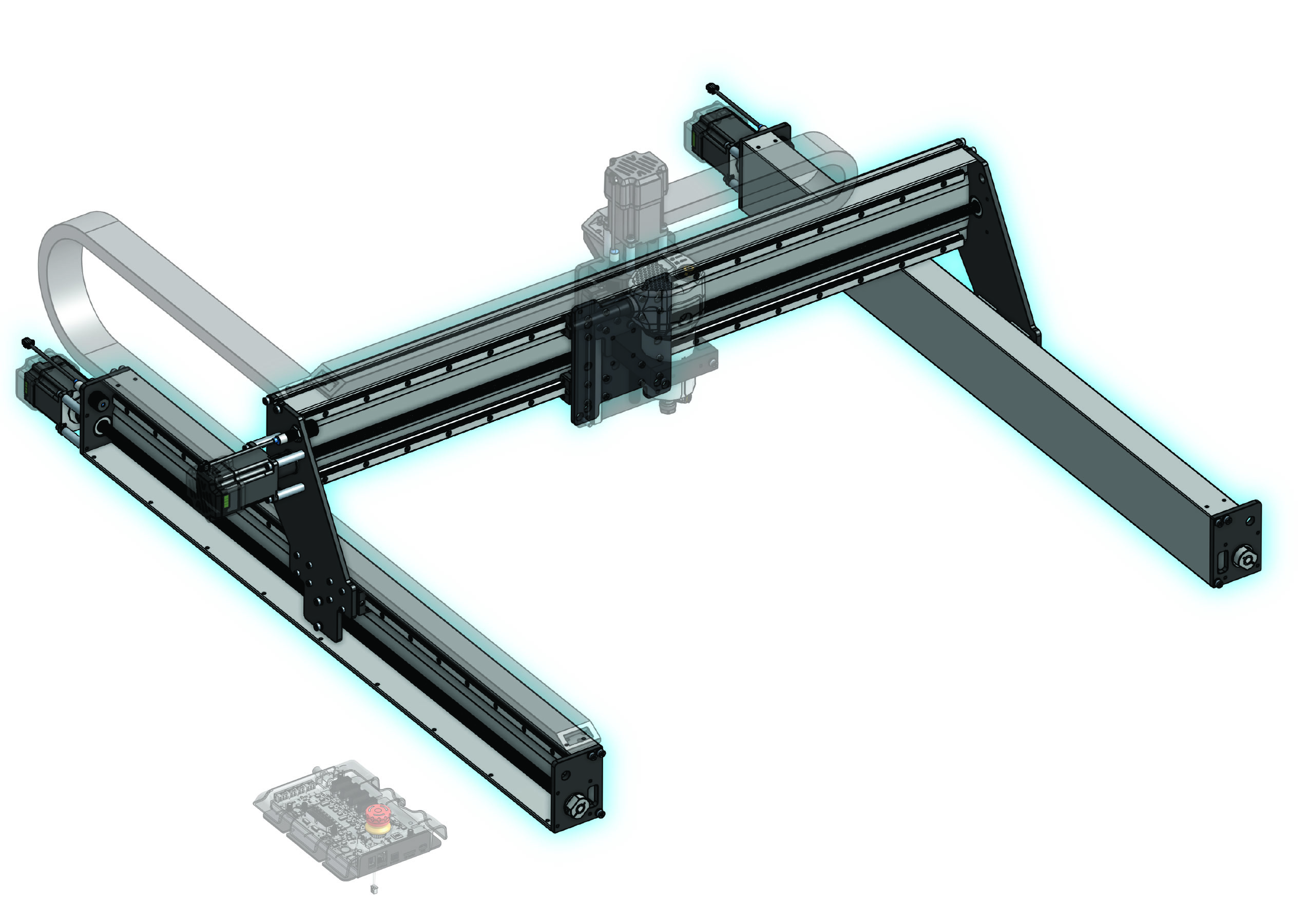
X and Y-axes
-
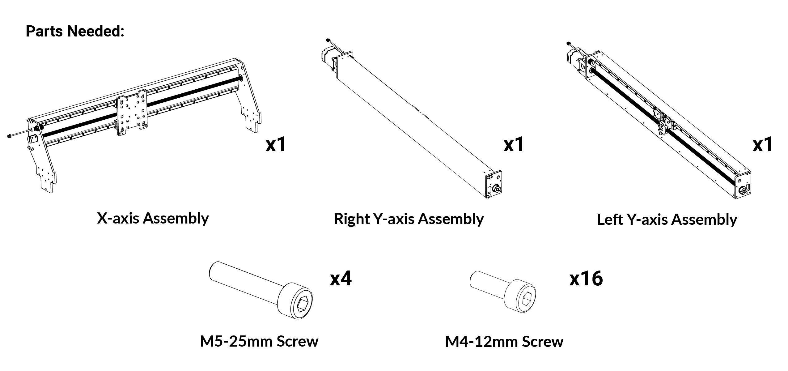
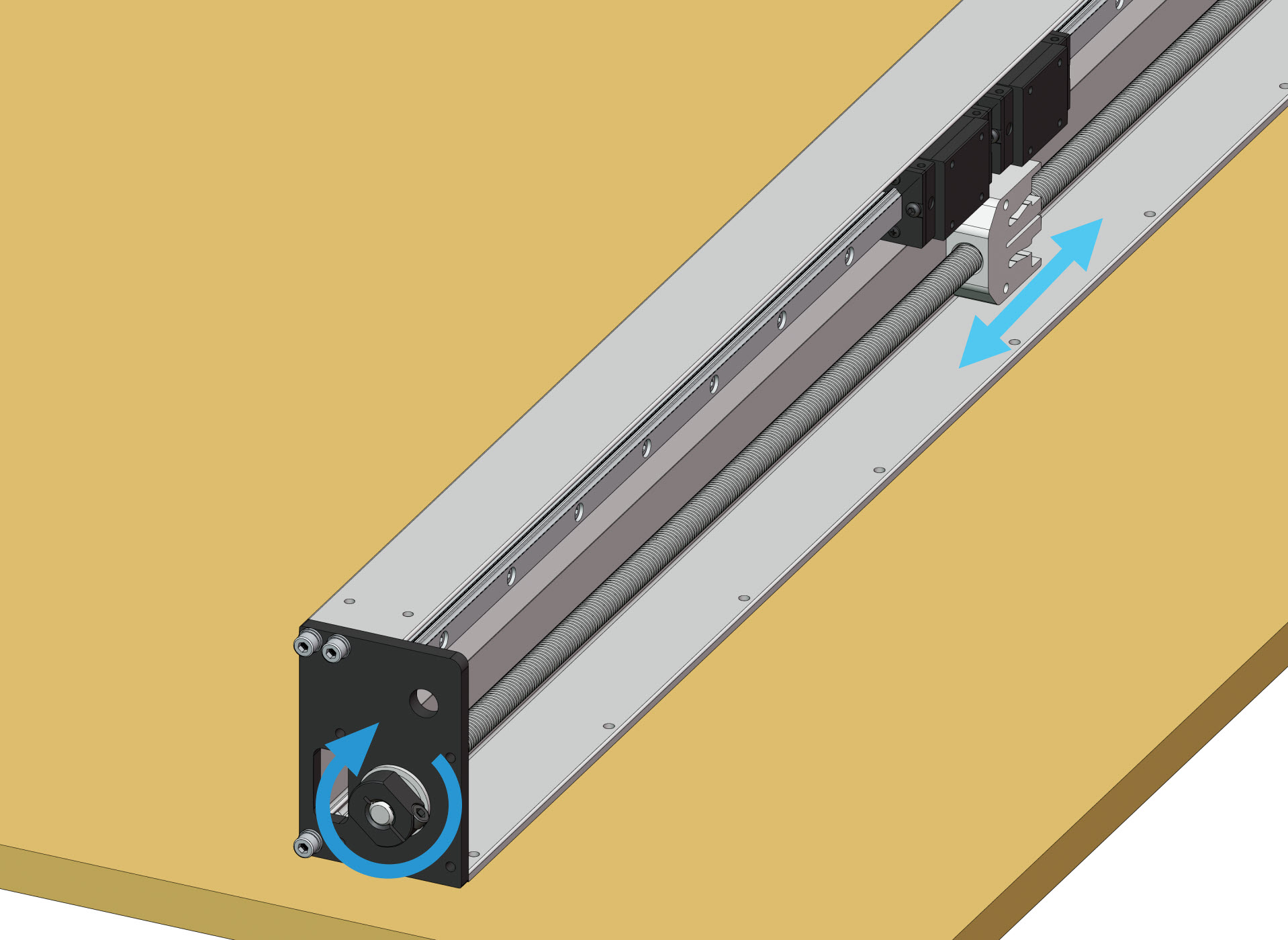
Take out the two (2) Y-axis assemblies. By hand, rotate the Y lead screws at the ACME clamping nuts to align the white anti-backlash nuts on both Y-axes. They should be spaced evenly from the front Y rail plates, at the middle of each rail.
-
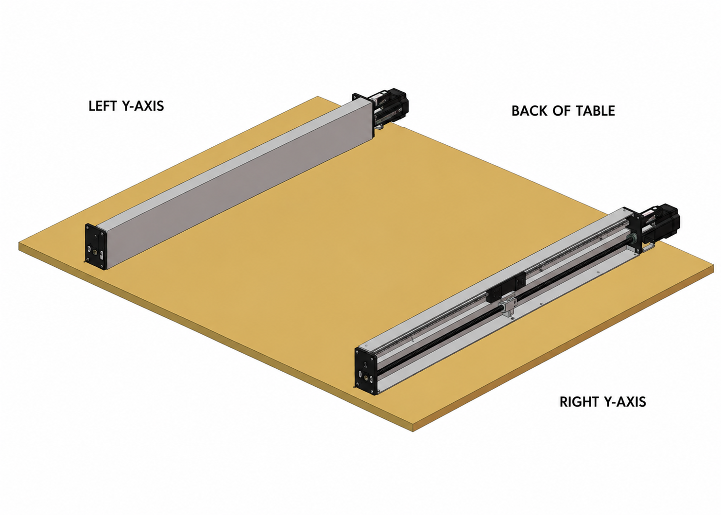
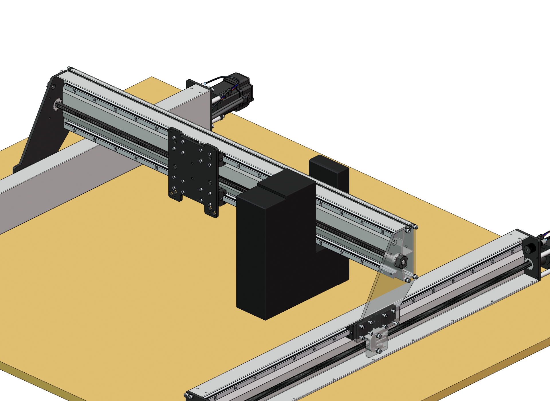
Identify between the left and right assemblies. Orient them onto your 4’x4’x3/4” MDF sheet, on top of your table, so that:
- Lead screws face outwards
- Motors face the back of table
-
We will now place the X-axis assembly onto the Y-axis assemblies. Grab a friend, OR take out the Y gantry packing foam.
-
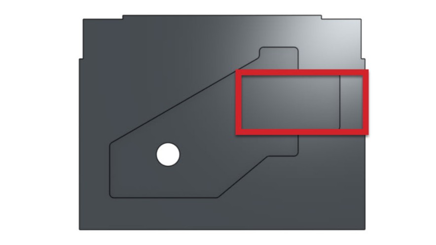
Cut a rectangle in the Y gantry packaging foam (outlined in red) so you can use it to hold the X-axis assembly upright. Move the assemblies so that the Y gantries are over top the anti-backlash nuts.
-
Check that the holes on the linear guide blocks and anti-backlash nuts are aligned with the gantry holes. Move the blocks as needed.
-
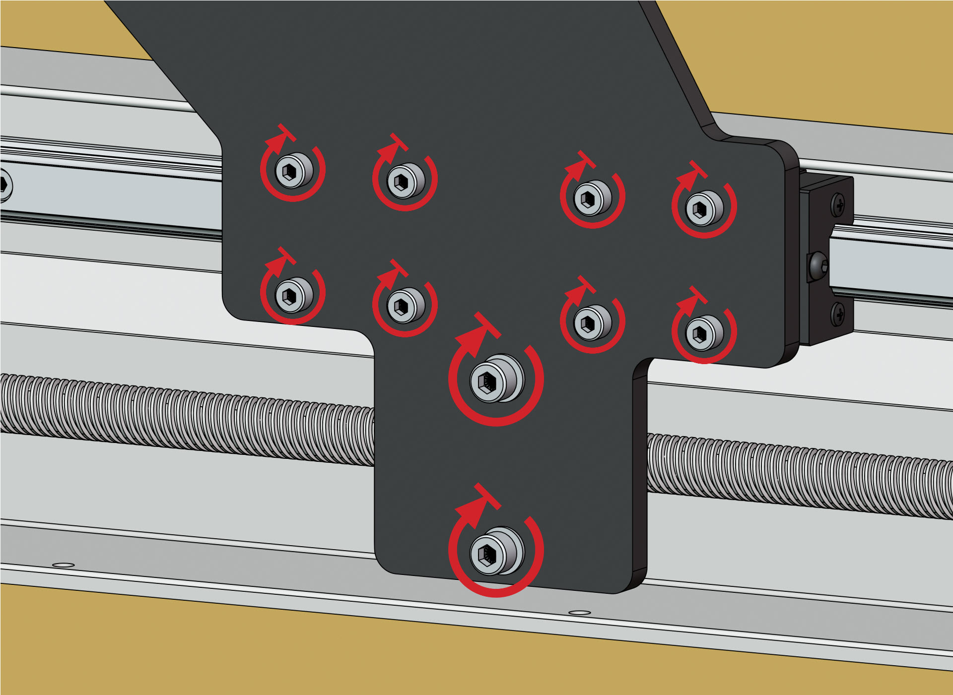
Put in two (2) M4-12mm screws into the bottom holes of the linear guide blocks, where the notches are on the gantry.
-
Secure the remaining M4-12mm screws onto the linear guide blocks in a diagonal pattern.
-
Secure the two (2) M5-25mm screws to connect the anti-backlash nut with the Y gantry. Only tighten until you feel resistance – do not overtorque these.
-
Repeat securing the anti-backlash nut and linear guide blocks on the other side.
-
Remove the foam from under the X-axis assembly, if you used it.
X-axis Motor
-
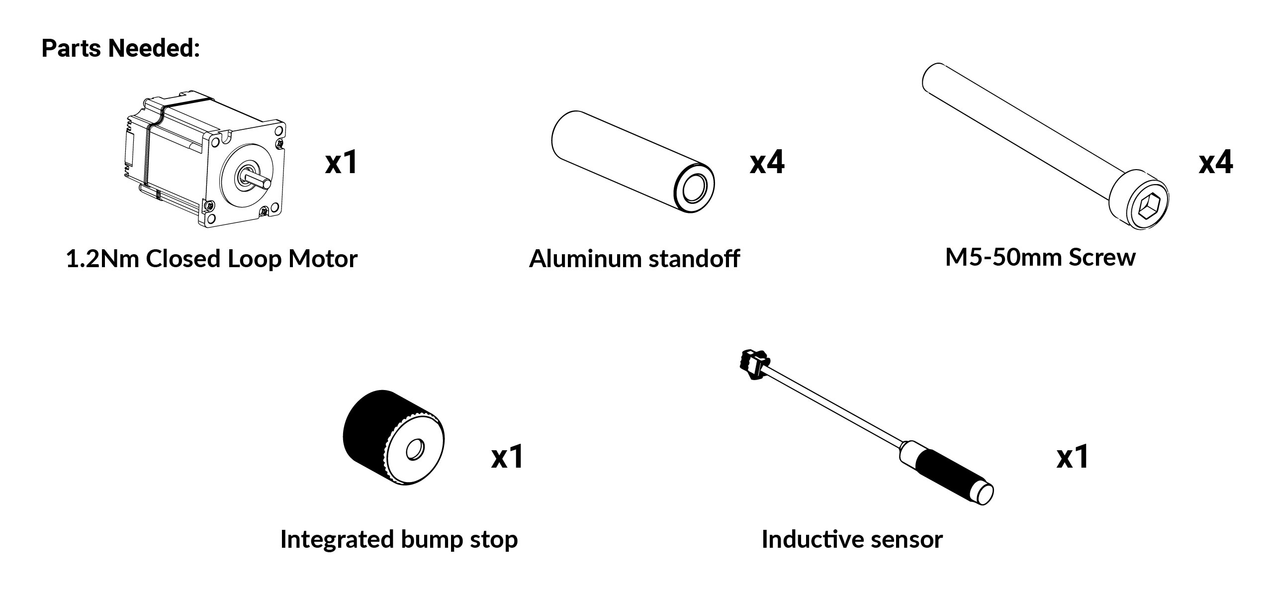
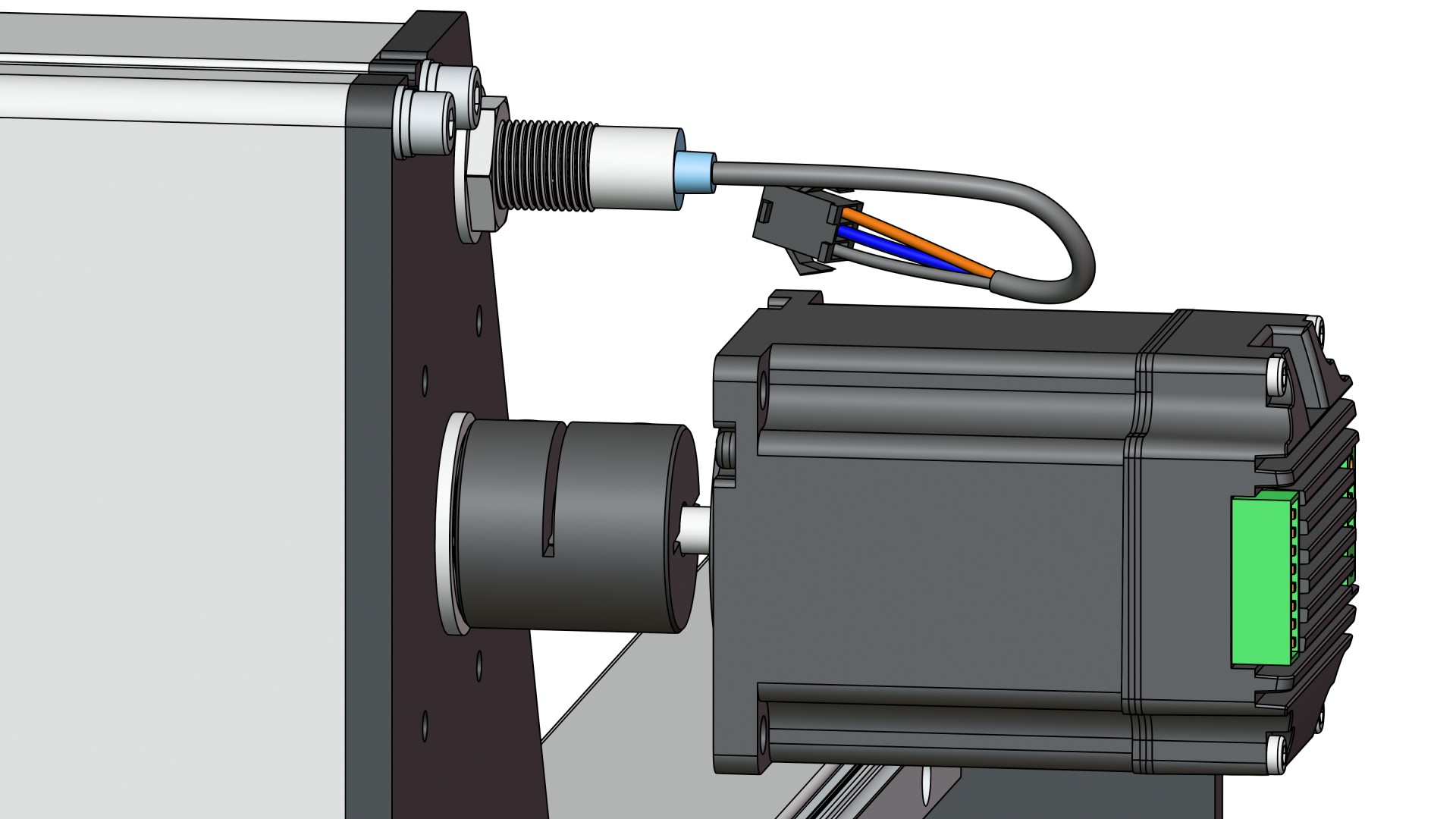
Loosely insert the motor onto the X-axis coupler at the left side of the machine.
-
Then place one (1) standoff between the motor and Y gantry.
-
Loosely fasten one (1) M5-50mm screw through the motor and the standoff, into the Y-gantry. Repeat this for the remaining three (3) holes.
-
Then fully secure the M5-50mm screws until snug.
-
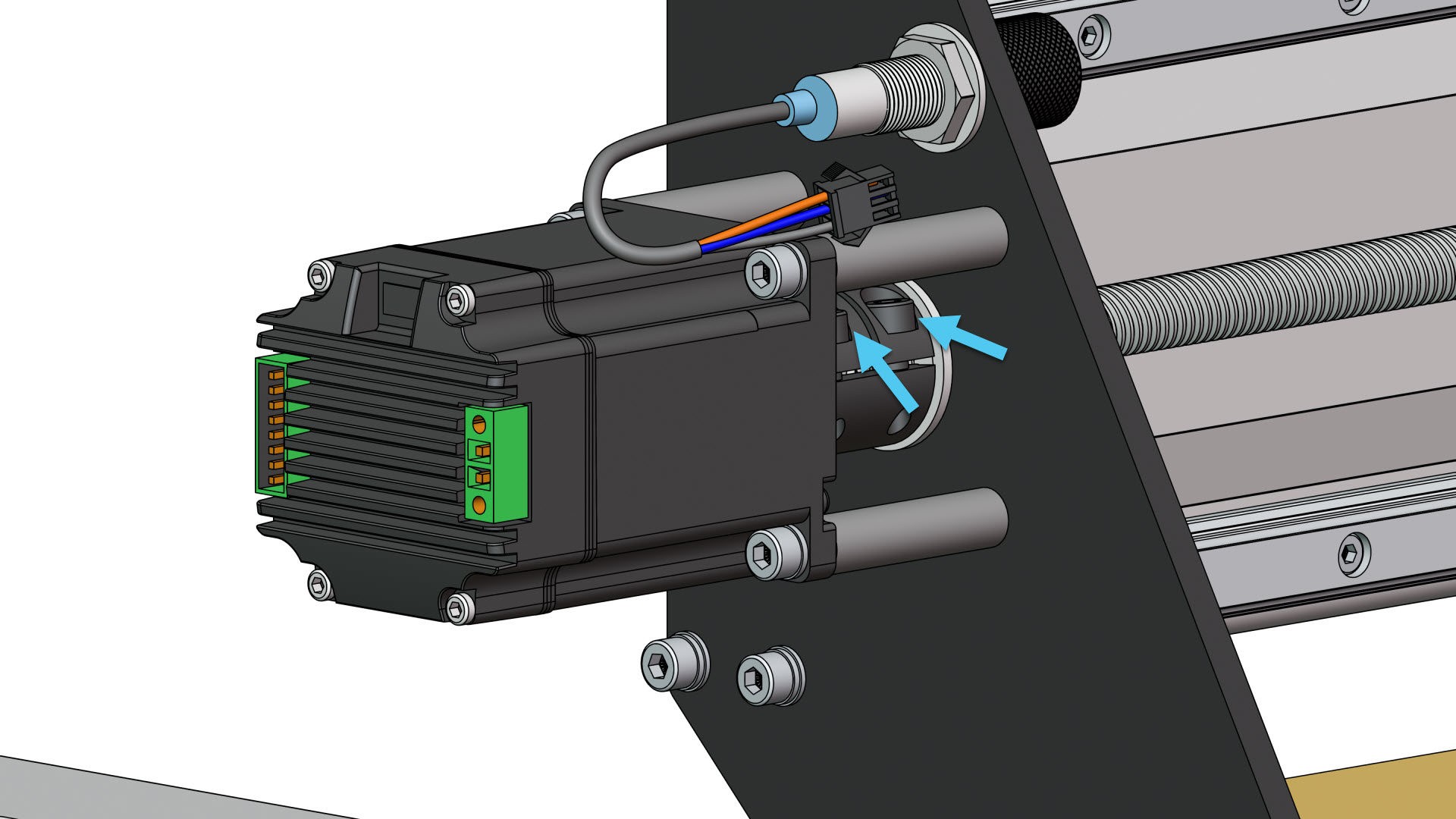
Finally, tightly secure the coupler setscrews.
-
Prepare one inductive sensor by threading a nut onto it approximately 45mm / 1.5 inches from the front, and add a lock washer from the front.
-
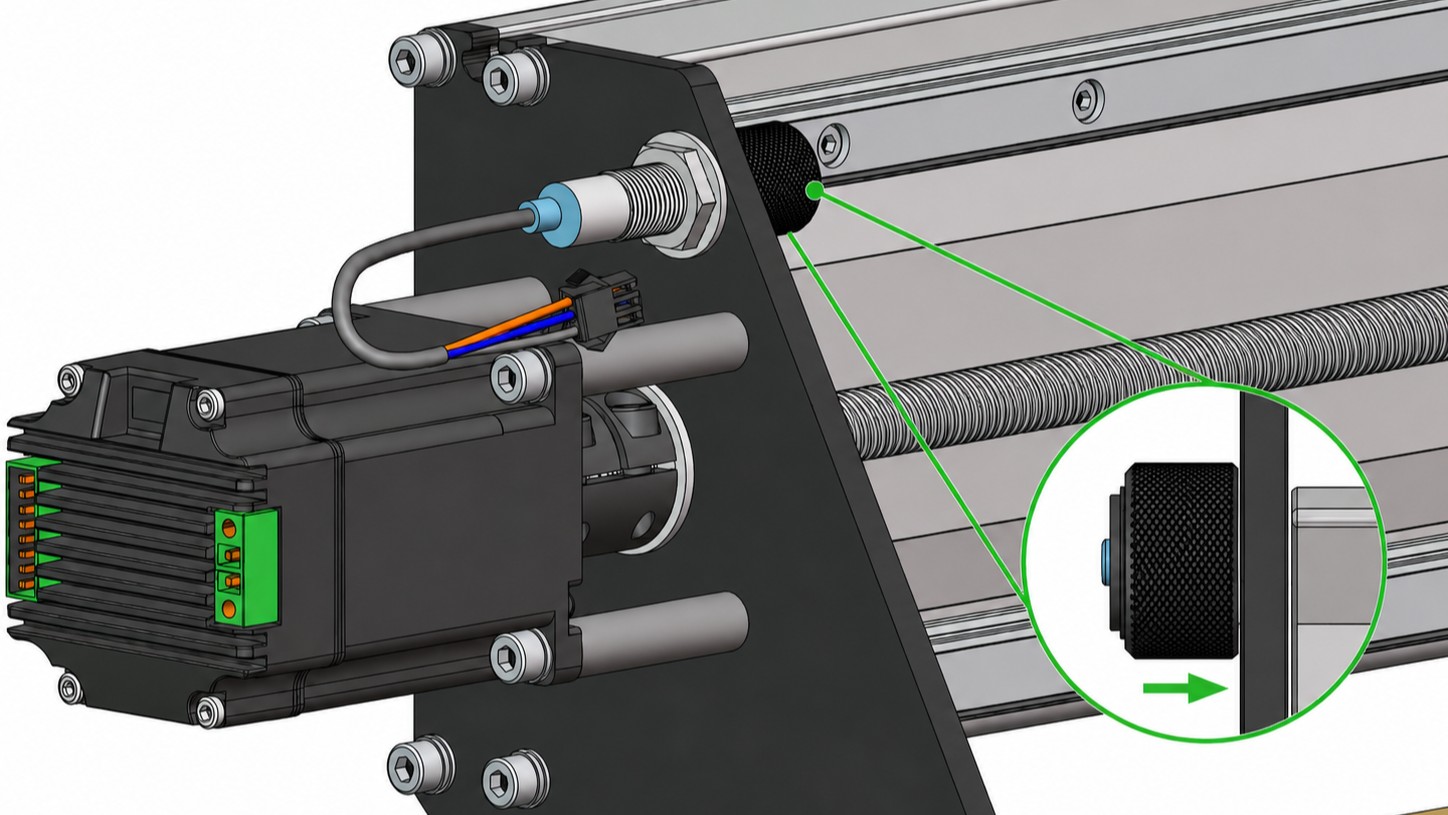
Pass this inductive sensor through the hole on the left Y-axis gantry plate, and thread the bump stop over the end of the sensor until it bottoms out. Hand tighten until snug.
-
Secure the nut and lock washer against the gantry plate – it is important that this sensor is fully seated in the bump stop.
💡 Tip: If adjusting the motor, tighten the coupler first, then tighten down the motor standoffs.