Firmware & Flashing
Your board will likely ship with the latest firmware already installed, but we occasionally make updates to add new features or address any discovered issues. You may also choose to re-flash the firmware onto your board if you’ve attempted to customize it or for troubleshooting purposes.
Do not flash your SLB unless you’ve done it before and are absolutely sure you know what you’re doing or are being guided by our team. The flashing process can be touchy the first time, so if you’re having problems then please contact our team first otherwise be prepared to accept a regretful outcome.
Before getting started, check what your current version is by going to the ‘Console’ of your g-code sender and send the command $i. The result will be a long list of text in square brackets. If you scroll down to about the 9th line you’ll see something like “[BOARD:” where you’ll also see the version number at the end. Compare this to the version list below to see which one you’d like to flash:
Most Recent Firmware:
- SLB: 5.0.5b
- Updated default A-axis step/mm to match typical Vortex setups using 32nd microstepping
- Updated defaults to accommodate some machine setups that couldn’t handle the max speeds and accelerations of the SLB
- Changed min spindle speed, spindle on delay, and default enabled spindles to match typical spindle setups using the SLB
- SLB EXT (AltMill): 5.0.11
Flashing Summary
To successfully flash new firmware onto your SLB, you’ll need:
- The firmware file; all versions are listed above as “.hex” files to download
- A computer that can run either gSender or the STM Cube Programmer software to perform the flashing
- The SLB connected to that computer over USB (you can’t flash over Ethernet because the MCU on the SLB can’t support it, but you can return to using your Ethernet connection once flashing is complete)
- A 12-24V power supply to power the SLB during flashing
- Have separately noted down any firmware settings that are particular to your machine setup like for limit switches, macros, etc. New firmware can sometimes override existing settings so having a list can help you double check if you need to make any manual tweaks afterwards.
- For your safety, if there are any accessories that receive a control signal from the SLB, turn their power off just in case the flashing process inadvertently sends control signals to those accessories. This would be unsafe to have a spindle or laser power on when you don’t expect it to. You can turn these back on after flashing is complete.
You can choose to either use gSender or the STM Cube Programmer software to update your SLB, the steps for either option are below:
gSender Flashing
-
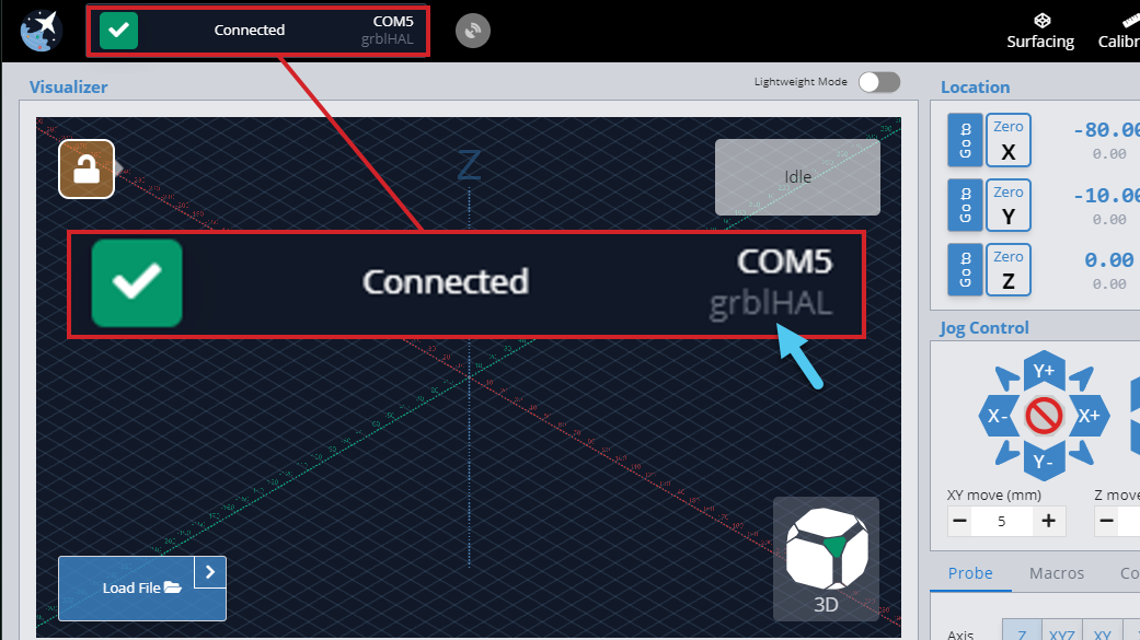
Be connected to your SLB over USB with the power on, ensure the firmware selected is ‘grblHAL’ not ‘grbl’
-
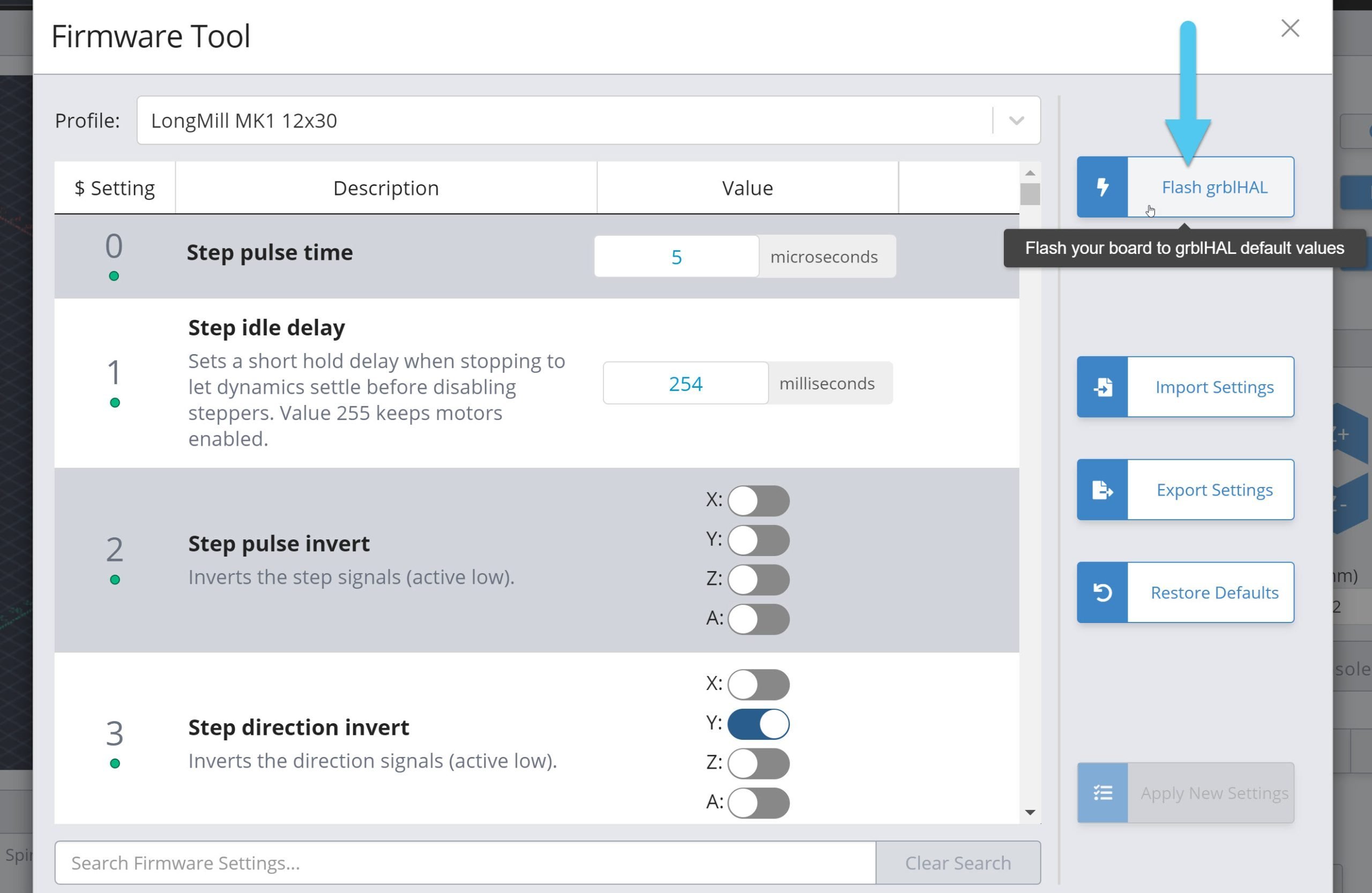
Go to the ‘Firmware’ tool and click the ‘Flash grblHAL’ button
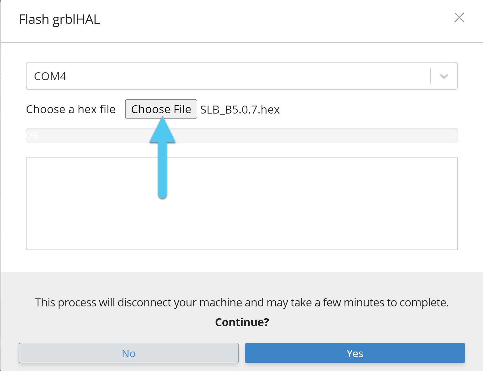
- Ensure the COM port is correct (matches the board you’re connected to)
- Click ‘Choose File’ to select the “.hex” firmware file you plan to update to, in the picture below it’s the 5.0.7 firmware
-
Click ‘Yes’ to begin the flashing process. If it stops before 100% and you see an error for:
- “LIBUSB_ERROR_NOT_SUPPORTED”, you’ll need to update your Windows driver
- “Unable to find valid device”, you might have installed your Windows drivers incorrectly
- “LIBUSB_ERROR_ACCESS”, your Ubuntu device might be having a USB rights issue
-
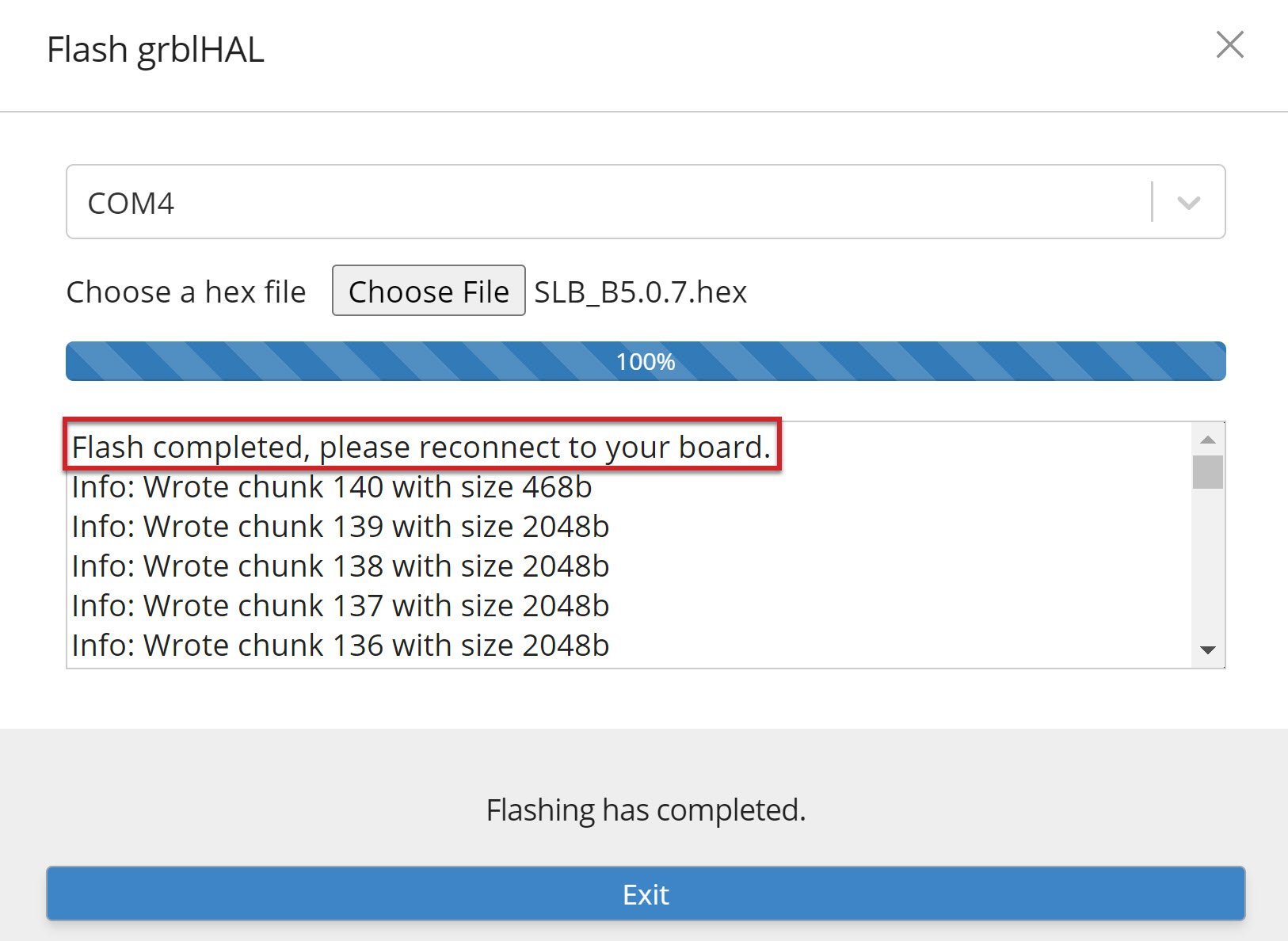
Once you see the loading bar at 100%, flashing is complete. Exit out of the firmware window and switch off the board with the power switch at the back then turn it back on again.
-
Once it’s back on, you should be able to re-connect to it in gSender. Go to the ‘Console’ tab and send the command
$rst=$to revert your machine back to the default firmware settings (you shouldn’t get any errors when you send this command).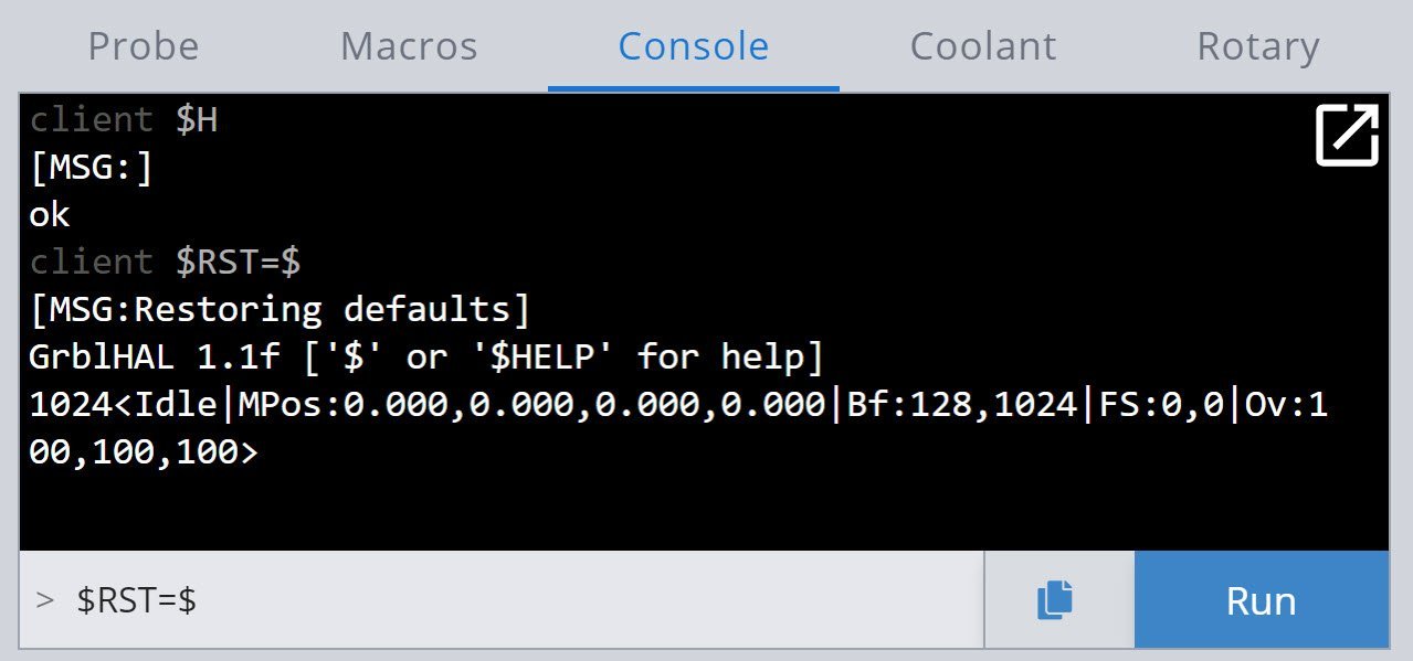
- Power the board off and then back on one more time after sending the command. Finally, if you had any specific settings from your previous setup that you want to check or reload, connect back to gSender and change those firmware values back. Remember to hit “Apply New Settings” when you’re doing this and ensure that the settings are being re-added correctly, if they don’t seem to be sticking then make sure that your SLB is in an ‘Idle’ state, cleared of all Alarms, and try turning the SLB off and back on again.
Congrats are in order, well done! If you go back to the ‘Console’ you should now see that sending the $i command will give you new text that matches up with the update you’ve made.
STM Cube Flashing
Download the software from here (this is version 2.15.0) or for another OS go to STM’s website.
- On the SLB, switch off the power toggle switch at the black of the board or unplug it from power
- Use a jumper or metal tipped tool like a screwdriver or Allen key to short the BOOT pin (shown) and hold it in place
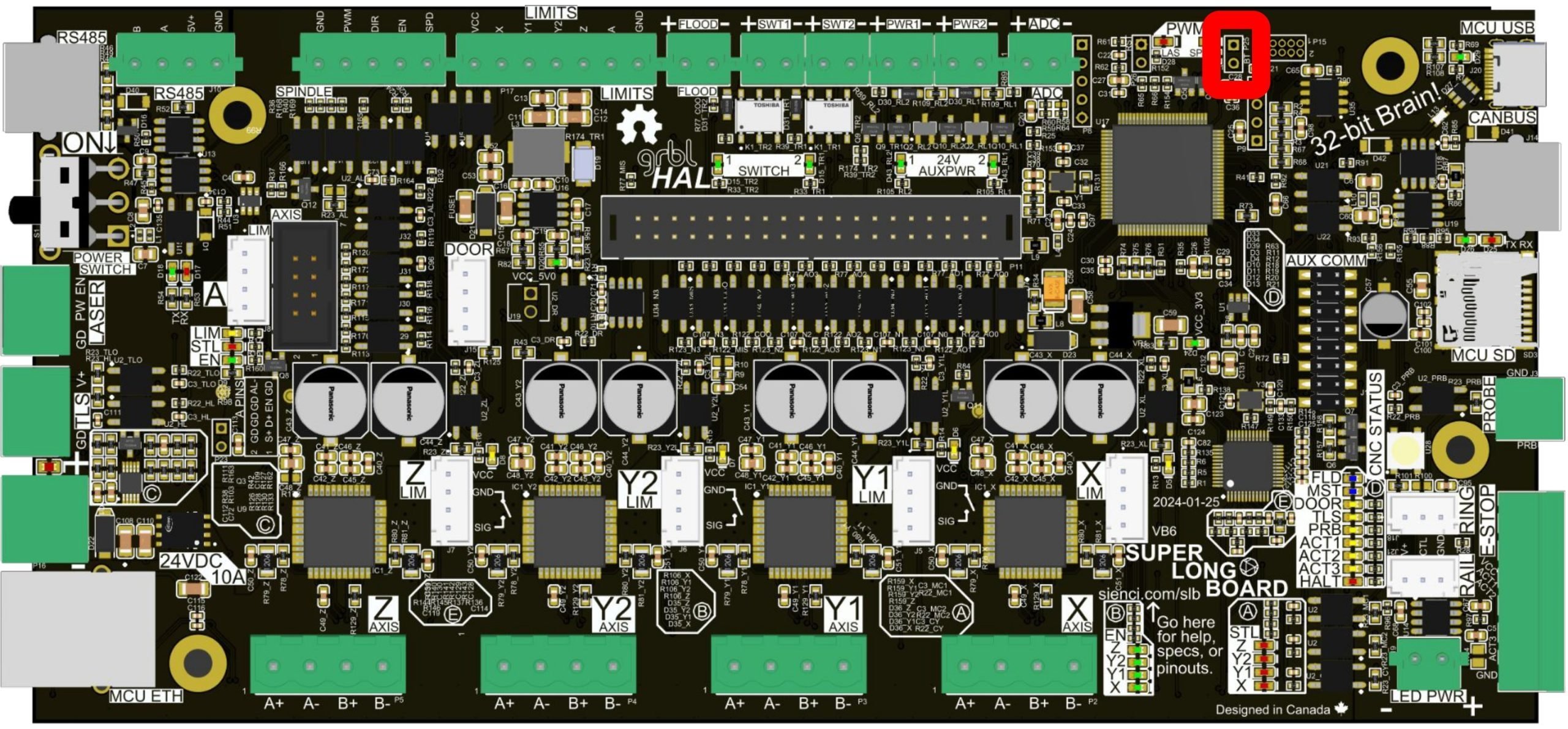
- Now turn the SLBs power toggle switch back on or reconnect power. You should see that most LEDs on the board are turned off now, especially the main Status LED.
- You can remove or let go of the BOOT jumper now.
-
With the STM32 Cube Programmer opened on your computer:
- Select ‘USB’ in the blue drop down box at the top of the right of the window
- Click the refresh button next to ‘Port’, the board will typically show up as “USB1”
- If the board shows up, press the green ‘Connect’ button. If you still see “No DFU”, check your setup then click the refresh button again
- Go to the ‘Erasing & Programming’ tab on the left side of the screen
- Select the blue ‘Browse’ button to select the latest hex file (firmware file) on your computer
- Press the blue ‘Start Programming’ button
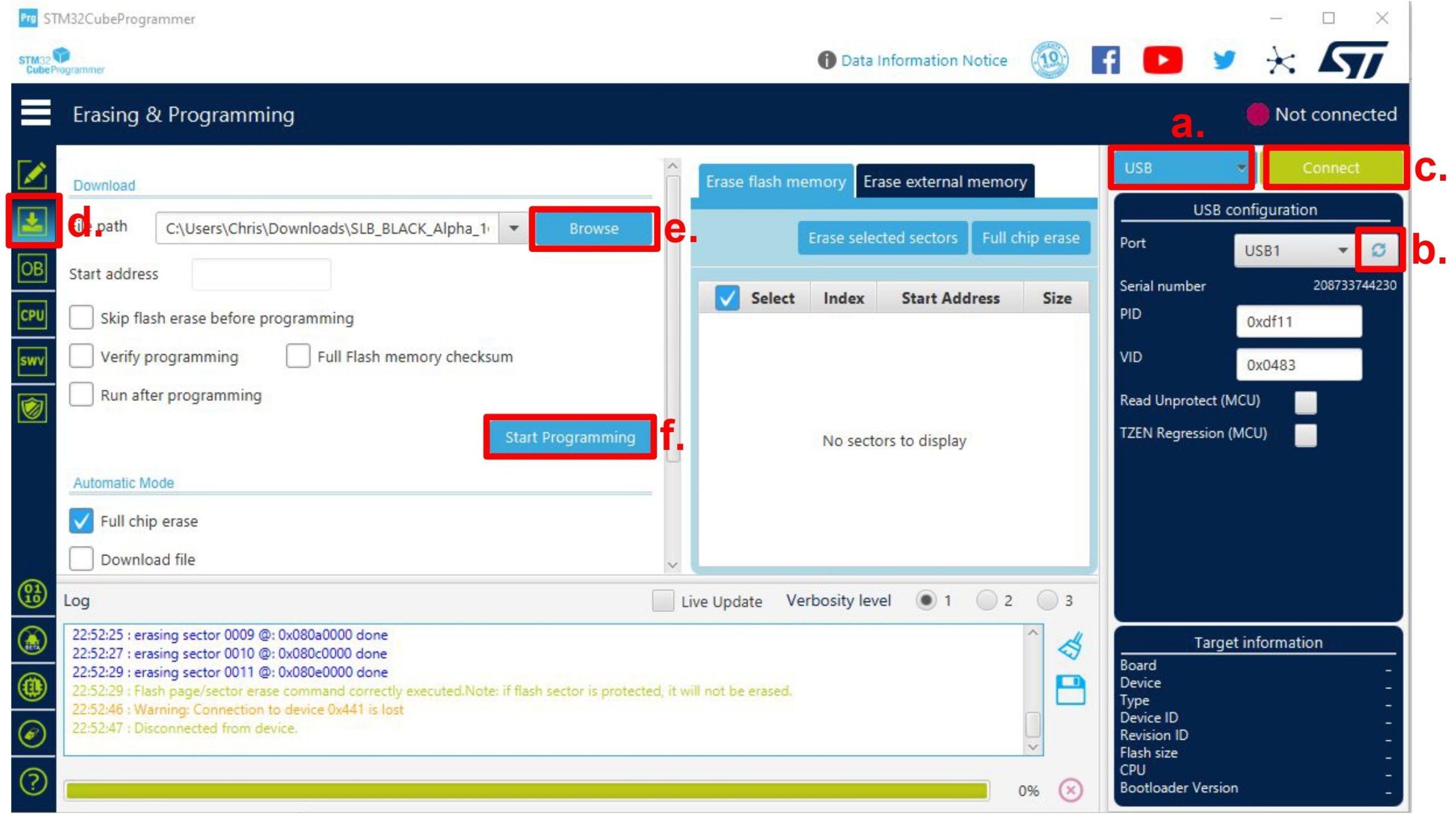
- Once complete, you’ll have to exit out of a bunch of small windows
- Switch off the board power switch then turn back on again, then reconnect to the board in gSender, ioSender, or any other g-code sender.
- Follow the same last 2 steps (7 and 8) of the gSender Flashing process and you should be done!
Windows Driver Update
If you’re failing to update your SLBs firmware and see the message “Error: LIBUSB_ERROR_NOT_SUPPORTED”, this stems from the sometimes problematic way that Windows handles USB devices. This isn’t a problem for Linux or Mac systems, but if your Windows computer is having this issue it can still be fixed by overriding the wrong driver it’s using with the correct one.
To do this we’ll use a program called Zadig. The program is only needed to make the fix, which should permanently fix SLB flashing issues:
- Download Zadig at https://zadig.akeo.ie/# (there’s an alternate download here).
- Put the SLB into DFU mode. There is two methods for this:
- Connect to the SLB in gSender and type
$dfuin the Console tab. This will disconnect it from gSender and it will no longer appear in the dropdown connection area. This step needs to happen successfully, if you get an error, assess your setup and do not move on to the next step. - Or use a jumper, flathead screwdriver, or other small piece of metal to short between two pins on the SLB near the USB port. The two pins will have “SPIN” written near them, and you’ll need to be shorting them while you use the power toggle switch to turn the SLB on.
- Connect to the SLB in gSender and type
- Open Zadig and in the toolbar click ‘Options’ ➜ ‘List all Devices’
- In the main dropdown, find and select the “STM32 Bootloader” device. This name might change depending on your current operating system.
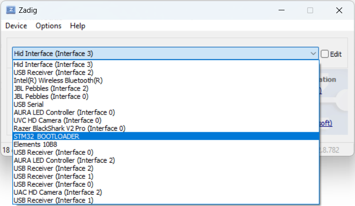
- Make sure that “WinUSB” is the selected driver type.
- Click the “Replace Driver” button and wait for the operation to complete (if you happen to accidentally delete other drivers in the process, restarting your computer should bring them back).
- Power cycle the board to exit DFU mode, then give flashing another shot. If you followed all the steps you should now be able to change and update your SLBs firmware!
Bad Driver Install
If you got the error message “Unable to find valid device using vendor ID and product ID” and you just fixed your Windows drivers then that means you made a mistake in the driver update steps. If you weren’t messing with drivers, then just ensure your SLB is getting into DFU mode by typing $dfu into a g-code sender console or using the pin short method shown in the STM Cube Flashing section.
To fix the Windows driver:
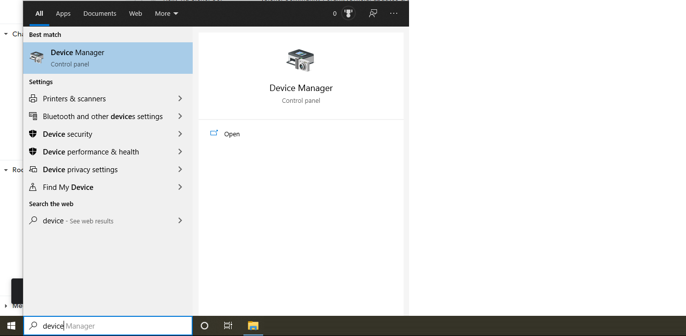
- Open ‘Device Manager‘ in your Windows start menu
- Look under the ‘Ports‘ or ‘Universal Serial Bus‘ headings for the SLB which should include “STM32” in the name
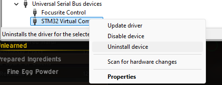
- Right-click ➜ Uninstall device, then power cycle the board
- Once powered back up and reconnected, the SLB should reappear looking more normal. With this done, you can try flashing again – or if Windows still didn’t install the correct driver then go through the Windows Driver Update again.

- If this still doesn’t seem to work, you might’ve deleted the standard STM driver while using Zadig since the SLB wasn’t in DFU mode. In this case go to STMs website to re-download the drivers (they should work even though they say they’re for Windows 7) then try flashing again.
Settings Descriptions
If you’d like to know all the ins and outs of the SLB’s firmware, and broader settings of grblHAL as a whole, you’ll find it all in the tables below.
For added clarity, settings that are currently unused on the SLB have been highlighted in orange. Also, the ones highlighted in blue though they are supported we don’t advise changing or are still building up documentation on.
| $ | Name | Value (number) | Units | Description | How to Use |
|---|---|---|---|---|---|
| $0 | Step pulse time | 5 | microseconds | Sets time length per step. Minimum 2 microseconds.
This needs to be reduced from the default value of 10 when max. step rates exceed approximately 80 kHz. |
|
| $1 | Step idle delay | 254 | milliseconds | Sets a short hold delay when stopping to let dynamics settle before disabling steppers. Value 255 keeps motors enabled. | |
| $2 | Step pulse invert | X: OFF Y: OFF Z: OFF A: OFF (0) |
Inverts the step signals (active low). | ||
| $3 | Step direction invert | X: OFF Y: ON Z: ON A: OFF (6) |
Inverts the direction signals (active low). | ||
| $4 | Invert stepper enable pin(s) | X: ON Y: ON Z: ON A: ON (15) |
Inverts the stepper driver enable signals. Most drivers uses active low enable requiring inversion.
NOTE: If the stepper drivers shares the same enable signal only X is used. |
||
| $5 | Invert limit pins | X: ON Y: ON Z: ON A: ON (15) |
Inverts the axis limit input signals. | ||
| $6 | Invert probe pin | Enabled (1) | Inverts the probe input pin signal. | ||
| $8 | Ganged axes direction invert | Disabled (0) | Inverts the direction signals for the second motor used for ganged axes.
NOTE: This inversion will be applied in addition to the inversion from setting $3. |
||
| $9 | PWM Spindle | Enable: ON RPM controls spindle en signal: OFF (1) |
Enable: Controls PWM output availability. RPM controls spindle enable signal: When M3 or M4 is active, S > 0 turns on spindle enable and S0 turns it off. |
||
| $10 | Status report options | Position in machine coords: ON Buffer state: ON Line numbers: ON Feed & speed: ON Pin state: ON Work coord offset: ON Overrides: ON Probe coords: ON Buffer sync on WCO change: ON Parser state: OFF Alarm substatus: OFF Run substatus: OFF (511) |
Specifies optional data included in status reports. If Run substatus is enabled it may be used for simple probe protection.
NOTE: Parser state will be sent separately after the status report and only on changes. |
||
| $11 | Junction deviation | 0.010 | mm | Sets how fast Grbl travels through consecutive motions. Lower value slows it down. | |
| $12 | Arc tolerance | 0.002 | mm | Sets the G2 and G3 arc tracing accuracy based on radial error. Beware: A very small value may effect performance. | |
| $13 | Report in inches | Disabled (0) | Enables inch units when returning any position and rate value that is not a settings value. | ||
| $14 | Invert control pins | Reset: OFF Feed hold: ON Cycle start: ON Safety door: ON EStop: OFF (14) |
Inverts the control signals (active low).
NOTE: Block delete, Optional stop, EStop and Probe connected are optional signals, availability is driver dependent. |
||
| $15 | Invert coolant pins | Flood: OFF Mist: OFF (0) |
Inverts the coolant and mist signals (active low). | ||
| $16 | Invert spindle signals | Spindle en: OFF Spindle dir: OFF PWM: OFF (0) |
Inverts the spindle on, counterclockwise and PWM signals (active low).
NOTE: A hard reset of the controller is required after changing this setting. |
||
| $17 | Pullup disable control pins | Reset: OFF Feed hold: OFF Cycle start: OFF Safety door: OFF EStop: OFF (0) |
Disable the control signals pullup resistors. Potentially enables pulldown resistor if available.
NOTE: Block delete, Optional stop and EStop are optional signals, availability is driver dependent. |
||
| $18 | Pullup disable limit pins | X: OFF Y: OFF Z: OFF A: OFF (0) |
Disable the limit signals pullup resistors. Potentially enables pulldown resistor if available. | ||
| $19 | Pullup disable probe pin | Disabled (0) | Disable the probe signal pullup resistor. Potentially enables pulldown resistor if available. | ||
| $20 | Soft limits enable | Disabled (0) | Enables soft limits checks within machine travel and sets alarm when exceeded. Requires homing. | Docs | |
| $21 | Hard limits enable | Enable: OFF Strict mode: OFF (0) |
When enabled immediately halts motion and throws an alarm when a limit switch is triggered. In strict mode only homing is possible when a switch is engaged. | ||
| $22 | Homing cycle | Enable: OFF Single axis commands: OFF Homing on startup: OFF Set machine origin: OFF Two switches share one input: OFF Allow manual: OFF Override locks: OFF Keep homed status on reset: OFF (0) |
Enables homing cycle. Requires limit switches on axes to be automatically homed.
When `Enable single axis commands` is checked, single axis homing can be performed by $H<axis letter> commands. When `Allow manual` is checked, axes not homed automatically may be homed manually by $H or $H<axis letter> commands. `Override locks` is for allowing a soft reset to disable `Homing on startup required`. |
||
| $23 | Homing direction invert | X: ON Y: ON Z: OFF A: ON (11) |
Homing searches for a switch in the positive direction. Set axis bit to search in negative direction. | ||
| $24 | Homing locate feed rate | 150 | mm/min | Feed rate to slowly engage limit switch to determine its location accurately. | |
| $25 | Homing search seek rate | 4300 | mm/min | Seek rate to quickly find the limit switch before the slower locating phase. | |
| $26 | Homing switch debounce delay | 25 | milliseconds | Sets a short delay between phases of homing cycle to let a switch debounce. | |
| $27 | Homing switch pull-off distance | 1.5 | mm | Retract distance after triggering switch to disengage it. Homing will fail if switch isn’t cleared. | |
| $28 | G73 retract distance | 0.1 | mm | G73 retract distance (for chip breaking drilling). | |
| $29 | Pulse delay | 0 | microseconds | Step pulse delay.
Normally leave this at 0 as there is an implicit delay on direction changes when AMASS is active. |
|
| $30 | Maximum spindle speed | 24000 | RPM | Maximum spindle speed, can be overridden by spindle plugins. | Docs |
| $31 | Minimum spindle speed | 7500 | RPM | Minimum spindle speed, can be overridden by spindle plugins. | |
| $32 | Mode of operation | Normal (0) |
Laser mode: consecutive G1/2/3 commands will not halt when spindle speed is changed.
Lathe mode: allows use of G7, G8, G96 and G97. |
||
| $33 | Spindle PWM frequency | 1000 | Hz | Spindle PWM frequency. | |
| $34 | Spindle PWM off value | 0 | percent | Spindle PWM off value in percent (duty cycle). | |
| $35 | Spindle PWM min value | 0 | percent | Spindle PWM min value in percent (duty cycle). | |
| $36 | Spindle PWM max value | 100 | percent | Spindle PWM max value in percent (duty cycle). | |
| $37 | Steppers de-energize | X: OFF Y: OFF Z: OFF A: OFF (0) |
Specifies which steppers not to disable when stopped. | Docs | |
| $39 | Enable legacy RT commands | Enabled (1) | Enables “normal” processing of ?, ! and ~ characters when part of $-setting or comment. If disabled then they are added to the input string instead. | ||
| $40 | Limit jog commands | Enabled (1) | Limit jog commands to machine limits for homed axes. | Docs | |
| $41 | Parking cycle | Enable: ON Parking override control: OFF Deactivate upon init: OFF (1) |
Enables parking cycle, requires parking axis homed. | ||
| $42 | Parking axis | Z (2) |
Define which axis that performs the parking motion. | ||
| $43 | Homing passes | 1 | Number of homing passes. Minimum 1, maximum 128. | ||
| $44 | Axes homing, first pass | X: OFF Y: OFF Z: ON A: OFF (4) |
Axes to home in first pass. | ||
| $45 | Axes homing, second pass | X: ON Y: ON Z: OFF A: OFF (3) |
Axes to home in second pass. | ||
| $46 | Axes homing, third pass | X: OFF Y: OFF Z: OFF A: OFF (0) |
Axes to home in third pass. | ||
| $47 | Axes homing, fourth pass | X: OFF Y: OFF Z: OFF A: OFF (0) |
Axes to home in fourth pass. | ||
| $56 | Parking pull-out distance | 5 | mm | Spindle pull-out and plunge distance in mm.Incremental distance. | |
| $57 | Parking pull-out rate | 100 | mm/min | Spindle pull-out/plunge slow feed rate in mm/min. | |
| $58 | Parking target | -5 | mm | Parking axis target. In mm, as machine coordinate [-max_travel, 0]. | |
| $59 | Parking fast rate | 500 | mm/min | Parking fast rate to target after pull-out in mm/min. | |
| $60 | Restore overrides | Enabled (1) | Restore overrides to default values at program end. | ||
| $61 | Safety door options | Ignore when idle: ON Keep coolant state: ON (3) |
Enable this if it is desirable to open the safety door when in IDLE mode (eg. for jogging). | ||
| $62 | Sleep enable | Disabled (0) | Enable sleep mode. | ||
| $63 | Feed hold actions | Disable laser: ON Restore spindle and coolant state: ON (3) |
Actions taken during feed hold and on resume from feed hold. | ||
| $64 | Force init alarm | Disabled (0) | Starts Grbl in alarm mode after a cold reset. | ||
| $65 | Probing feed override | Disabled (0) | Allow feed override during probing. | ||
| $70 | Network services | Telnet: ON Websocket: ON FTP: ON (11) |
Network services/protocols to enable.
NOTE: A hard reset of the controller is required after changing this setting. |
Docs | |
| $100 | X-axis travel resolution | 800 | step/mm | Travel resolution in steps per millimeter. | |
| $101 | Y-axis travel resolution | 800 | step/mm | ||
| $102 | Z-axis travel resolution | 800 | step/mm | ||
| $103 | A-axis travel resolution | 79.012345679 | step/deg | ||
| $110 | X-axis maximum rate | 4000 | mm/min | Maximum rate. Used as G0 rapid rate. | Docs |
| $111 | Y-axis maximum rate | 4000 | mm/min | ||
| $112 | Z-axis maximum rate | 4000 | mm/min | ||
| $113 | A-axis maximum rate | 8000 | deg/min | ||
| $120 | X-axis acceleration | 750 | mm/sec^2 | Acceleration. Used for motion planning to not exceed motor torque and lose steps. | |
| $121 | Y-axis acceleration | 750 | mm/sec^2 | ||
| $122 | Z-axis acceleration | 750 | mm/sec^2 | ||
| $123 | A-axis acceleration | 1000 | deg/sec^2 | ||
| $130 | X-axis maximum travel | 810 | mm | Maximum axis travel distance from homing switch. Determines valid machine space for soft-limits and homing search distances. | |
| $131 | Y-axis maximum travel | 855 | mm | ||
| $132 | Z-axis maximum travel | 120 | mm | ||
| $133 | A-axis maximum travel | 0 | deg | ||
| $140 | X-axis motor current | 2800 | mA | Motor current in mA (RMS).
NOTE: Only used for axes controlled by a Trinamic driver. |
|
| $141 | Y-axis motor current | ||||
| $142 | Z-axis motor current | ||||
| $143 | A-axis motor current | 0 | |||
| $150 | X-axis microsteps | 32 | steps | Microsteps per fullstep.
NOTE: Only used for axes controlled by a Trinamic driver. |
|
| $151 | Y-axis microsteps | ||||
| $152 | Z-axis microsteps | ||||
| $153 | A-axis microsteps | 16 | |||
| $180 | X-axis homing locate feed rate | 150 | mm/min | Feed rate to slowly engage limit switch to determine its location accurately.
NOTE: Defaults to $24 setting if axis isn’t controlled by a Trinamic driver. |
Docs |
| $181 | Y-axis homing locate feed rate | ||||
| $182 | Z-axis homing locate feed rate | ||||
| $183 | A-axis homing locate feed rate | ||||
| $190 | X-axis homing search seek rate | 4300 | mm/min | Seek rate to quickly find the limit switch before the slower locating phase.
NOTE: Defaults to $25 setting if axis isn’t controlled by a Trinamic driver. |
Docs |
| $191 | Y-axis homing search seek rate | ||||
| $192 | Z-axis homing search seek rate | ||||
| $193 | A-axis homing search seek rate | ||||
| $200 | X-axis StallGuard2 fast threshold | 22 | StallGuard threshold for fast (seek) homing phase.
NOTE: Only used for axes controlled by a Trinamic driver. |
||
| $201 | Y-axis StallGuard2 fast threshold | ||||
| $202 | Z-axis StallGuard2 fast threshold | ||||
| $203 | A-axis StallGuard2 fast threshold | ||||
| $210 | X-axis hold current | 35 | % | Motor current at standstill as a percentage of full current.
NOTE: If grblHAL is configured to disable motors on standstill this setting has no use. Only used for axes controlled by a Trinamic driver. |
Docs |
| $211 | Y-axis hold current | ||||
| $212 | Z-axis hold current | ||||
| $213 | A-axis hold current | 50 | |||
| $220 | X-axis stallGuard2 slow threshold | 22 | StallGuard threshold for slow (feed) homing phase.
NOTE: Only used for axes controlled by a Trinamic driver. |
||
| $221 | Y-axis stallGuard2 slow threshold | ||||
| $222 | Z-axis stallGuard2 slow threshold | ||||
| $223 | A-axis stallGuard2 slow threshold | ||||
| $300 | Hostname | grblHAL | Network hostname. ~Controller reset required for setting change to take effect~ |
Docs | |
| $301 | IP mode | Static (0) |
IP mode. ~Controller reset required for setting change to take effect~ |
||
| $302 | IP address | 192.168.5.1 | Static IP address. ~Controller reset required for setting change to take effect~ |
||
| $303 | Gateway | 192.168.5.1 | Static gateway address. ~Controller reset required for setting change to take effect~ |
||
| $304 | Netmask | 255.255.255.0 | Static netmask. ~Controller reset required for setting change to take effect~ |
||
| $305 | Telnet port | 23 | (Raw) Telnet port number listening for incoming connections. ~Controller reset required for setting change to take effect~ |
||
| $307 | Websocket port | 80 | Websocket port number listening for incoming connections. NOTE: WebUI requires this to be HTTP port number + 1. ~Controller reset required for setting change to take effect~ |
||
| $308 | FTP port | 21 | FTP port number listening for incoming connections. ~Controller reset required for setting change to take effect~ |
||
| $338 | Trinamic driver | X: ON Y: ON Z: ON A: OFF (7) |
Enable SPI or UART controlled Trinamic drivers for axes. | ||
| $339 | Sensorless homing | X: OFF Y: OFF Z: OFF A: OFF (0) |
Enable sensorless homing for axes. Requires SPI or UART controlled Trinamic drivers. | ||
| $340 | Spindle at speed tolerance | 0 | percent | Spindle at speed tolerance as percentage deviation from programmed speed, set to 0 to disable.
If not within tolerance when checked after spindle on delay ($392) alarm 14 is raised. |
|
| $341 | Tool change mode | Normal (0) |
Normal: allows jogging for manual touch off. Set new position manually.
Manual touch off: retracts tool axis to home position for tool change, use jogging or $TPW for touch off. Manual touch off @ G59.3: retracts tool axis to home position then to G59.3 position for tool change, use jogging or $TPW for touch off. Automatic touch off @ G59.3: retracts tool axis to home position for tool change, then to G59.3 position for automatic touch off. All modes except “Normal” and “Ignore M6” returns the tool (controlled point) to original position after touch off. |
||
| $342 | Tool change probing distance | 30 | mm | Maximum probing distance for automatic or $TPW touch off. | |
| $343 | Tool change locate feed rate | 25 | mm/min | Feed rate to slowly engage tool change sensor to determine the tool offset accurately. | |
| $344 | Tool change search seek rate | 200 | mm/min | Seek rate to quickly find the tool change sensor before the slower locating phase. | |
| $345 | Tool change probe pull-off rate | 200 | mm/min | Pull-off rate for the retract move before the slower locating phase. | |
| $346 | Restore position after M6 | Enabled (1) | When set the spindle is moved so that the controlled point (tool tip) is the same as before the M6 command, if not the spindle is only moved to the Z home position. | ||
| $370 | Invert I/O Port inputs | (0) | Invert IOPort inputs. | ||
| $372 | Invert I/O Port outputs | (0) | Invert IOPort output. | ||
| $374 | Modbus baud rate | 19200 (3) |
|||
| $375 | Modbus RX timeout | 50 | milliseconds | ||
| $376 | Rotational axes | A-Axis: ON (1) |
|||
| $384 | Disable G92 persistence | Disabled (0) | Disables save/restore of G92 offset to non-volatile storage (NVS). | ||
| $392 | Spindle on delay | 11 | s | Delay to allow spindle to spin up after safety door is opened. | |
| $393 | Coolant on delay | 1 | s | Delay to allow coolant to restart after safety door is opened. | |
| $395 | Default spindle | SLB_SPINDLE (0) |
Spindle selected on startup. | ||
| $398 | Planner buffer blocks | 128 | Number of blocks in the planner buffer. ~Controller reset required for setting change to take effect~ |
||
| $450 | Button 1 action | Cycle start (1) |
Assign a real-time action to button 1, or run your own macro g-code. | Docs | |
| $451 | Button 2 action | Pause (2) |
Assign a real-time action to button 2, or run your own macro g-code. | ||
| $452 | Button 3 action | Halt (4) |
Assign a real-time action to button 3, or run your own macro g-code. | ||
| $453 | Button 1 macro | G4P0 | Macro content, limited to 127 characters. Separate lines with the vertical bar character |. | ||
| $454 | Button 2 macro | G4P0 | Macro content, limited to 127 characters. Separate lines with the vertical bar character |. | ||
| $455 | Button 3 macro | G4P0 | Macro content, limited to 127 characters. Separate lines with the vertical bar character |. | ||
| $456 | Aux output 0 trigger | Spindle/Laser enable (0) |
A second, more common action can be assigned to trigger this output. M62/63 P# is always available as a buffered on/off or M64/65 P# as an immediate on/off. | Docs | |
| $457 | Aux output 1 trigger | Flood enable (2) |
A second, more common action can be assigned to trigger this output. M62/63 P# is always available as a buffered on/off or M64/65 P# as an immediate on/off. | ||
| $458 | Aux output 2 trigger | Spindle/Laser enable (0) |
A second, more common action can be assigned to trigger this output. M62/63 P# is always available as a buffered on/off or M64/65 P# as an immediate on/off. | ||
| $459 | Aux output 3 trigger | Flood enable (2) |
A second, more common action can be assigned to trigger this output. M62/63 P# is always available as a buffered on/off or M64/65 P# as an immediate on/off. | ||
| $462 | Run/stop register | 8192 | decimal | MODVFD register for run/stop. | Docs |
| $463 | Frequency set register | 8193 | decimal | MODVFD register to set frequency. | |
| $464 | Frequency get register | 8451 | decimal | MODVFD register to get frequency. | |
| $465 | Run CW command | 18 | decimal | MODVFD command word for CW. | |
| $466 | Run CCW command | 34 | decimal | MODVFD command word for CCW. | |
| $467 | Stop command | 1 | decimal | MODVFD command word for stop. | |
| $468 | RPM input multiplier | 50 | MODVFD RPM value multiplier for programming RPM. | ||
| $469 | RPM input divider | 60 | MODVFD RPM value divider for programming RPM. | ||
| $470 | RPM output multiplier | 60 | MODVFD RPM value multiplier for reading RPM. | ||
| $471 | RPM output divider | 100 | MODVFD RPM value divider for reading RPM. | ||
| $478 | Spindle 2 Modbus address | 3 | Spindle 2 Modbus address. | ||
| $479 | Spindle 3 Modbus address | 4 | Spindle 3 Modbus address. | ||
| $481 | Autoreport interval | 0 | ms | Interval the real time report will be sent, set to 0 to disable. ~Controller reset required for setting change to take effect~ |
|
| $484 | Unlock required after E-stop | Enabled (1) | If set, unlock (by sending $X) is required after resetting a cleared E-Stop condition. | ||
| $486 | Lock coordinate systems | G59.1: OFF G59.2: OFF G59.3: OFF (0) |
Lock coordinate systems against accidental changes. | ||
| $511 | Spindle 1 | SLB_LASER (7) |
Spindle to use as spindle 1. ~Controller reset required for setting change to take effect~ |
Docs | |
| $512 | Spindle 2 | MODVFD (5) |
Spindle to use as spindle 2. ~Controller reset required for setting change to take effect~ |
||
| $513 | Spindle 3 | Disabled (8) |
Spindle to use as spindle 3. ~Controller reset required for setting change to take effect~ |
||
| $520 | Spindle 0 tool number start | 0 | Start of tool numbers for selecting spindle 0 (default spindle). Normally leave this at 0. | ||
| $521 | Spindle 1 tool number start | 0 | Start of tool numbers for selecting spindle 1. | ||
| $522 | Spindle 2 tool number start | 0 | Start of tool numbers for selecting spindle 2. | ||
| $523 | Spindle 3 tool number start | 0 | Start of tool numbers for selecting spindle 3. | ||
| $650 | Chopper toff | 1 | Off time. Duration of slow decay phase as a multiple of system clock periods: NCLK= 24 + (32 x TOFF). This will limit the maximum chopper frequency (0-15). 0: MOSFETs shut off, driver disabled. 1: Use with TBL of minimum 24 clocks. |
||
| $651 | Chopper tbl | 1 | Blanking time interval in system clock periods (0-3 = 16,24,36,54). Needs to cover the switching event and the duration of the ringing on the sense resistor. | ||
| $652 | Chopper chm | 0 | Chopper mode. Affects HDEC, HEND, and HSTRT parameters. 0: Standard mode (SpreadCycle). 1: Constant TOFF with fast decay time. Fast decay is after on time. Fast decay time is also terminated when the negative nominal current is reached. |
||
| $653 | Chopper hstr | 2 | CHM=0: Hysteresis start, offset from HEND (0-7 = 1-8). To be effective, HEND+HSTRT must be ≤15. CHM=1: Fast decay time. Three least-significant bits of the duration of the fast decay phase. The MSB is HDEC0. Fast decay time is a multiple of system clock periods: NCLK= 32 x (HDEC0+HSTRT). |
||
| $654 | Chopper hend | 8 | Can be either negative, zero, or positive, 0-15 = -3 to 12. CHM=0: Hysteresis end (low). Sets the hysteresis end value after a number of decrements, used for the hysteresis chopper and controlled by HDEC. HSTRT+HEND must be less than 16. 1/512 adds to the current setting. CHM=1: Sine wave offset. A positive offset corrects for zero crossing error. 1/512 adds to the absolute value of each sine wave entry. |
||
| $655 | Chopper hdec | 0 | CHM=0: Hysteresis decrement interval period in system clock periods. Determines the slope of the hysteresis during on time from fast to very slow (0-3 = 16,32,48,64). CHM=1: Fast decay mode. |
||
| $656 | Chopper rndtf | 1 | Change from fixed to randomized TOFF times, by dNCLK= -24 to +6 clocks. Only for CHM=1. | ||
| $657 | THRESH | 22 | StallGuard threshold. | ||
| $658 | CoolStep semin | 7 | Lower CoolStep threshold. If the SG value falls below SEMIN x 32, the coil current scaling factor is increased (0-15). 0: CoolStep disabled. |
||
| $659 | CoolStep seup | 3 | Number of increments of the coil current each time SG is sampled below the lower threshold (0-3 = 1,2,4,8). | ||
| $660 | CoolStep semax | 0 | Upper CoolStep threshold offset from lower threshold. If SG is sampled above (SEMIN+SEMAX+1)x32 enough times, the coil current scaling factor is decremented (0-15). | ||
| $661 | CoolStep sedn | 3 | Number of times SG must be sampled above the upper threshold before the coil current is decremented (0-3 = 32,8,2,1). | ||
| $662 | CoolStep seimin | 0 | Minimum CoolStep current as a factor of the set motor current. 0: 1/2, 1: 1/4 |
||
| $663 | drvconf_reg | 41759 | DRVCONF register defaults 0xA31F. All protections enabled. | ||
| $664 | Ring pixels | 0 | Number of individual pixels or LEDs connected. ~Controller reset required for setting change to take effect~ |
Docs | |
| $665 | Rail pixels | 1 | Number of individual pixels or LEDs connected. Include the onboard LED. ~Controller reset required for setting change to take effect~ |
||
| $666 | Using add-ons | (0) | Sienci specific capability flags. | ||
| $668 | Invert TLS input | Enabled (1) | Invert the TLS input ahead of the OR function. ~Controller reset required for setting change to take effect~ |
||
| $730 | Maximum laser power | 255 | Maximum S word power for laser. | Docs | |
| $731 | Minimum laser power | 0 | Minimum S word power for laser. | ||
| $733 | Laser PWM frequency | 1000 | Hz | Laser PWM frequency. | |
| $734 | Laser PWM off value | 0 | percent | Laser PWM off value in percent (duty cycle). | |
| $735 | Laser PWM min value | 0 | percent | Laser PWM min value in percent (duty cycle). | |
| $736 | Laser PWM max value | 100 | percent | Laser PWM max value in percent (duty cycle). | |
| $741 | Laser X offset | 0 | mm | Laser offset from spindle on X-axis. | |
| $742 | Laser Y offset | 0 | mm | Laser offset from spindle on Y-axis. | |
| $743 | Invert laser signals | Enable: OFF PWM: OFF (0) |
Inverts the laser enable and PWM signals (active high). ~Controller reset required for setting change to take effect~ |