Electronics – Closed Loop Motor
Follow these instructions if you’re assembling a Vortex rotary axis kit which utilizes a closed loop motor with two motor cable connections.
You can refer to the video below for a general overview of the setup process. Scroll down for detailed, step by step directions with images.
Wiring Installation
Grab the motor cable included in the Vortex rotary axis kit and plug the two green connectors into their respective plugs on the rear of the closed loop motor. Tighten the two small screws on the 2 pin power connector using a small flathead screwdriver.
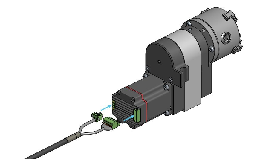
Plugging in connections on the closed loop motor
Please follow the instructions specific to your controller type.
AltMill has SLB-EXT.
LongMill has SLB, unless you have the Closed Loop Motor Kit upgrade, in which case you have the SLB-EXT.
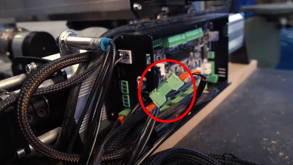
Plug in the power, limit switch and driver connectors into their appropriate locations as shown below.
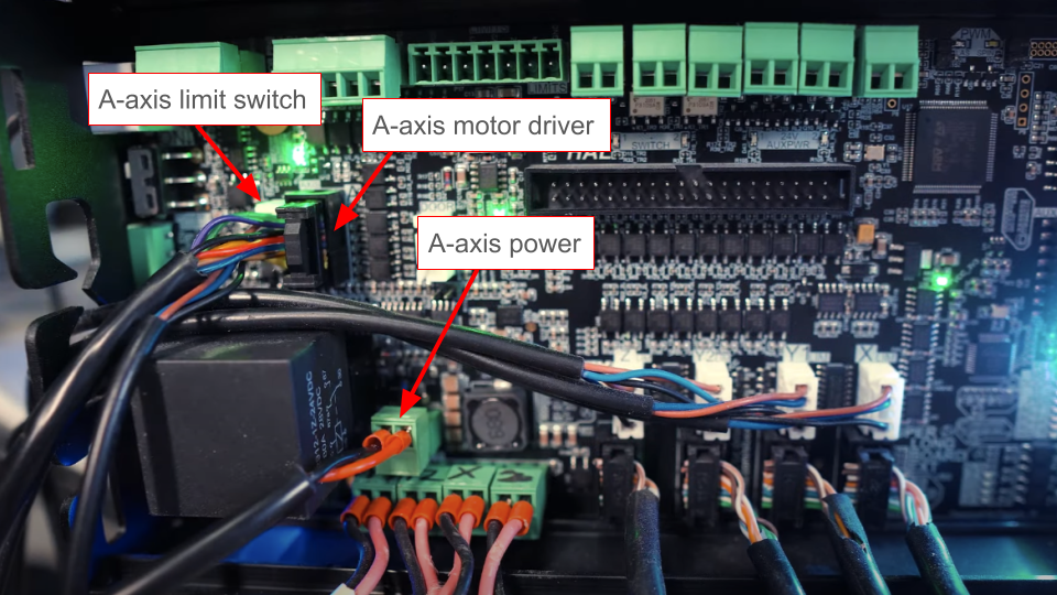
A-axis connections to the SLB-EXT (AltMill)
Make the motor driver and limit switch connections as shown.
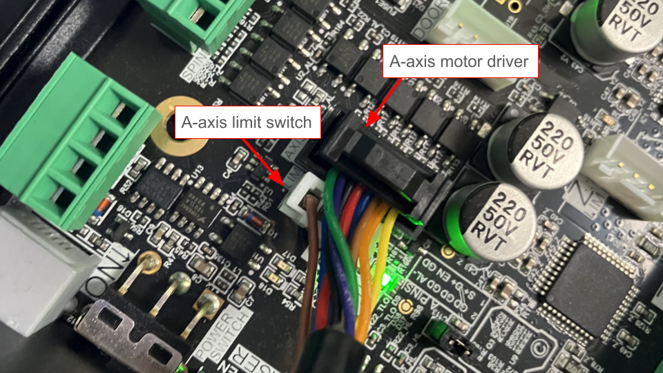
A-axis connections to the SLB (LongMill)
Plug the power splitter into the external power supply that comes with your controller.
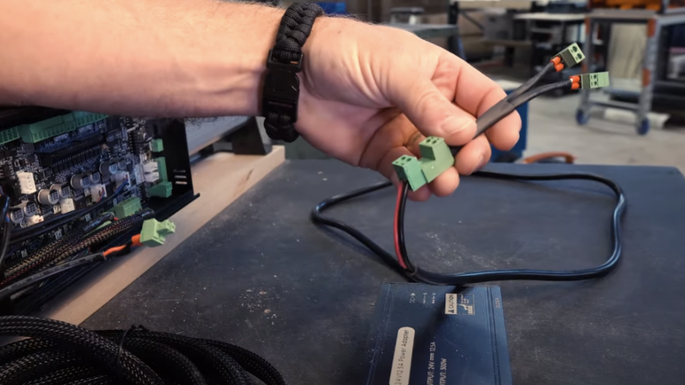
Power splitter for the SLB A-axis connections
The two green connectors will be distinctly different, so you can make the appropriate connections to power the controller and the A-axis.
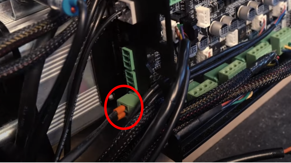
Connect power splitter to POWER input on the side of the SLB
Plug the other end of the splitter to Vortex power connector
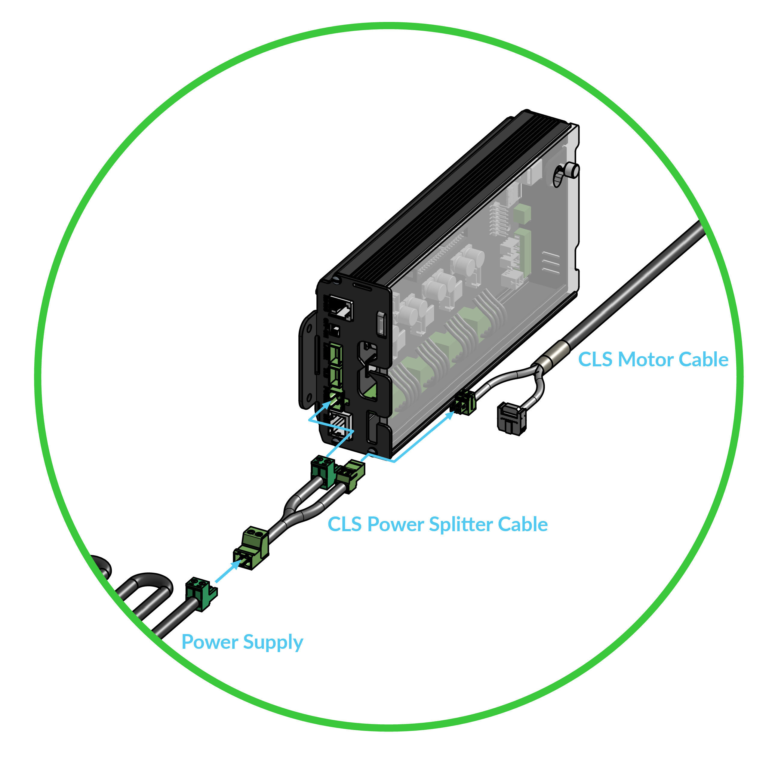
Power splitter wiring overview
Firmware Settings
Whether you have an AltMill or LongMill, you must change the firmware settings to use the closed loop Vortex.
gSender 1.5.0 and above
Next, we will need to change the firmware settings to work with closed loop rotary axis.
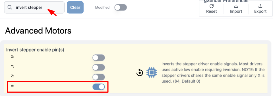
Go to Config, then use the search bar to find the following settings:
$4 Invert stepper enable pins → toggle A to be ON (do not adjust X, Y, Z settings)
$21 Hard limits enable → toggle Enable to be OFF 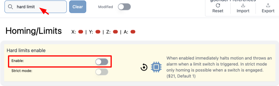
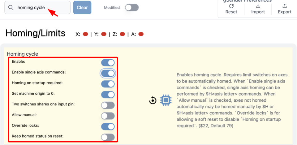
$22 Homing cycle → match the toggles as shown
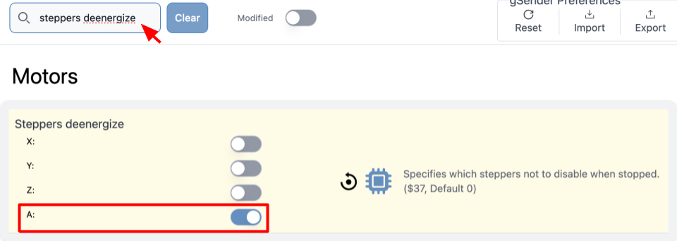
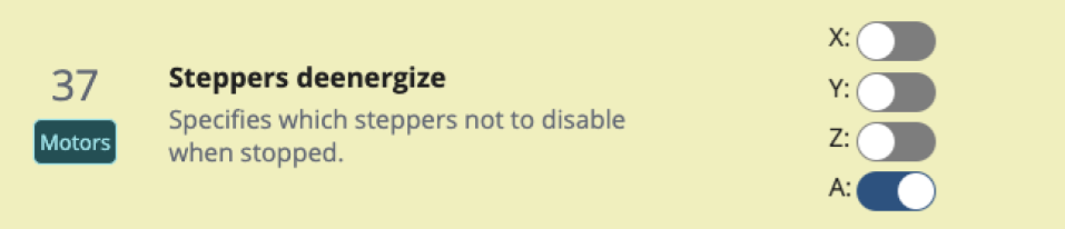
$37 Steppers deenergize → toggle A to be ON
Once you have made these changes, press ‘Apply Settings.’
Go back to the main ‘Carve’ page.
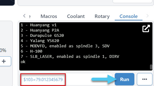
At the bottom right of the screen, select Console.
Type in $103 = 79.012345679 then press Run
Power OFF then ON the control board so that all the changes will take effect.
gSender 1.4.12 and below
Next, we will need to change the firmware settings to work with closed loop rotary axis.
On the Firmware Tool, make the following changes and press “Apply New Settings”:
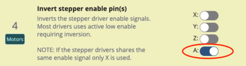
$4 – A toggle is ON, DO NOT TOUCH XYZ
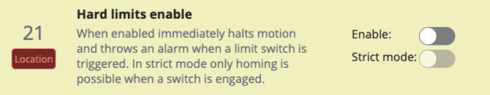
$21 – Enable is OFF
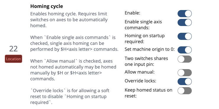
$22 – Enable ON, Enable single axis commands ON, Homing on startup required ON, Set machine origin to 0 ON, Override locks ON .
Ensure you enable the following setting. The closed-loop stepper motors need to be power to the motors before receiving a move command. If you are experiencing a delay when jogging the A-Axis, it’s likely A hasn’t been toggled on.
$37 – A toggle is ON.
LongMill customers with spindles are recommended to enable the Z axis for 37 Steppers deenergize. When using the spindle kit with the vortex the following settings are:
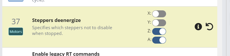
$37 – A & Z toggle is ON.
One the settings are saved, go to the Console on the main gSender window. Type in $103 = 79.012345679 then press “Run”
Manually enter setting $103 on the Console tab
Power OFF then ON the control board so that all the changes are updated in the Firmware Tool.
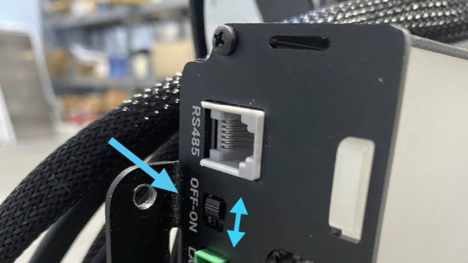
Switch OFF then ON on the SLB and SLB-EXT
Motor Check
Check the dip switches on the back of the closed-loop stepper motor to ensure they are set to the correct settings. Use a small tool to seat the small switches. The switches should be:
1 – ON, 2-ON, 3-ON, 4-OFF, 5-ON
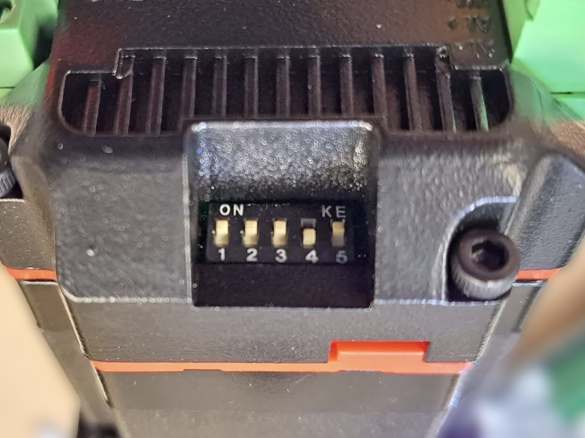
Vortex Closed-Loop Dip Switch Position
Congratulations! A job well done, you’ve completed the assembly and firmware steps. Take a deep breath, we are almost ready for a test drive.