Using gSender
Starting Up
When you double click the gSender icon to open up the program, it can take several extra seconds to load if you have Microsoft real time virus protection on your computer. This scan delay should only happen the first time you turn on your computer.
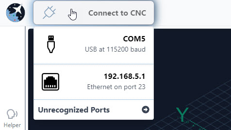
Connect to your CNC machine by hovering over the Connect to CNC button at the top left corner of the screen and clicking the first option (note that it’s recommended to connect this way on your first setup even if you’re planning to use Ethernet in the long-run).
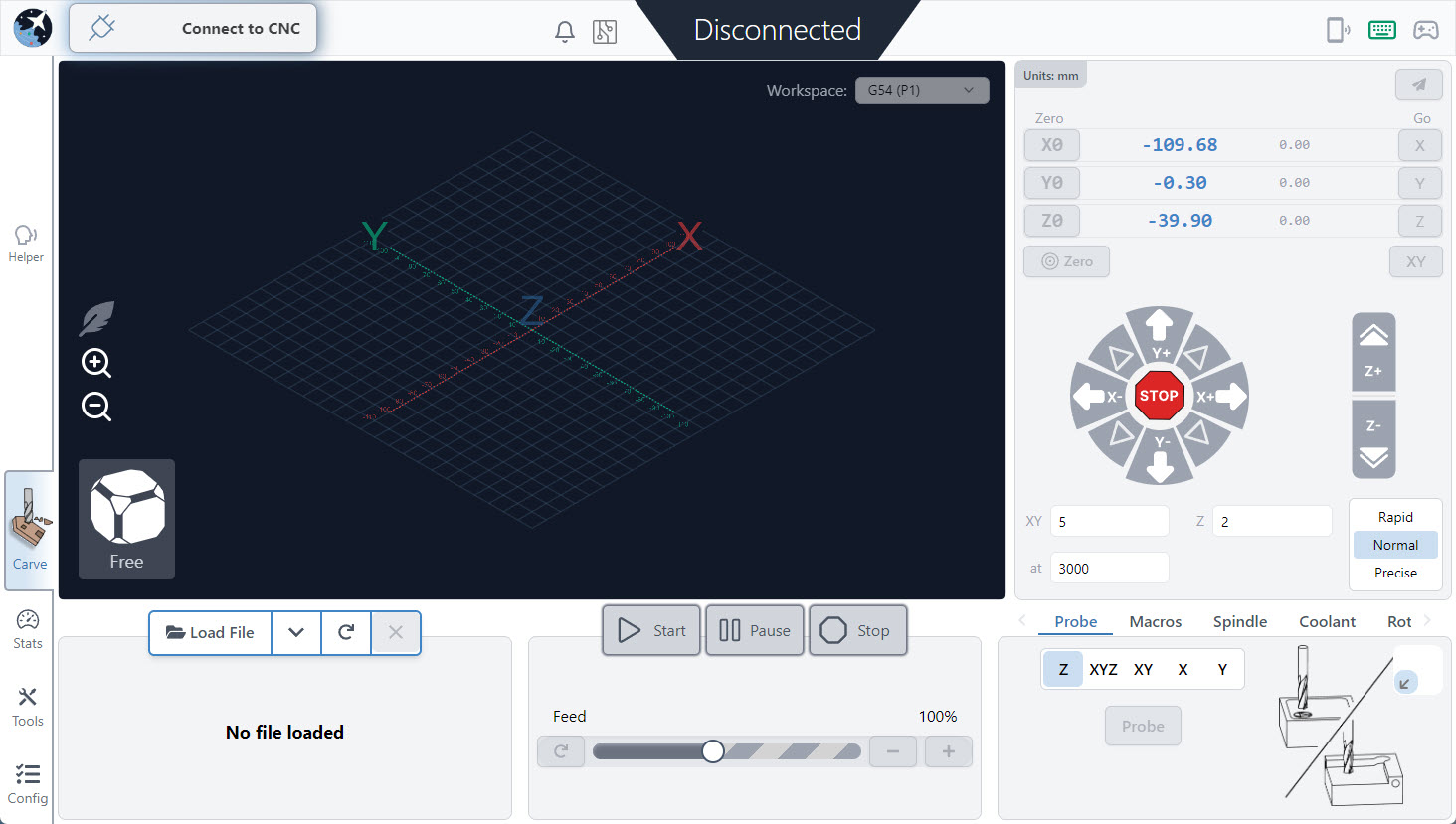
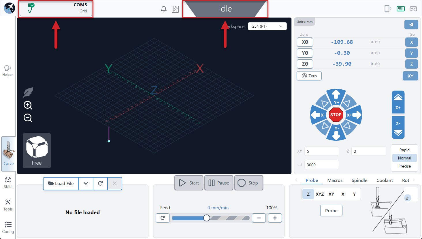
After a moment you should see the plug icon turn green with a checkmark, the status bar at the top, middle change from Disconnected to Idle, and all the controls in the app become coloured indicating that they’re ready to be used.
If you don’t see all these changes happen, we’d recommend you check a couple things then retry:
- You have a secure connection between your machine’s control board and computer.
- Click the ‘Connect’ button again to Disconnect, then hover over it to check if there are any other options listed that you can try. For some CNCs you might have to check the ‘Unrecognized Ports’ dropdown then help us update our list of recognized CNCs.
- Ensure that any other programs that could be talking to your CNC are closed (ex. Easel, UGS, Arduino IDE).
- Update gSender’s Baud Rate in Config ➜ Basics since your board might not use the typical 115200. Check the specs with your manufacturer.
- Arduino is securely attached to the LongBoard. (Not applicable for the SLB)
- If it’s connecting but behaving oddly, gSender’s automatic firmware detection might’ve failed. In this case ensure you set your board’s correct firmware as grbl or grblHAL under Config ➜ Basics ➜ Firmware fallback.
Ethernet Connection
An Ethernet setup is a bit more involved than using USB, but if you’re looking to switch over due to its inherent reliabilities that will always make it more robust, you’ll need to make sure you have an Ethernet cable on hand and that your device has a free Ethernet port. You’ll also want to double-check since some Ethernet-driven CNC control boards like the SLB aren’t able to be firmware flashed over Ethernet, so you’ll still need to keep a USB cable handy if you need to do any future updates or recover from a board reset.
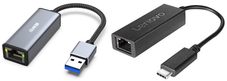
- If your computer only has one Ethernet port and it’s already used, you can try picking up a USB to Ethernet dongle or adding an additional Ethernet card. If you use the dongle, the USB side will plug into your computer, and the Ethernet side will connect an Ethernet cable that you’ll run to your board.
Ethernet on Windows
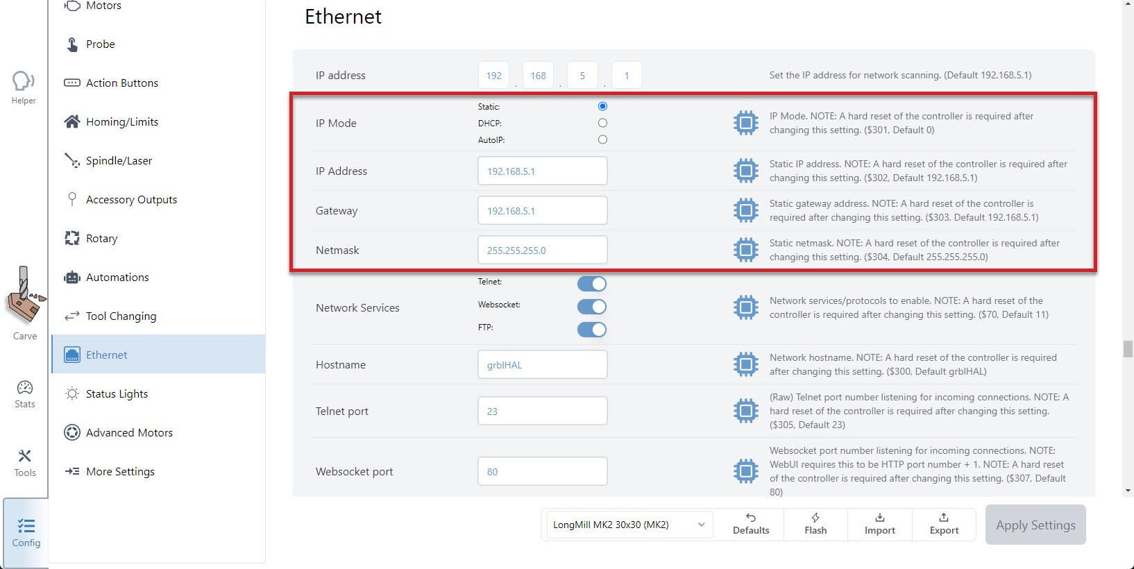
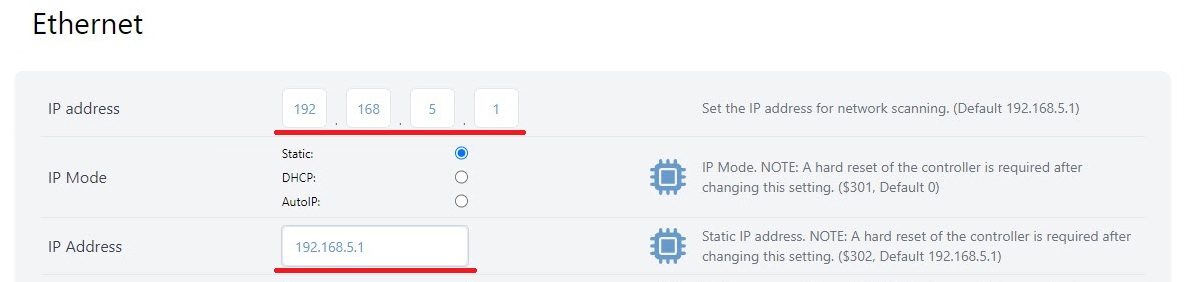
- To start, connect to your CNC over USB, open the Config tab to the Ethernet section, and copy down the numbers you see for the ‘IP address‘ and ‘Netmask‘. The defaults should be
192.168.5.1and255.255.255.0respectively, with the IP mode set tostatic.
- Once copied down, you can unplug your USB and connect the Ethernet cable directly from your PC to your board. If you look where you plugged the Ethernet cable into the board from the outside, you should see a green light on and a flickering yellow light.
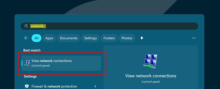
- Now you’ll need to configure the PC’s Ethernet interface. Start by opening the Windows menu, searching for “network” and click ‘View network connections‘ to get a list of Ethernet ports.
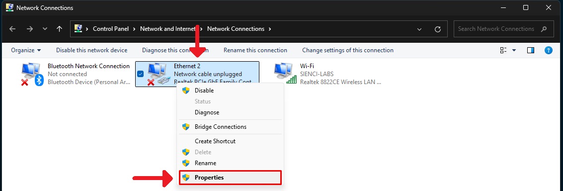
- Here you should be able to find the ‘Ethernet‘ listed that you just connected to your board. Even if there are multiple Ethernet options, unplugging and re-plugging the cable from the board will show which one it is. Once you know, right-click it and open its ‘Properties‘.
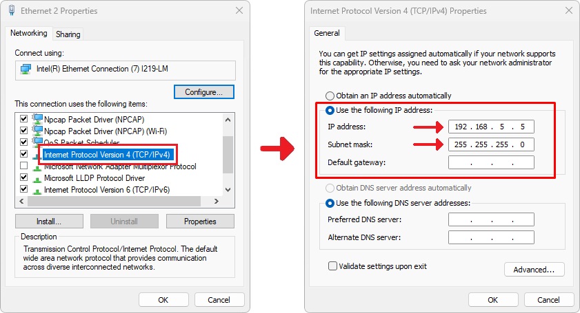
- In the Properties, find the option for ‘Internet Protocol Version 4 (TCP/IPv4)‘ and double-click it. Here, you’ll want to:
- Select the ‘Use the following IP address‘ option
- Type into ‘Subnet mask‘ the ‘Netmask’ number you copied down
- Type in the ‘IP address‘ that you copied down, just change the last number (for example, change it from
192.168.5.1to192.168.5.5) - Click ‘OK‘ to save and close the options
- Back in gSenders Config tab ➜ Ethernet section, make sure the IP address for gSender matches the IP address from the firmware.
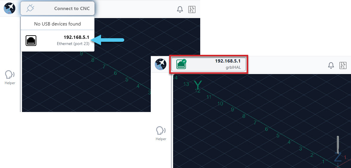
- Now click on Connect to CNC, choose the Ethernet Port option and you should see it connect successfully 🙂
- If you have a problem connecting with Ethernet, go back over the setup steps. You can also reconnect over USB to double-check your boards Ethernet settings.
Ethernet on Mac
To set up an Ethernet connection from a Mac, you’ll follow a lot of the same steps as for Ethernet on Windows but after doing Step 2:
- On your Mac, click the Apple menu ➜ System Settings ➜ then click ‘🌐 Network’ in the sidebar (you may need to scroll down).
- Click Ethernet service ➜ ‘Details…’. Note: if your Mac doesn’t have a built-in Ethernet port and you’re using an adapter, look for a service that contains the name of the adapter manufacturer or the type of adapter. For example, the service might be named [manufacturer name] USB-C LAN, or just contain the model number of the adapter.
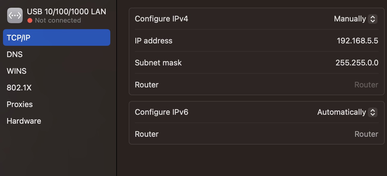
- Click TCP/IP in the sidebar ➜ then for ‘Configure IPv4’ choose ‘Manually’ so you can enter the specific IP address and subnet mask. You want the subnet mask to be the same value from the EEPROM ‘Netmask’. The IP address should have a different last digit on the same mask – so if the board is device 1 (192.168.5.1), you could call your PC device 5 (192.168.5.5). Click “OK” to save and close the options.
- Resume following the Windows instructions at Step 6 to finish the process.
Jogging and Presets
You can move the machine manually by using the Jog Control, through the arrow buttons. To move the Z axis up and down, use the Z+ or Z- buttons to the right of the control dial.
Below the control dial, you can change the XY value and Z value to adjust the distance you travel per click. You can also change Speed, which determines how fast the machine will move when jogging. That value is reflected in the ‘at’ box.
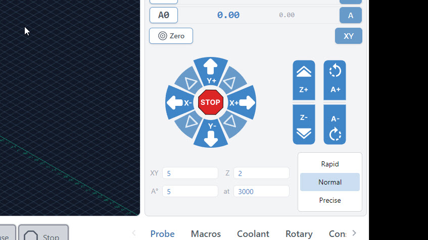
The Rapid, Normal, and Precise buttons are preset values that will allow you to toggle to different distance and speed values quickly. We use rapid to get around quickly on large jobs, and precise if we are trying to set zero with the paper method for example.
Set Zero and Go tos
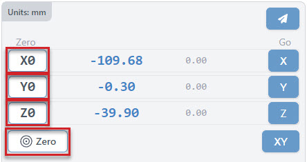
Each g-code file or project will have a starting position that all other movements are referenced off of. This is called the Workpiece zero. There are two ways to manually set your zero on gSender, and a couple automatic options that we cover in Probing:
- Zero each axis one at a time using ‘X0’, ‘Y0’, and ‘Z0’ buttons
- Set them all at the same time with the larger Zero button
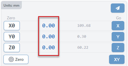
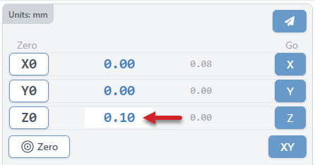
The large blue numbers tell you the current position of your machine. Once you set the zero of each axis, they will all read 0.00.
You can reset your zeros anytime when the machine is not actively running a job. The machine will remember your zero in most cases unless you forcibly move it by hand, but even then CNCs with homing can re-home and still return to the zero point.
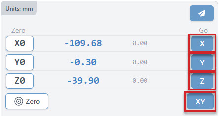
Now that we’ve covered how to manually move, here are two ways to automatically move, or as we call it, Go to:
- Return to each axis Zero, one at a time using the blue ‘X’, ‘Y’, and ‘Z’ buttons
- Return to X and Y Zero at the same time with the blue ‘XY’ button
Note – ‘Go to XY’ will not move the z-axis to its zero.
Note: if you’ve set up “Safe Height” in gSender (Config ➜ Basics ➜ Safe Height), then the Z-axis will move up by that distance before moving the X or Y to make sure your machine doesn’t run into clamps or other materials.
There is one more way to move automatically, but it isn’t used to bring you back to 0.00. It’s called Go to Location.
If you want to go somewhere quickly without manually jogging there, click the ‘Paper Airplane’ button and you’ll see a popup asking you where you want to go. Before you click “Go!” you can either:
- Set the toggle to “ABS” then type a specific location you want to go, for example X100 Y150 (an absolute/fixed location)
- Set the toggle to “INC” then type the amount you want to move from where your CNC currently is, for example 5 in X and 10 in Y (an incremental/relative movement)
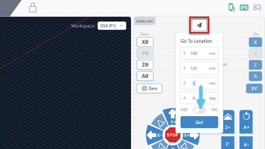
You can also enter coordinates directly by clicking the blue text. It’ll turn into a white box where you can type any number, then hit the ‘enter’ key to confirm it. For instance you could set your Z-axis to 0.1mm instead of 0 if you’re using the paper method and you want to account for the paper thickness. You could also type “-10” for X if you want to set your zero 10mm to the right without having to jog there and click ‘X0’ (since if ‘zero’ is 10mm to the right, then your current location would be 0 – 10 = -10mm).
Homing buttons
gSender provides unique features if your machine is capable of homing using limit switches. Once homing is enabled in Config ➜ Homing cycle you’ll notice additional buttons appear in the ‘Location’ area of gSender:
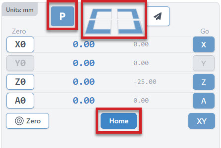
- The Home button is a convenient way to home or re-home your machine at any time.
- Four Quick-Travel buttons help move your CNC at its maximum speed to any of your machine’s 4 corners (offset by 5mm). These can only be used once your machine is homed.
- The Park button will allow you to move your machine to a custom location set in Config ➜ Homing/Limits.
If you’d like more information on how to set up and use these features, read here: Installing & Using Limit Switches
Note – If you’ve set up a “Safe Height” in your gSender settings, now any “go to” or “quick-travel” button will move to the top of the Z-axis minus the safe height before moving anywhere to make sure your machine doesn’t run into clamps or other materials.
Probing
Probing automatically sets a zero position, usually at the bottom left corner of the stock material, using a touch plate. If you’re not using a Sienci touch plate, read here to make sure your settings are set up correctly.
You can select the type of touch plate you are using in the Config ➜ Probe section. You can see the standard touch plate allows you to enter values (block thickness and probe speeds), while the AutoZero touch plate automatically fills these values in for you. This section also toggles the probe connection test on and off.
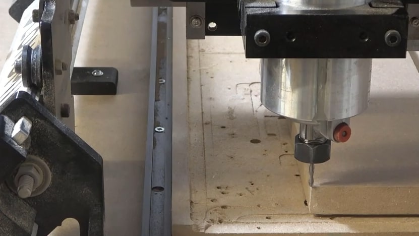
Once you have set up the touch plate, banana plug and magnet on the machine, you can choose which axis to probe for (default is bottom left corner), and the diameter of the bit you are using if applicable. The bit size can be selected from the drop-down of saved bits, or can be typed in manually. Custom diameters will be saved for future use if you hit the + symbol after entering your diameter. You will see two extra options if using the AutoZero touch plate, Auto (automatically finds diameter) and Tip (used for V-bits). Jog the machine so that the bit is hovering over the Sienci Labs logo on the touch plate. Then press ‘Probe’.
Before the process begins, there is a conductivity test to ensure that the touch plate components can conduct electricity, which allows a signal to be sent to the LongBoard when there is contact. You can either bring the touch plate to the end mill or touch the banana plug and magnet together. Make contact a few times just to confirm there is conductivity, as the red circle should flicker to green.
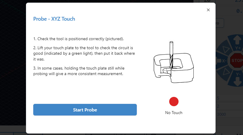
A blue button called ‘Start Probe’ will appear if you have successfully confirmed conductivity. Ensure that the touch plate components are set up for probing, then press ‘Start Probe’. The machine will move to probe three sides of the touch plate, twice on each side. There should not be any crashing or abrupt movement. Once the process is over, remove the touch plate components from the machine and then press ‘Go to XY’. The bit should be overtop the bottom left corner of the stock material, and pressing ‘Go to Z’ should bring it to touch the surface. More information can be found on our touch-plate resource page. https://resources.sienci.com/view/lmk2-touch-plate/
If you have a different setup where probing the front, left corner is less convenient for you, gSender can also probe other corners by clicking the corner button. You’ll see the blue arrow point to the corner you want to probe from, then you can follow the rest of the probing process the same way.
For two-sided cutting, this can also allow you to register off the same corner on both sides so your tool paths line up (for example, the front left would become the back left when you flip it over).
Loading Job Files
If you have already prepared a project file, ensure the following:
- The file is an *.nc, *.g-code, *.tap, *.gc, or *.cnc file.
- The file is exported to the correct post processor for the LongMill. Please see this page for the correct post processor for your CAM software: https://resources.sienci.com/view/lm-post-processors/.
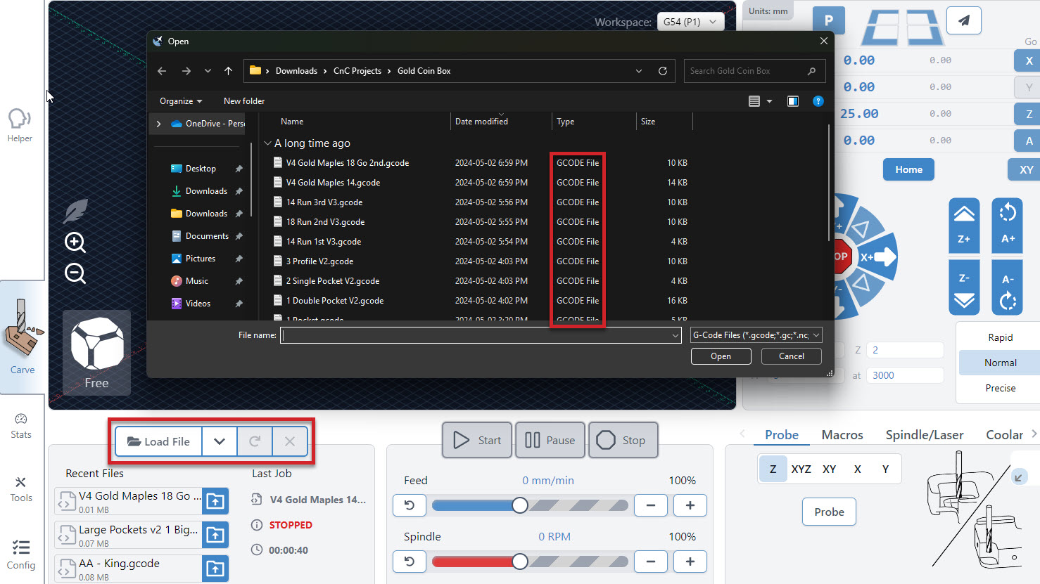
To run your project on gSender, press the ‘Load File’ button. A dialog box will pop up, where you can navigate to where your file is. Here you can also select from recently loaded files, reload a file, or close a file.
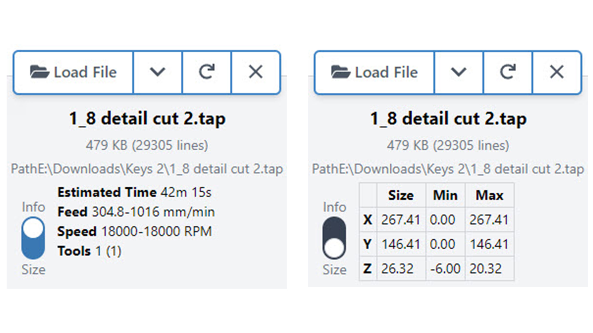
Once loaded, you’ll be able to toggle between Info and Size to reveal stats about your project such as: Estimated cut time, Feed rate, Spindle Speed, Cutting dimensions, Min/Max values and more.
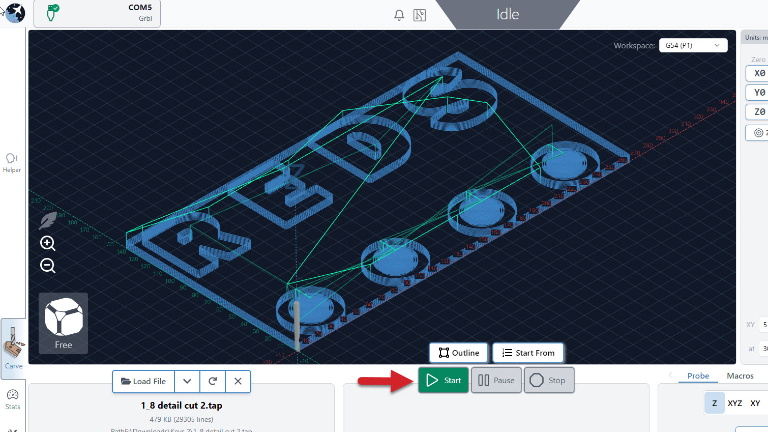
Loaded files are shown on the Visualizer so you can check out how it looks. Click the different sides of the ‘view cube’ in the bottom left corner to quickly switch between different views like: top, front, left, right, and 3D. You can also left-click and drag or right-click and drag to rotate or slide around the work area, or use your mouse scroll wheel to zoom in and out.
Before running your job there’s another handy feature you can check. The Outline button will physically move your machine around the rough perimeter of your cutting job so you can get an idea of the cutting dimensions and if you’ve positioned the job correctly.

Running Jobs
Once your machine is ready with your router and vacuum on, press Start to begin your cut. You can pause and stop your job at any time with the respective buttons. If you press Pause, you can resume the job from where you left off. Otherwise, Stop will cancel your job completely.
Hitting the pause button will pause the movement immediately, even if gSender has plans to move in the buffer (memory). If you are using a macro or Program Events like program pause, this will pause movement more slowly, as the planned moves in the buffer will finish before actually pausing. This is something that can’t be avoided on the firmware side and this is a compromise to be able to execute code at all.
In the default visualizer you’ll see that cutting movements that plan to be made are coloured blue, then when the job is running the current movements show as yellow and past movements are grey.
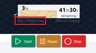
At the bottom of the visualizer, an animated progress bar shows you several details about the job you are running, like completion %, estimated time remaining, g-code line counter, and a running timer for how long you have been cutting.
Additionally, you can override the feed rate and spindle speed of the program while the job is running if you’re finding the speeds you set in your file were too slow/fast. Do this by moving then letting go of the slider, pressing the ‘+’ and ‘-‘ buttons for smaller adjustment, or clicking the rotated arrow to reset back to the default value. You can also do this before starting the job if you already know you’ll need to make tweaks.
Now you’re off and cutting, what a thrill! While your job is running keep an eye and ear out for anything you don’t expect. You can always use the job control buttons during operation to change speeds, pause, resume, or stop cutting altogether.
Job Loss Recovery
Also called “Start from Line”, this feature can recover a carve you were working on that:
- You had to manually stop part-way through
- Was disrupted by a power loss, USB disconnect, mechanical malfunction, or other failure so you need to resume from where it failed
- Was really long, so you want to resume carving after pausing it for the night
- You only wanted to run part of the job anyway
It does this by looking through the whole g-code file up to where you want to resume running to see all the movements up to that point, what accessories were turned on, the power of a spindle or laser, and runs any automatic commands you’ve set up in gSender. This way you can be confident in returning to your projects, even when something has gone awry.
Steps to Resume Cutting
- Make sure to have the g-code file loaded that got interrupted (or that you want to start carving part-way through).
- If you think your machine lost its location:
- Re-home the machine (it should remember the zero location of the project if nothing else moved).
- If you don’t have limit switches, the project moved, or your original cutting bit broke, try to re-use whatever setup method you used to set your zero location originally. This could be with a touch plate, 3D probe, paper method – whatever possible to set the project back up the way it was before it failed.
- Once everything looks set up correctly, you should be able to ‘Go to’ the original zero position and see that the bit is lined up correctly to the material. The location should read all zeros for each axis.
- Raise up the Z-axis a couple millimeters for safety.
- Click the small icon at the top right of the green ‘Start Job’ button to open the window.
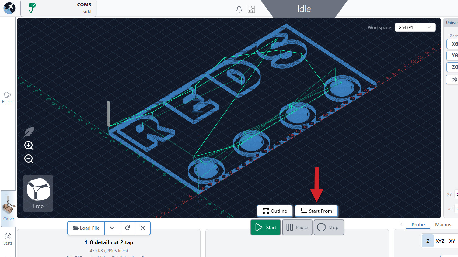
- Here you’ll see:
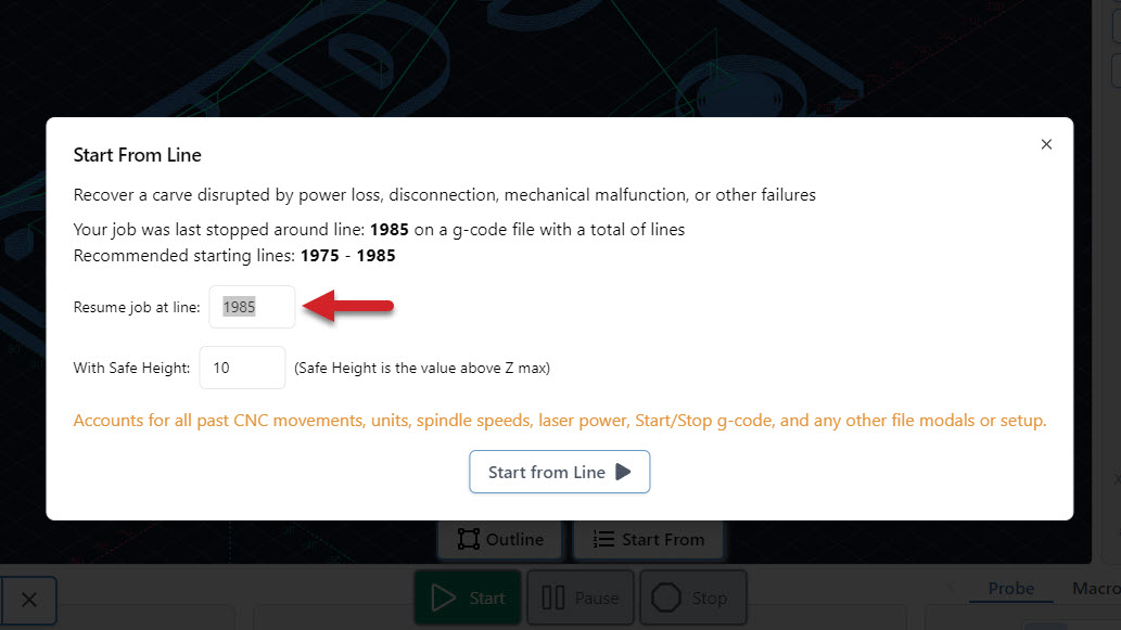
- When you Last stopped your file, how many Total lines it has, and a Recommended start line.
- Resume job at line: once you’ve decided where to resume from, you can type the line number in here.
- Safe height: if your CNC has extra Z movement above the failed job, you can put a larger number here to make sure that it doesn’t hit clamps while moving into position to resume cutting.
- Once everything looks good, remember to turn on anything that isn’t automated like a trim router or vacuum, then click ‘Start from Line’ to resume cutting.
Example: you were present when the job failed and hit ‘Stop’ immediately. Nothing moved but the bit broke so you swapped it out and used a touch plate to probe Z. It says the last recorded line was 731 but to be safe you’ll subtract 20 and start at 711. The job starts back up a little before the failure and you’re able to resume as expected. If instead you hadn’t been paying attention for several minutes then you might subtract 50-100 lines instead just to be safe.

Pause Cutting Mid-Job
- If a carve is dragging on and you need to leave the machine for the night, first you’ll want to note down the approximate g-code line number it’s at. In the example below you’d note down “803 lines”.
- Once noted down, ‘Pause’, then ‘Stop’ the job. This allows the machine to stop more slowly instead of emergency stop.
- Quickly turn off anything that isn’t automated like a router or dust collector and jog the Z-axis up so you don’t burn or mar the material. You can also try to pause strategically when the bit is moving and not cutting to avoid damaging your material.
- At this point it’s best to return the cutting tool to the project zero point if possible using the blue ‘XY’ button then the blue ‘Z’ button for the Z-axis. This will Go to your original zero. This way if the zero point is lost when you resume cutting later, then you can just manually set your zero knowing you’re still at the zero location.
- If you’re concerned your machine might drift over time for example if you’re using a heavy spindle, then another option is to place a block of wood under your cutting tool and jog down to it using the paper method. Once the bit is touching, you can note down the location where you left the machine, then when you resume you can type that location back in (see the end of Set Zero and Go tos).
Safety
gSender is set up to do many things by default to help keep you aware about things going on with your machine. Though we can’t guarantee it can handle everything, you can access many safety items in one place. This includes:
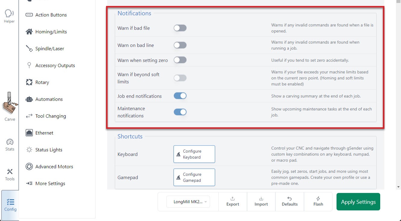
- G-code warnings: reports back when it sees g-code lines that don’t look correct when the file is loaded or once it’s being sent to the machine. G-code has to follow specific ‘grammatical rules’ similar to other languages for the ‘sentences’ to be correct, so if the lines don’t look correct then your machine might run into problems understanding what it’s supposed to do.
- Soft limits warning: enables gSender to tell you when a loaded file might exceed the cutting area of your machine. This requires that your machine has limit switches and soft limits enabled.
- Prompt when setting zero: enable an optional popup that appears when you click to ‘zero’ just in case you mis-clicked it.
- Safe height movement: this number is used when using the ‘Go to’ buttons in gSender to manually move your machine around (it’s independent from a safe height you might set in your CAM software). For machines without homing, entering ‘5mm’ will make it move 5mm upwards from the current position, make the Go to movement, then move 5mm back down. If your machine has homing, it’ll move to 5mm from the max Z-axis travel, make the Go to movement, and then return back to where the bit started. This behaviour helps homing-capable machines to reach a more ideal safe height to avoid collisions during movements.
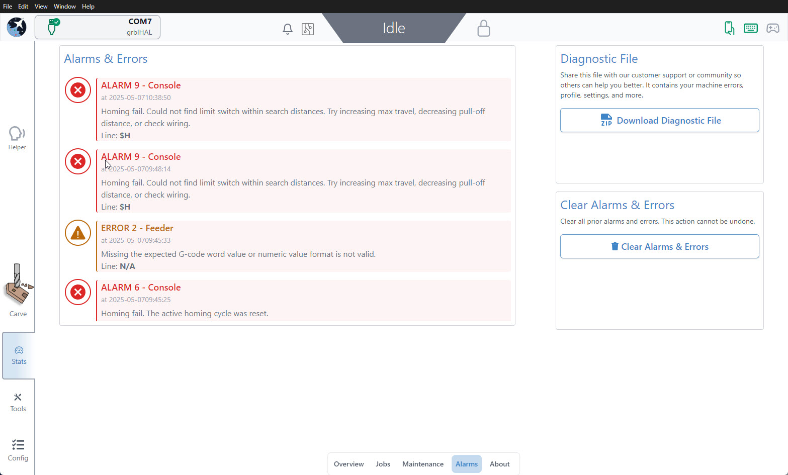
- History of Errors and Alarms: great for tracking problems you might’ve recently run into to help troubleshooting or getting support. All entries are listed in-order and stamped with a date and time.