
All Sienci Labs machines are compatible with the AutoZero Touch Plate.
Before we begin setup, please download the latest version of gSender.
Setup
Step 1: Unboxing
Each order for the AutoZero Touch Plate comes with:
- The touch plate itself
- A cable with a 2-pronged green connector on one end, and a magnet and banana plug on the other end
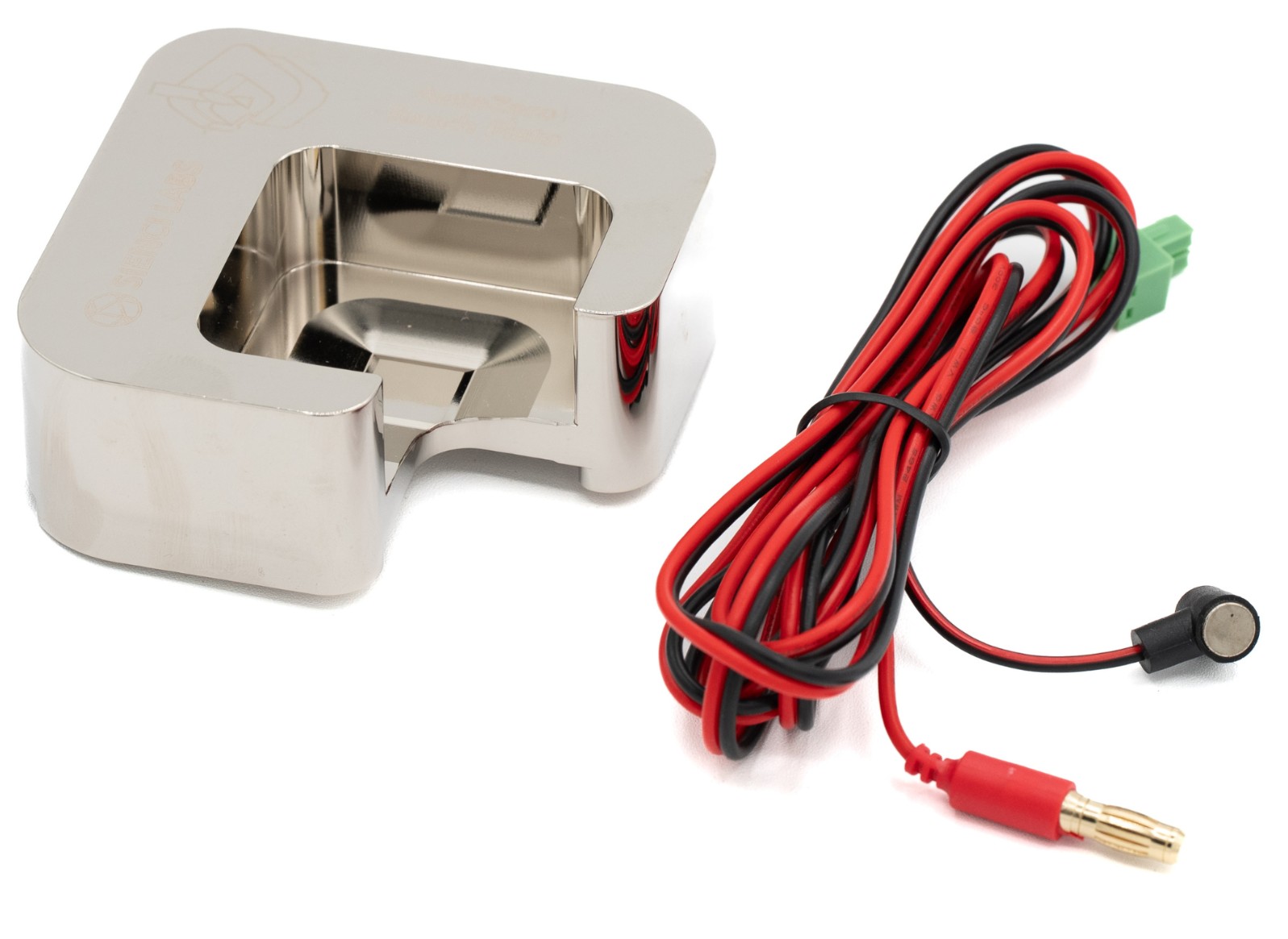
If your cable didn’t come with the green connector, you can use the spare that’s plugged into your controller already. Attach the connector to the wire leads using a flat head screwdriver. The polarity of the wires does not matter.
Step 2: Update your gSender settings
-
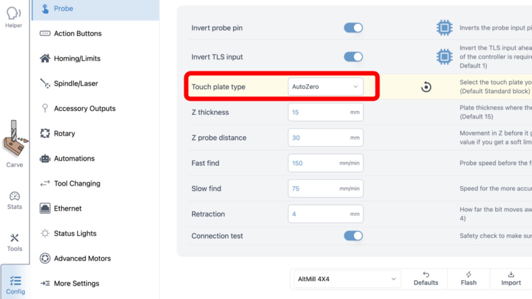
On gSender, go to Config ➜ Probe ➜ Touch plate type: AutoZero
-
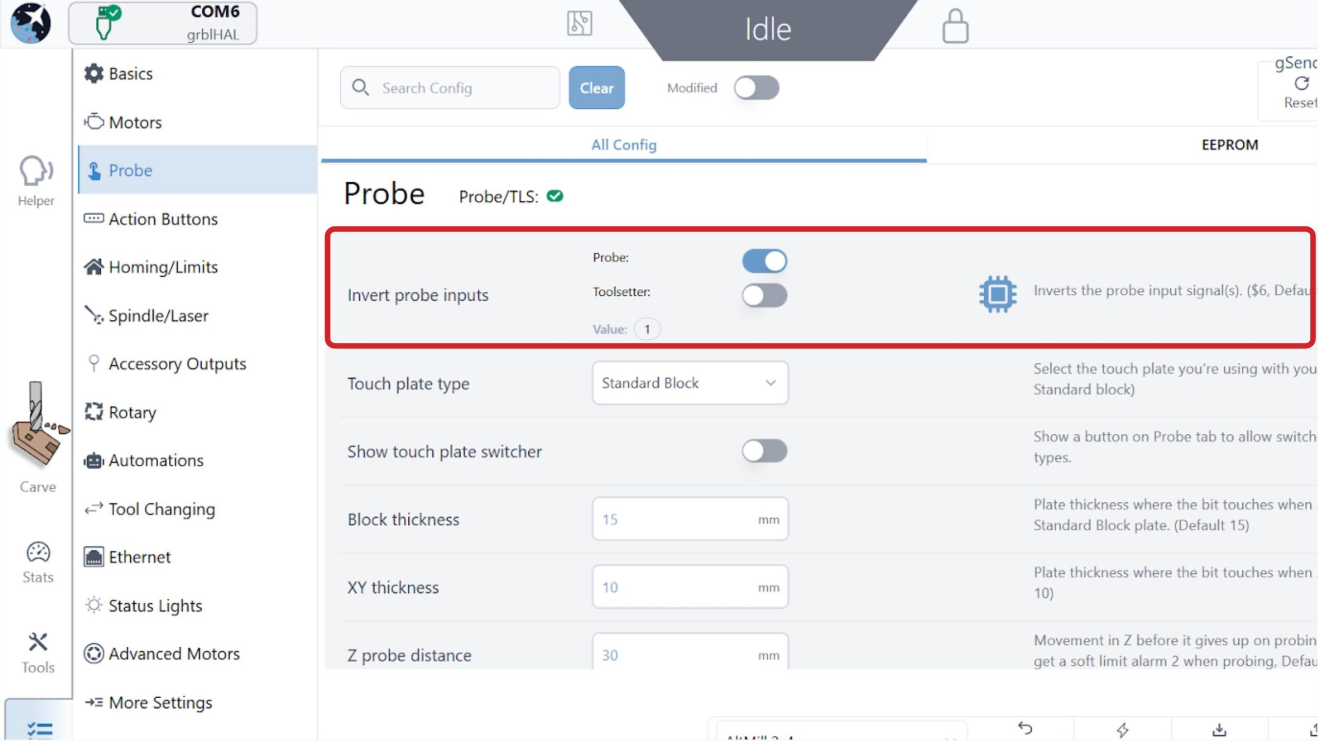
In the Invert probe inputs, toggle ON the Probe. If you have a Sienci Labs TLS, please toggle OFF the Toolsetter too.
-
Press ‘Apply Settings’ at the bottom right of the screen to confirm this change.
-
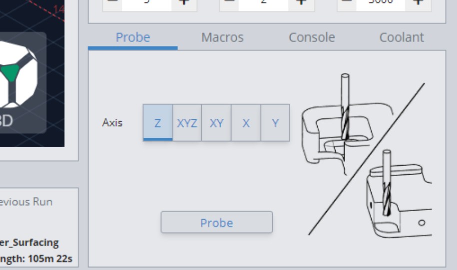
Go back to the main ‘Carve’ screen.
-
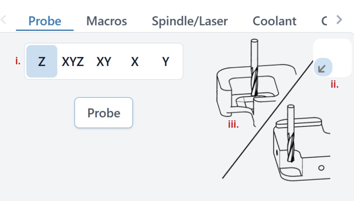
The ‘Probe’ tab at the bottom right of the screen should now be updated. Notice the following features:
i. You can select which axis to probe in
ii. You can select which corner you want to probe your material at.
- Default is front left corner of your material
- This setting changes the direction of the probing process
iii. The images show how to position your cutting tool to perform probing for the specific axis
-
On gSender, go to settings (gear icon at the top, right of the window) ➜ go to the ‘Probe’ settings ➜ and change the touch plate type to AutoZero Touch plate in the dropdown menu.
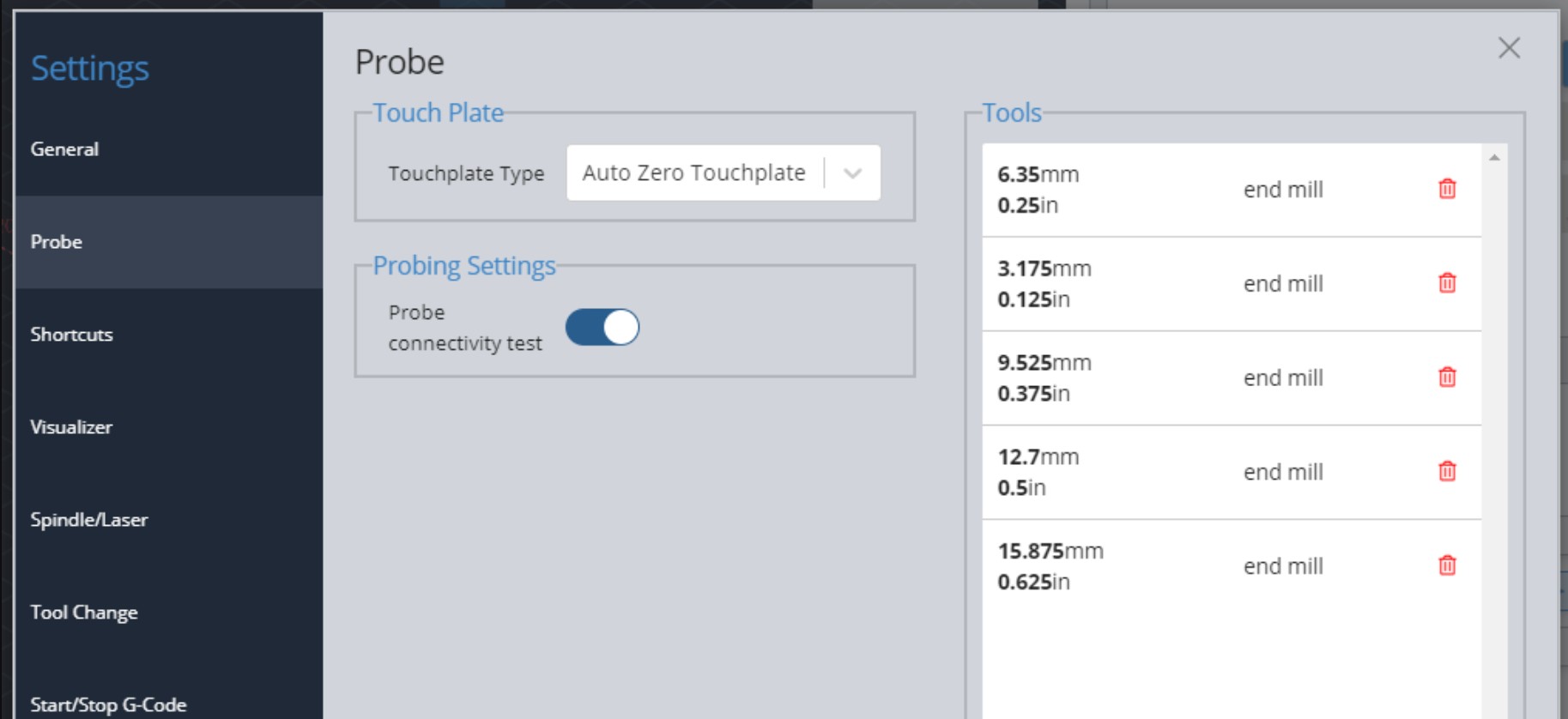
-
We recommend leaving the “Probe Connectivity Test” option activated as well. If you’re not using gSender, we also provide macros for other common senders.
-
Your ‘Probe’ tab at the bottom right side of the main screen should now show images of the AutoZero, indicating where to position your bit to conduct probing for that axis.
Step 3: Setting up the touch plate on your workpiece
-
Start off by plugging the green connector into the PROBE port on the controller.
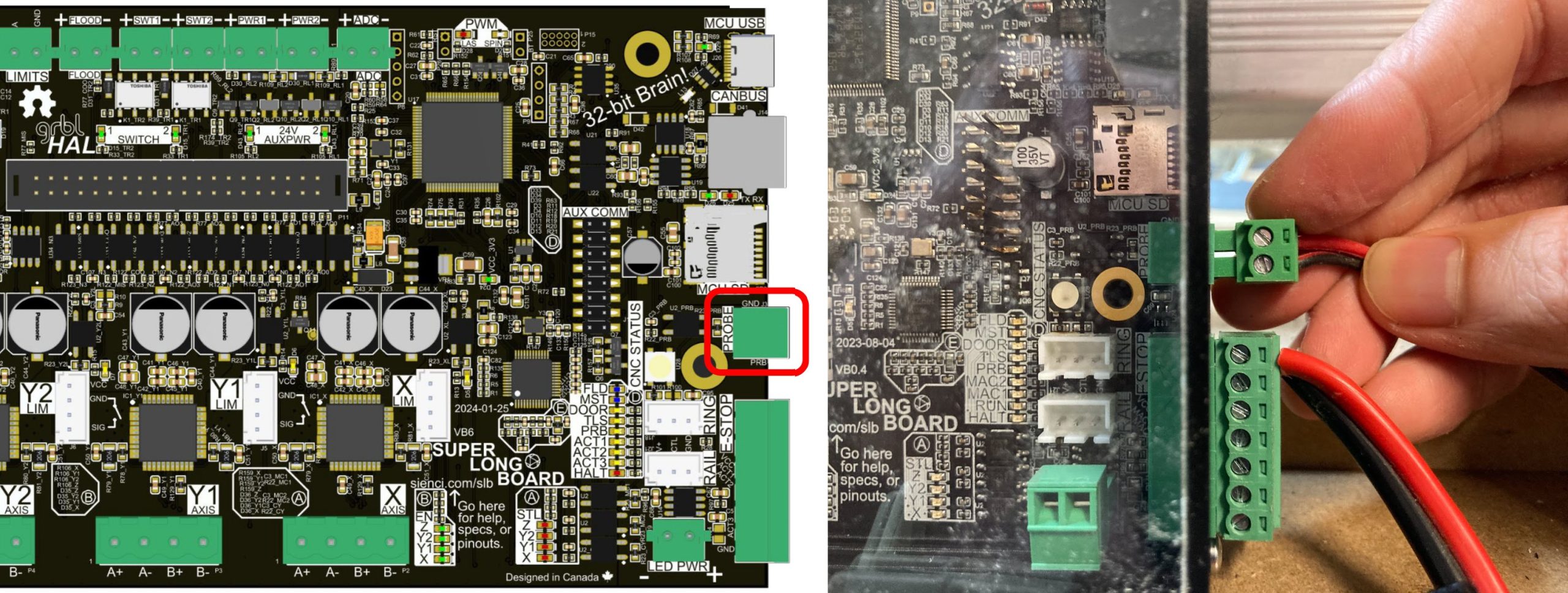
-
Plug the banana plug into the touch plate. There are two holes on the plate, either of which can be used.
The AutoZero touch plate is designed to set the X, Y, and Z zeros on flat, rectangular pieces of material. If you flip the touch plate, it can also set the Z zero on most flat, irregularly-shaped materials. -
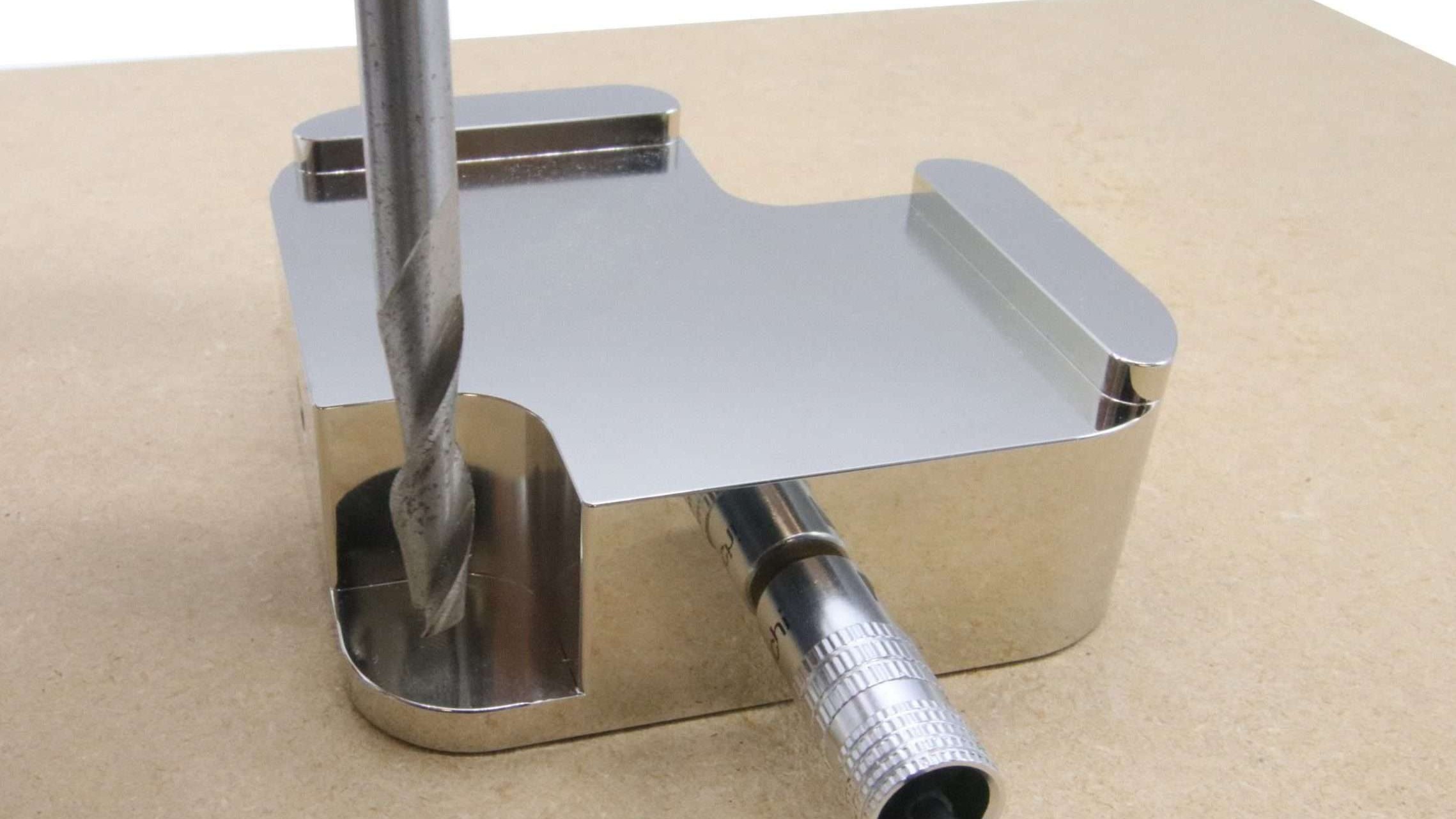
For probing in X, Y axes, put the block at the bottom left corner of your material. The inside edges should be touching against the sides of the material.
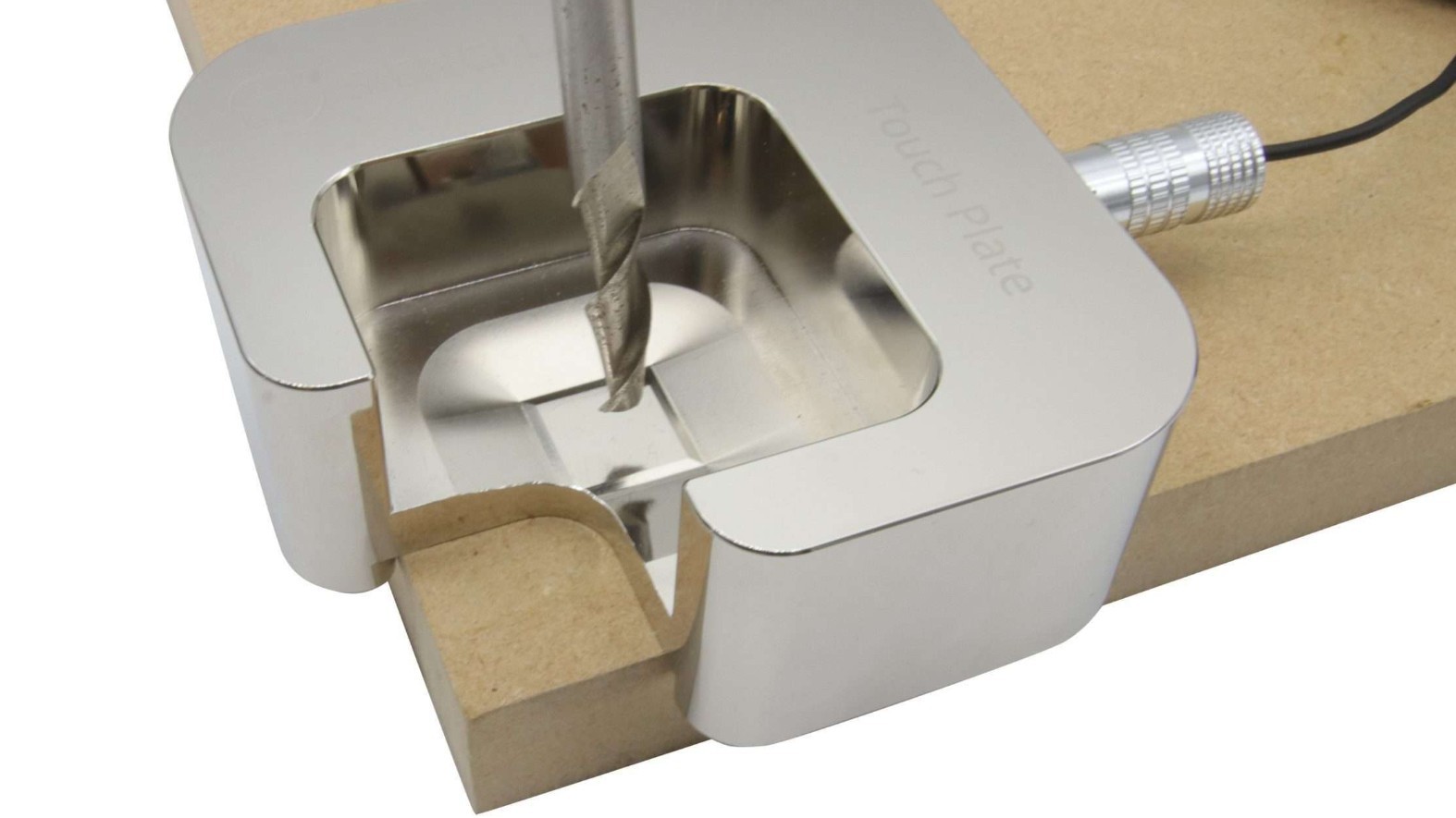
If you are probing just the Z-axis, you can still place the probe on the corner of the material. Or you could flip it over and place it on the surface of the material; probing will happen on this back lip.
Step 4: Probing
-
Attach the magnet to the router/spindle at the collet nut.
-
On gSender select the axis you wish to probe in.
-
In the dropdown you may see the options “Auto” or “Tip”, along with tool diameters. We recommend using Auto or Tip so that the machine can automatically detect the diameter. Make your selection based on your tool type:
-
Auto is used for straight end mills
-
Tip is used for v-bits, tapered, round groove and ball nose bits
-
-
Jog the tool over the touch plate to get it in the right position for probing.
For any probing type, jog the tool over the inner square.
For the Z probing, you could optionally jog the tool above the back lip of the flipped touch plate.
-
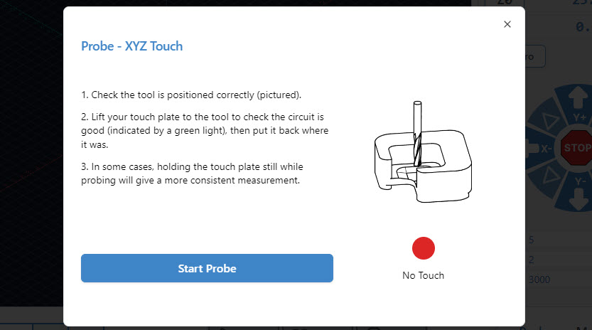
Press “Probe”.
gSender will prompt you to check for continuity before starting the process, to ensure your probe has the proper connection. Move the touch plate up to the tool to contact.
Finally, once the circuit has been confirmed, press Start Probe.
-
During the probing process, keep a hand against the plate to prevent it from sliding around. But also, stay alert to make sure your hand isn’t in the way of the tool.
Step 5: Remove magnet
Once your probing is complete, remove the magnet and move the touch plate out of the way. Your machine coordinates should now be updated and ready to use.
We hope you have an excellent experience with the AutoZero touch plate!
If you are running into any issues, make sure to check this video out below, as well as see our Troubleshooting section further down on this page.
Troubleshooting
Probing failed?
Here are some items to check:
-
Make sure you have AutoZero selected in the touch plate type setting in Config
-
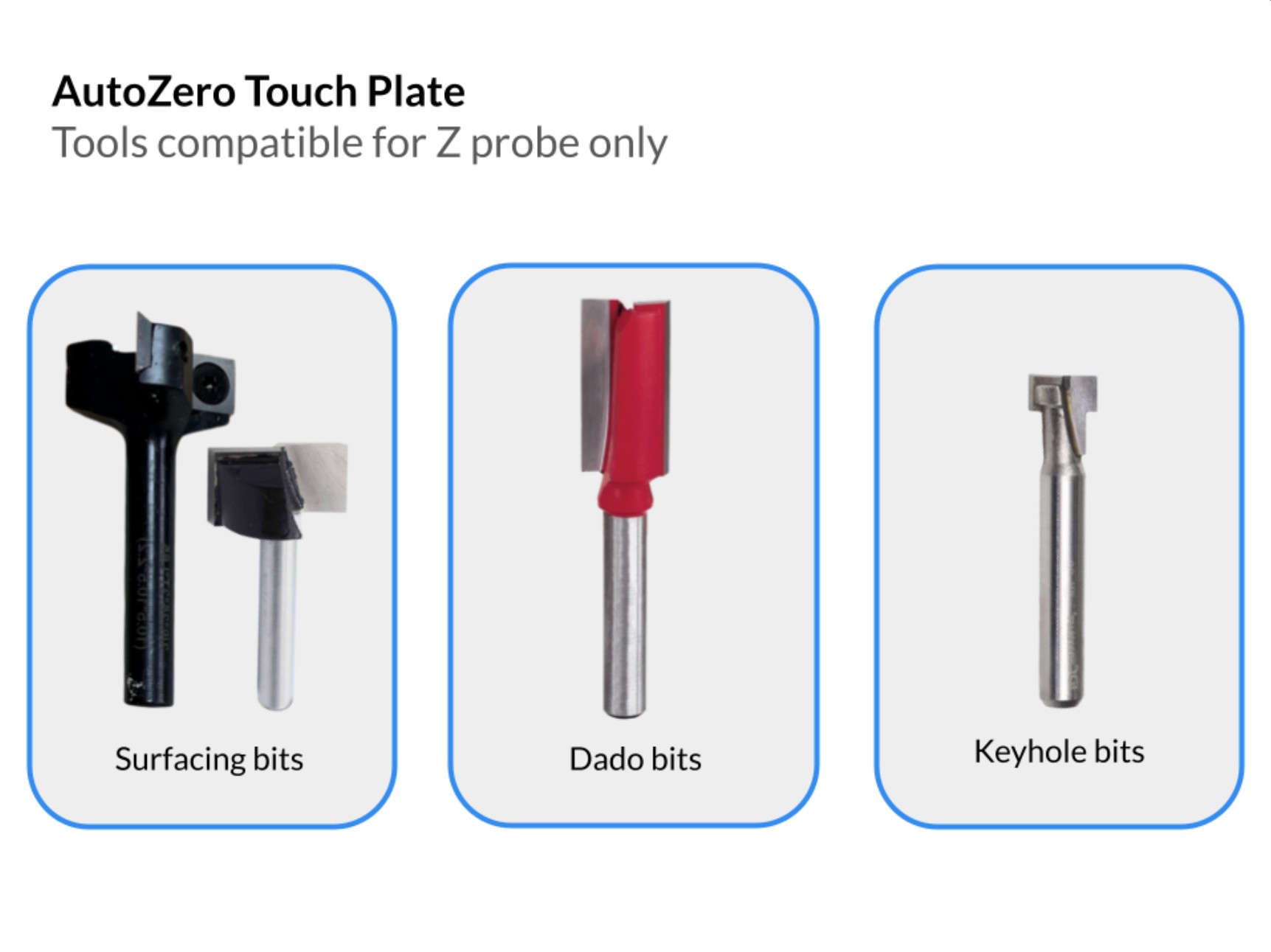
Some bits may be incompatible with the AutoZero, or may only work with the Z-probe.
-
If your tool is non-conductive, it would not work with the AutoZero
-
Make sure your work coordinates match your touch plate settings (usually G54)
-
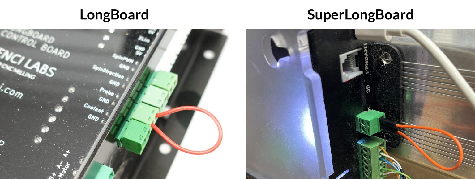
Check the controller: first make a jumper connector by placing a wire into both ends of a spare connector. Insert the jumper connector into the controller. Open gSender, begin the probing operation. You should get the green go-ahead to begin. If there is no change, the port on the controller might be the issue.
Using other Senders
Due to popular demand, we’ve created and tested macros to use the AutoZero touch plate with a variety of CNC control software beyond gSender.
Macros for CNCjs: Download for CNCjs
Macros for LinuxCNC/Buildbotics: Download for LinuxCNC/Buildbotics
Note: These macros were tested on the Buildbotics controller but they should also work with machines running LinuxCNC since they share identical variable / arithmetic formats.
Macros for other Senders: Download for other Senders
These macros will allow you to probe with the AutoZero touch plate using any CNC control software. Having said that, probing in the X and/or Y direction is a semi-automatic process in which you will need to manually halve the measure coordinate after probing.
To do so:
- Run the desired probing macro.
- If the macro involves probing in the X and/or Y axis (i.e. not probing Z alone), manually divide the coordinates you see after probing by 2.
- Enter the command G10 L20 P0 X[divided X coordinate] Y[divided Y coordinate] into the console substituting the coordinates in square brackets with ones manually calculated in step 2. If you have only probed either the X or the Y axis, you will only need to divide and substitute the coordinate for the axis which was probed.
- Home X and/or Y to check if the tool is at origin
UGS
Macros for Universal G-code Sender: Download for UGS
Note: The macros environment in UGS does not support arithmetic operations so probing with the X and/or Y axis using the AutoZero touch plate is a semi-automatic process. More specifically, you will need to click on the “Control Status (DRO)” panel and enter “/2” to halve the active coordinates in the X and/or Y after probing in these directions. If you have only probed either the X or the Y axis, you will only need to divide the coordinate of the axis which was probed.
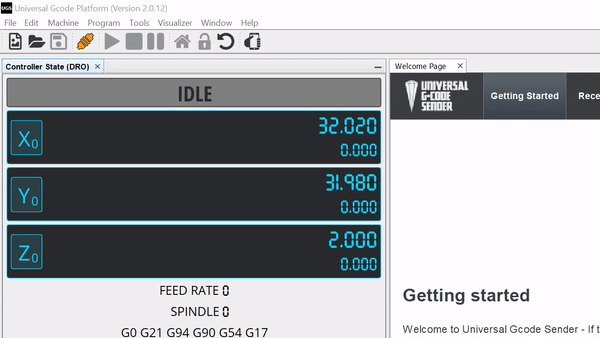
Example dividing the X and Y axis coordinates after probing in UGS