
Laser diode attachments are popular CNC add-ons that many users have installed on their LongMills and AltMills. They are capable of cutting and/or engraving wood, acrylics, delrin, leather and coated metals. They are a fun and useful tool in expanding your creativity!
Note that technical support for third-party laser attachments is limited; the instructions below should be enough to get you started. For further troubleshooting and laser product information, please reach out to the supplier.
FYI – Our LaserBeam product has been discontinued, however you can find all our documentation here.
Sourcing your Laser
These are some considerations you should make to figure out what type of laser diode is best suited for your work.
PWM Control
In the product description, check that the laser can be controlled by PWM (pulse width modulation). A 5V PWM signal is necessary to adjust laser power.
Power
Knowing whether you will be doing more cutting or engraving is essential for determining what power of laser you need. Typically 20W can achieve the best of both worlds: it can cut through 3-6mm plywood in one pass at a higher power setting, while producing clean engravings at a lower power setting.
- For faster CNCs like the AltMill, you can get the 30W as the higher machine speeds are suited to a greater wattage laser
- For simply engraving, 10W is sufficient
- Double check the power specifications. Sometimes the advertised power rating is not the average/continuous power that’s coming from your laser, which makes it weaker than expected. Furthermore some manufacturers falsify the power rating or overclock a diode with a lower rating which can lead to quick component degradation. In general, our customers have had good experiences with LaserTree lasers, see this forum discussion post for more details.
Lenses
Some lasers (like the LaserBeam) will have separate lenses available for you to switch out. These lenses are optimized for certain tasks, like cutting or engraving specific materials. But most lasers will just have the lens pre-installed, and should work for a wide range of laser tasks as long as you focus it properly.
The goal of focusing is to achieve the smallest beam possible, for the most efficient and cleanest cutting/engraving. Typically lasers will have a built-in focus adjustment mechanism, like a lever. Otherwise, you can jog your CNC machine at small increments to get the correct focal distance.
Additional Components
Air assist: This is essentially a fan or line to an air pump that’s directed at the laser module nozzle, which get more direct and effective laser penetration for cutting. Additionally it helps keeping lenses clean, and extends the longevity of the laser.
Mounting plate: The laser module will attach to the spindle/router mount on your CNC machine. Some laser kits come with a mounting plate, so check with the supplier if this is compatible with your machine. Otherwise you may need to make one yourself!
Connections: Ensure that the cable that connects the laser driver to the SLB/SLB-EXT controller has the right connector – you will need a 3-pin 3.81mm pitch Pluggable Terminal Block to plug into the controller at the LASER port.
Power supply: Check if your order comes with a power supply for your laser, or if you need to purchase one separately.
Exhaust System
You’ll want to run your laser in a space with ample ventilation and/or consider a fume extraction system, such as an inline fan and ducting for extracting the smoke outside. Fumes and particulates from engraving or cutting can be harmful. You always want to make sure the material and/or its coating you are cutting is safe to laser and does not emit hazardous fumes.
Laser Software
We recommend LightBurn – it is a 2D design and CAM software that can reliably create laser g-code that’s compatible with our machines. There are also many tutorials you can find on how to use this software. Then you can use gSender to run the g-code.
5V PWM Laser Setup Guide
Upgrade to gSender 1.6.2 or above.
Connect and open gSender.
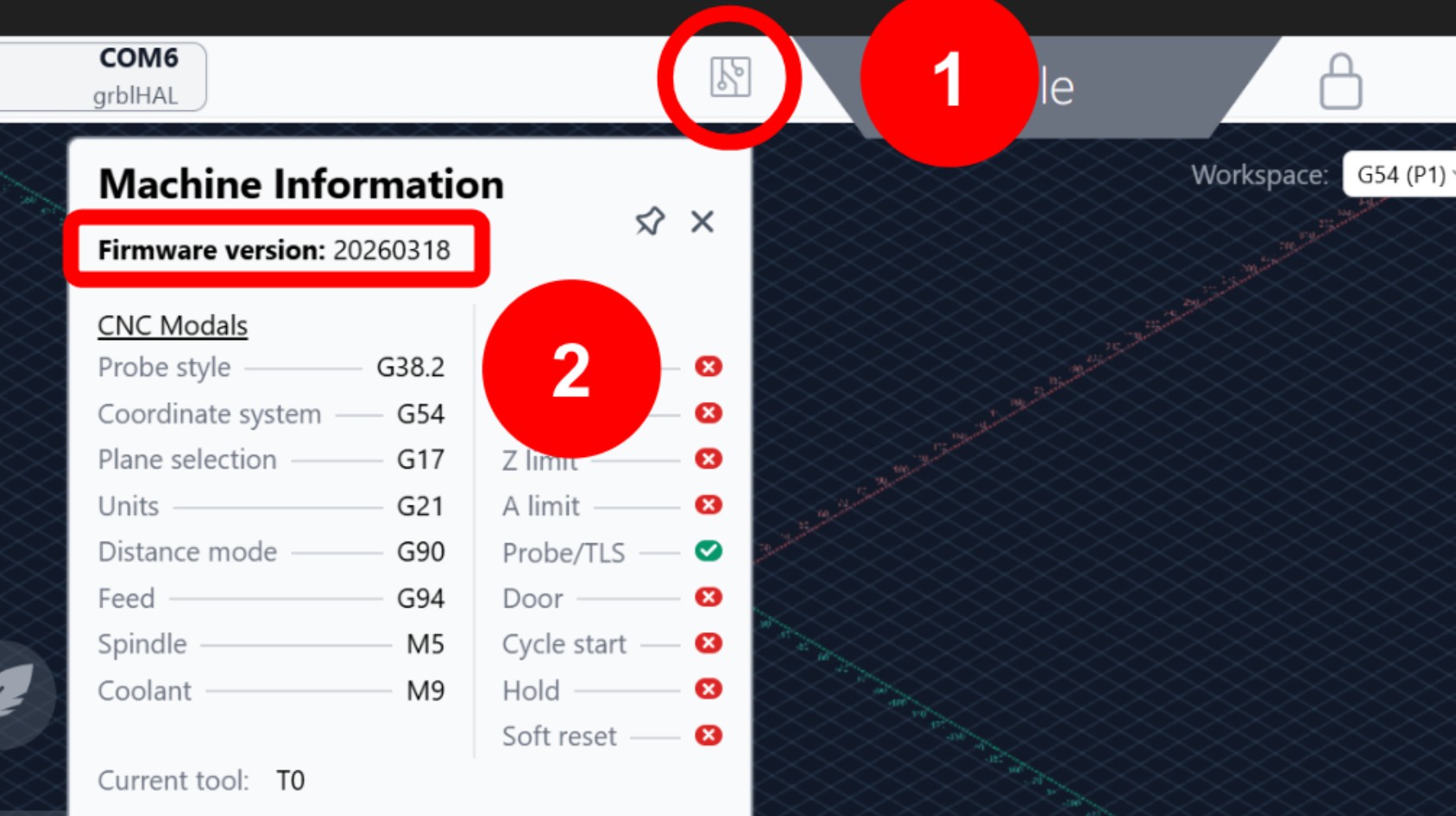
At the top of the screen, press on the circuit board icon for Machine Info. Verify which firmware version you have.
Download the correct setup file for your firmware version:
Firmware starting with 2026 and higher (e.g. 20260318, 20260525)
Older firmware (e.g. 5.0.5b, 5.0.11, 20230917)
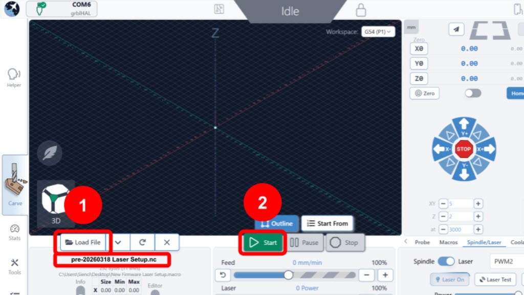
Load the file into gSender, then press Start.
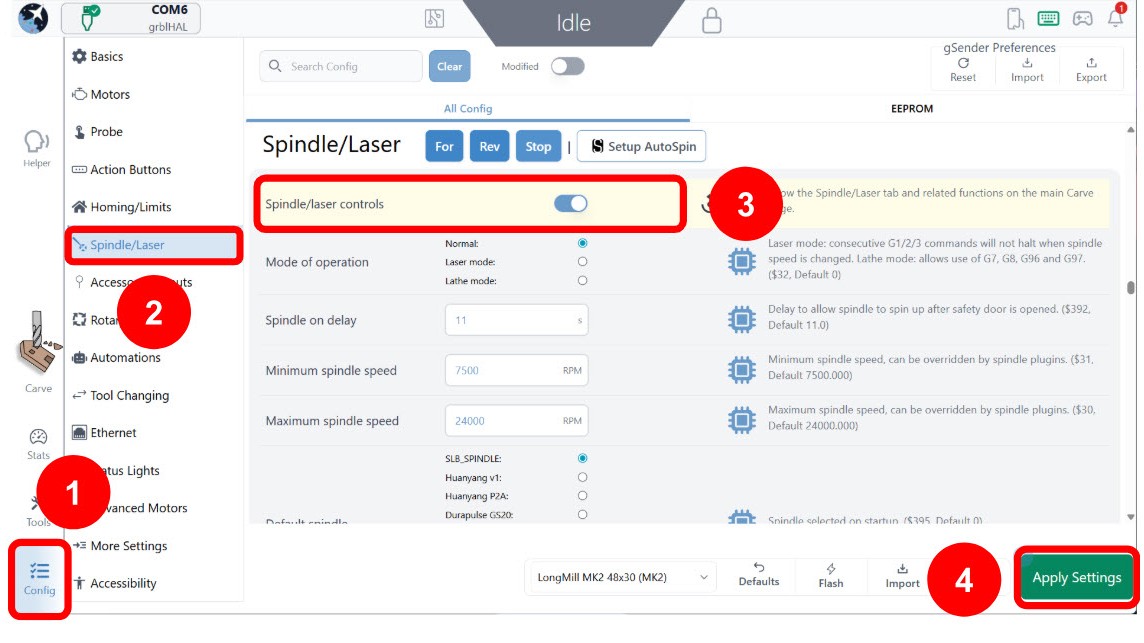
The file will take a few seconds to finish. Once it is done, go to Config. Select the Spindle/Laser heading. Toggle ON the Spindle/laser controls. Then press Apply Settings.
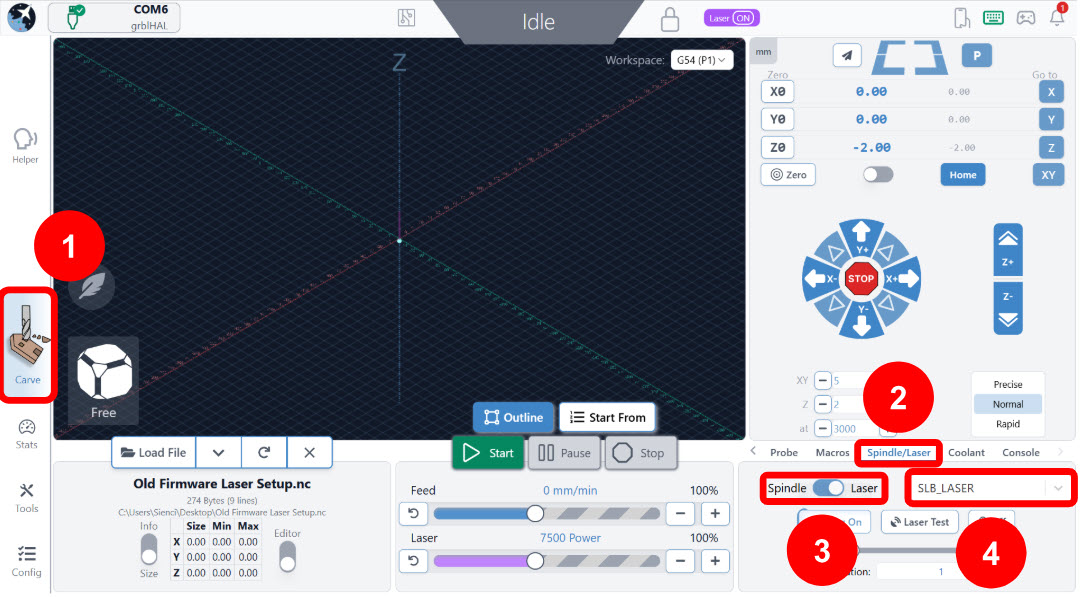
Go to the main Carve screen. Under the Spindle/Laser tab on the right side, toggle to Laser. Depending on what options are available, you can select either SLB_Laser or PWM2.
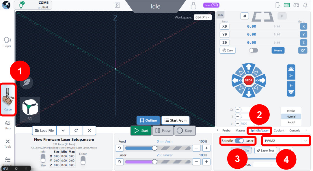
We will now test the laser signal.
If your laser is already connected to the SLB/SLB-EXT controller, we recommend disconnecting it temporarily so we can safely test.Drag the slider to 100% and selecting Laser On. Then check the PWM LAS light on your controller, which should be bright red.
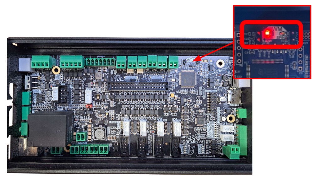
Check that power level can be changed by dragging the slider to 1-2% and selecting Laser On. Then check the PWM LAS light on your controller, it should be dimly lit now.
Turn off the signal by pressing Laser Off.
Re-connect the laser to the controller.
If all this works, you should now be all set up to run your laser on gSender!
See the next section if you want to zero your jobs using an end mill instead of the laser.
Laser Offsets
To easily zero your laser job, we recommend setting up your “laser offsets”, which is the distance and direction your laser is mounted in relation to the spindle/router. You would zero with your spindle/router as normal; the laser offsets will automatically apply when you switch into Laser mode. Then machine will know where the laser is and start the job at the right spot.
You only need to set up the laser offsets once!
-
Make sure you have an end mill installed to your spindle/router.
-
Secure a scrap piece of wood. Make sure it is large enough – we will use this to mark our spindle/router position and laser position.
-
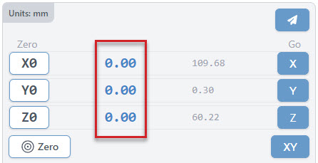
Set your XY zeros on gSender. The blue coordinates should turn to O.
-
Mark the zero position on the wood with a pencil.
-
If you aren’t wearing them yet, wear your laser safety glasses!
-
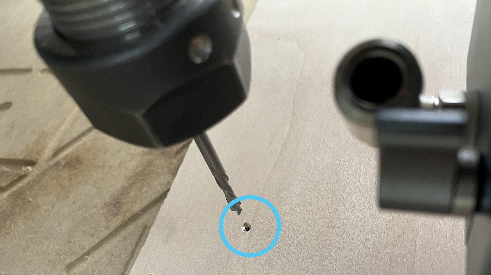
Turn ON the laser at low power (1-2%) to mark a pin hole on the wood. Then turn OFF the laser.
-
Jog the machine in the X and Y axis to hover the end mill directly above the pinhole. Try to be as accurate as possible.
-
Check the blue X and Y coordinates on gSender, you should see number values, possibly with negative signs (-). Write these values down without the negatives.
-
Determine the offset value by checking the position of the laser with respect to the spindle.
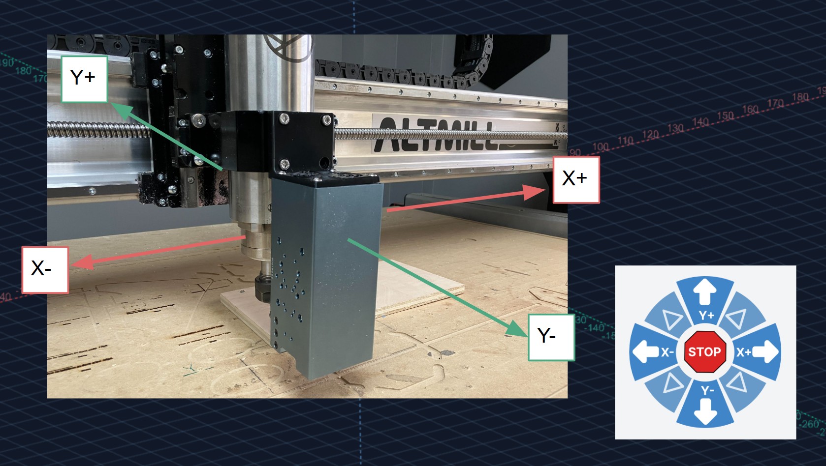
Example: If the laser is mounted in front of the spindle, it is the in the -Y direction. So the Y offset value is the number value with a negative sign (-). If the laser is mounted to the right of the spindle, it is in the +X direction. So the X offset value is the number value WITHOUT a negative sign. -
To enter the final offset values go to Config. Under Spindle/Laser find the Laser X Offset and Laser Y Offset settings. Input your values there.
-
Press Apply Settings and turn OFF/ON your controller to have the changes take effect.