Setting up any style of touch plate on your machine is easy. Since it only requires a ‘closed’ connection between two wires, you can use all sorts of plate designs from a thin metal sheet to a more common block style. Once wired, the last step is to check that your g-code sender understands the shape of your touch plate and how you plan to use it.
This guide covers set up and use of our standard, block-style Touch Plate. If you have a different or custom block-shaped touch plate, these steps can also be applied for software setup and usage.
Wiring
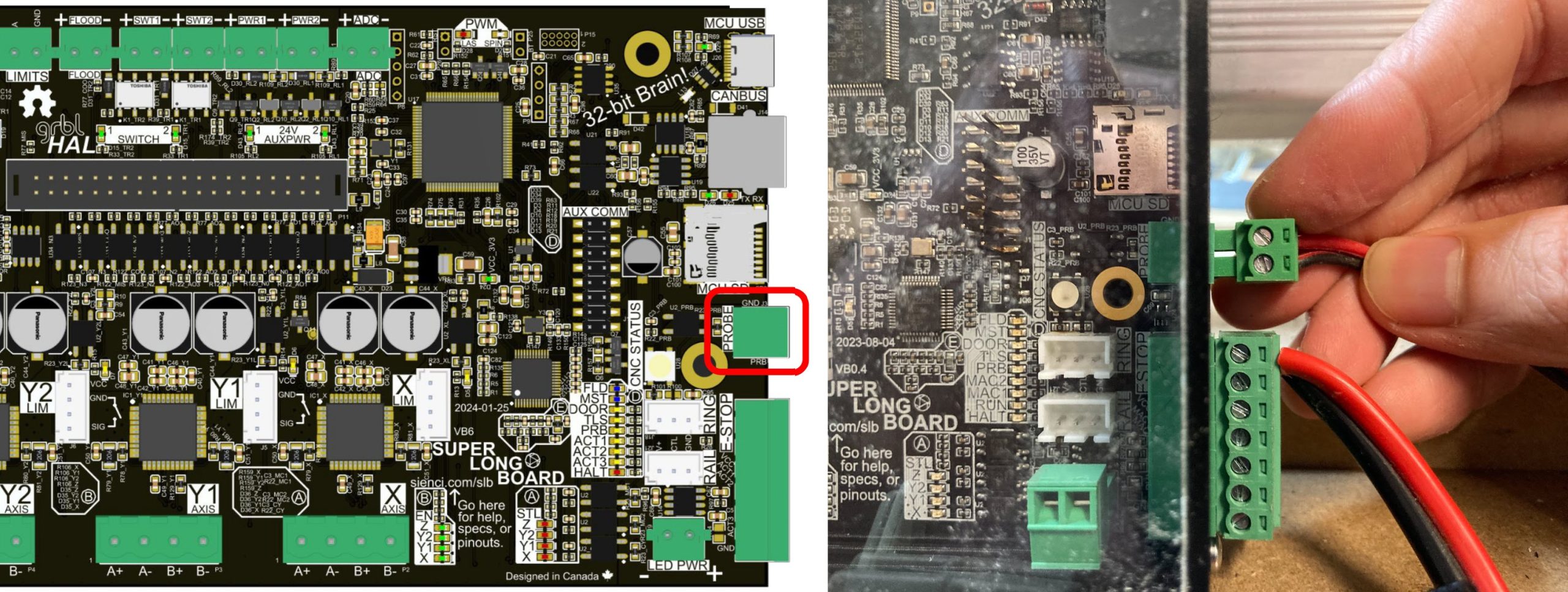
Our touch plates come mostly pre-wired but sometimes a green connector will need to be attached – you can find it on the PROBE port of your SLB/SLB-EXT controller. These terminal connectors have a built-in clamping system that you can open and close using the screw heads.
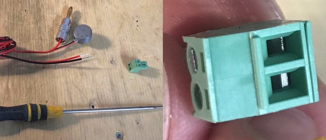
Use a flat head screwdriver to clamp down on the wire ends, ensuring the red and black wires are in the correct order as in the photo. Give the wires a small tug to check they are secured. Plug the connector back into the board once finished.
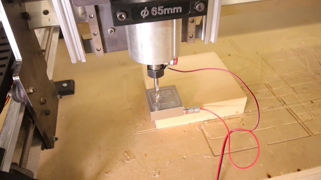
At the other end of the wiring harness will be a magnet and a banana plug. The touch plate has two different holes you can insert the banana plug into, for your convenience. Connect the banana plug into the touch plate. Place the magnet onto the router collet nut.
Software Configuration
With wiring complete, let’s move on to setting up your g-code sender to work with the touch plate. gSender and UGS (UGSPlatform) are easiest to configure for this style probe so we’ll show setup for both below.
Current
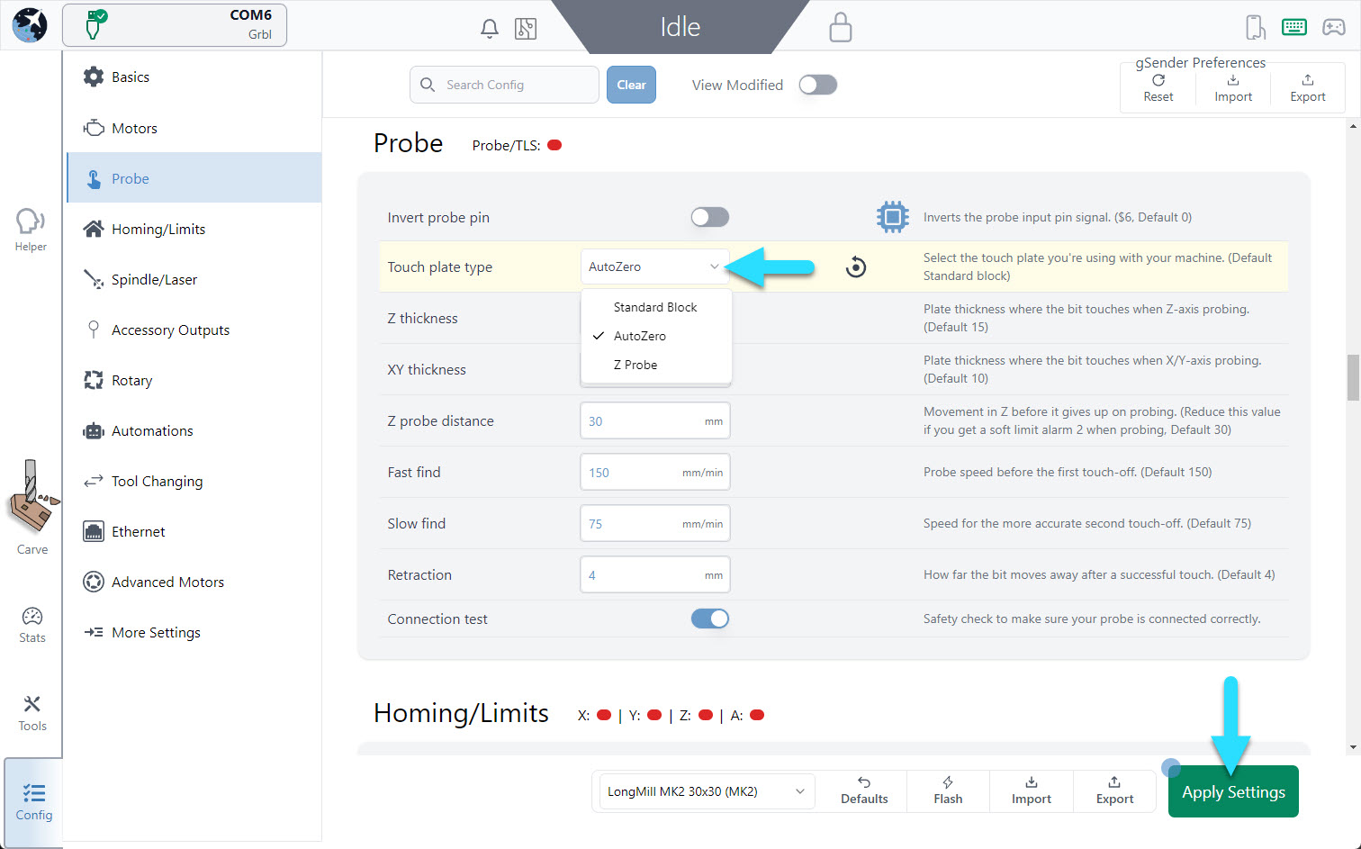
Go into Config, and under Probe, make sure the Touch plate type is set to Standard Block. Then press Apply Settings.
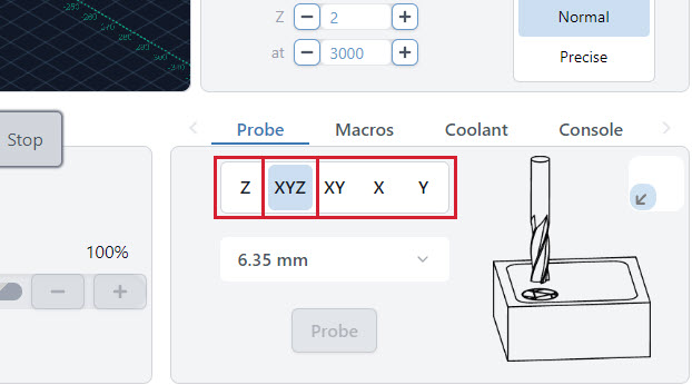
All probing happens in the Probe tab on the main Carve screen. Here you can select what type of probing you’d like to perform, as well as enter the tool size you’ll be using.
- Z: Finds the Z height only.
- XYZ: Finds the zero point on the front, left corner of your material in all axes.
- XY, X, Y: Finds the zero point in the X and/or Y directions only.
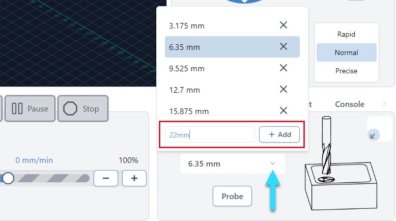
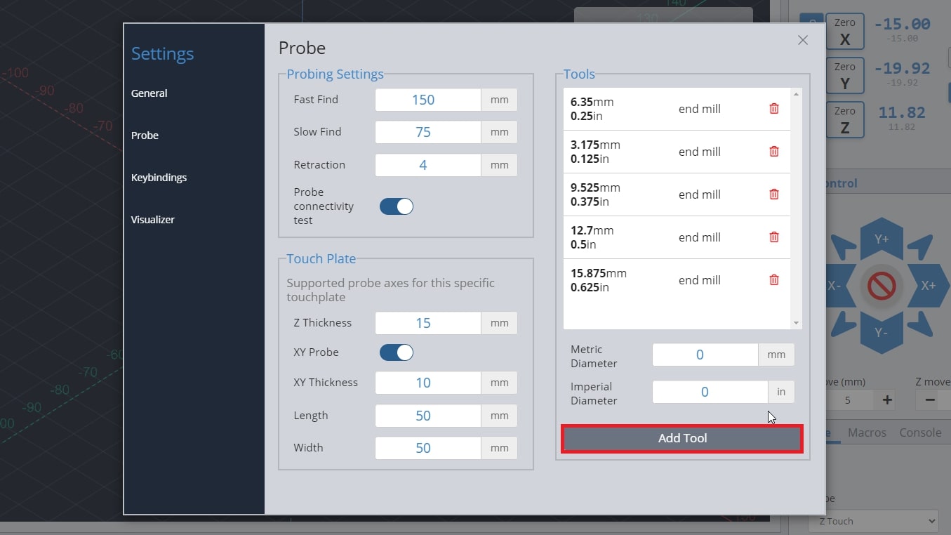
You can also add tools here if you want the probe widget to remember your most commonly used tools.
Classic gSender
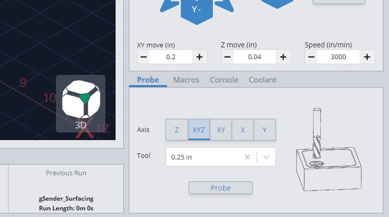
All probing happens in the Probe tab in the main window. Here you can select what type of probing you’d like to perform as well as select the tool you’ll be using or you can type in the tool size manually.
- Z: Finds the Z height only.
- XYZ: Finds the zero point on the front, left corner of your material in all axes.
- XY, X, Y: Finds the zero point in the X and/or Y directions only.
You can also add tools here if you want the probe widget to remember your most commonly used tools.
UGS
UGS comes with a simple plugin that allows for your machine to send the commands to your machine to utilize the touch plate for finding the X, Y, and Z-axis.
Start by going to the top of your screen and clicking Window ➜ Plugin ➜ Probe Module. You will see a new tab appear on your screen.
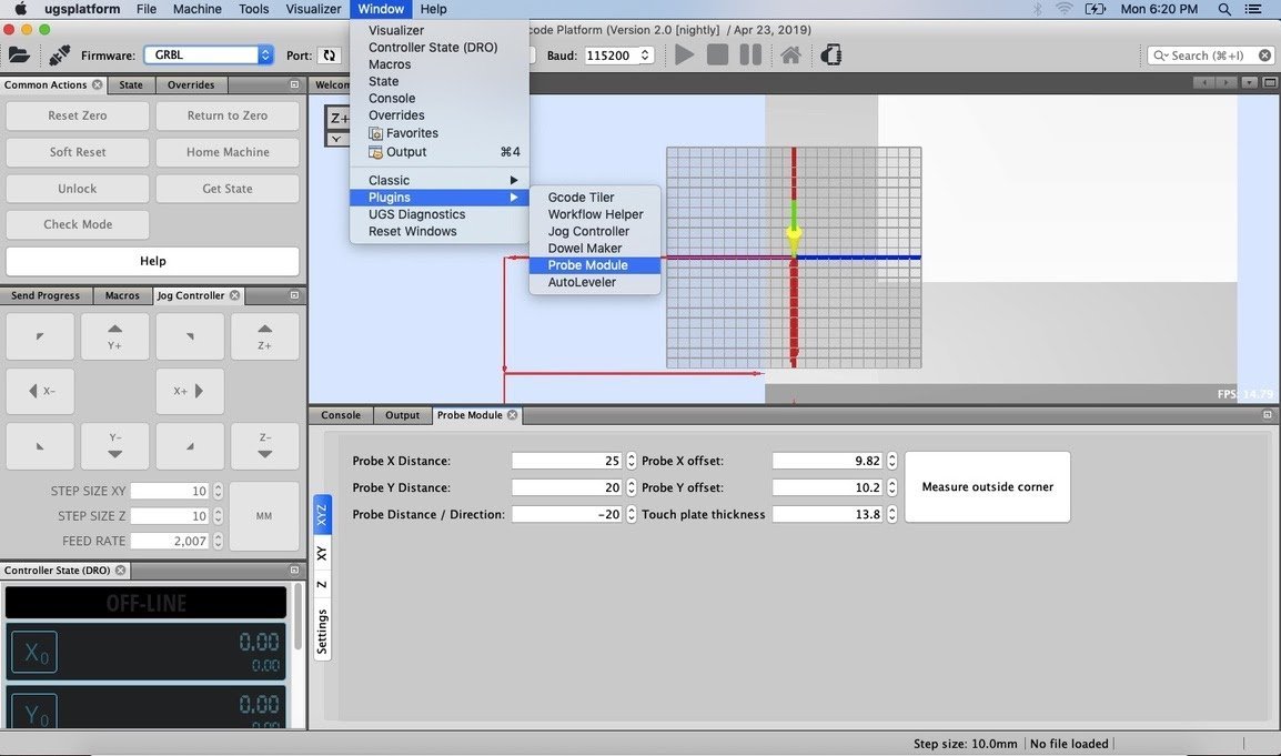
Next, we will change a few settings. Click on the “Settings” button on the plugin.
- Units: choose between millimeters and inches. For this guide, we will be using millimeters.
- End Mill Diameter: the diameter of the end mill you will be using. You can find this diameter based on your manufacturer’s specs, or you can measure it yourself.
- Fast Find Rate: the speed the machine will move to touch off the touch plate on the first pass. Set this to 150.
- Slow Find Rate: the speed the machine will move to touch off the touch plate on the second pass. Set this to 25.
- Retract Amount: how far your tool moves away from the touch plate on its first touch off. Keep this setting at 1.
Within the left side of the plugin, you’ll also see a few more tabs
- XYZ: Finds the origin/datum point on the corner of your material in all axes.
- XY: Finds the origin/datum point in the X and Y direction only.
- Z: Finds the Z height only.
In these sections, makes sure that these settings are changed. If your section does not have that setting available to change, you can skip it. This means that in the XYZ tab you’ll enter all these settings, in the XY tab you’ll only use the settings pertaining to the x and y-directions, and in the Z tab you’ll only use the settings pertaining to the z-direction.
- Probe X Distance: 25
- Probe Y Distance: 25
- Probe X Offset: 10
- Probe Y Offset: 10
- Probe Distance/Direction: -15 (make sure this value is negative)
- Touch Plate Thickness: 15
Using your Touch Plate
We’re pretty much ready to go!
-
Make sure the magnet is on the router’s collet nut, and the banana plug is in the block.
-
Place the touch plate on the front left corner of your material. Make sure that both of the inner faces of the touch plate are contacting the edges of your material.
-
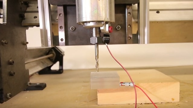
Install your tool, in this example we have a 1/4″ end mill.
-
Jog your machine to position the cutting tool about 10mm (½”) above the circular logo on the touch plate.
Current
-
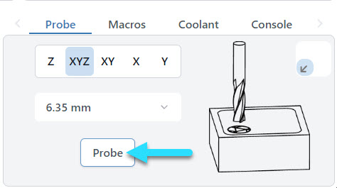
In the ‘Probe’ tab, choose which axis to probe for and the diameter of the bit you’re using
- Choose XYZ and 1/4″ to follow the example
- The bit size can be selected from the drop-down of saved bits, or can be typed in manually.
-
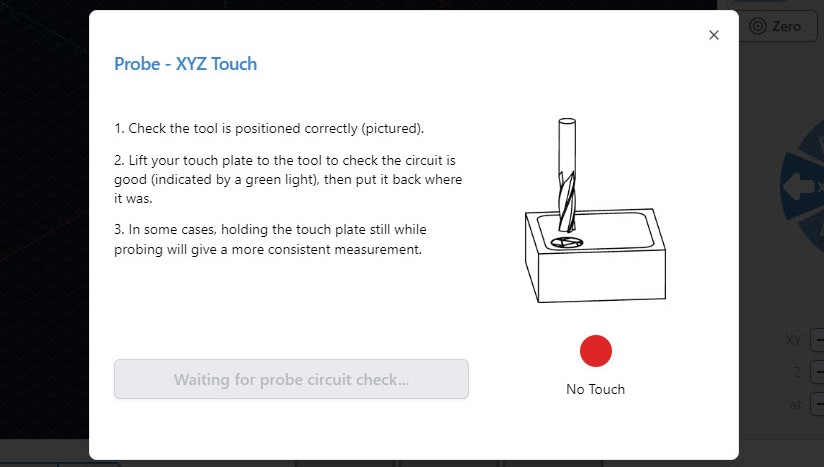
Press the ‘Probe’ button and you’ll get a pop-up window to confirm bit position and electrical connection.
You can either bring the touch plate to the end mill or touch the banana plug and magnet together. Make contact a few times just to confirm there is conductivity, as the red circle should flicker to green, and a blue ‘Start Probe’ button appears.
-
Press ‘Start Probe’ – the machine will move to probe three sides of the touch plate, twice on each side. There should not be any crashing or abrupt movement.
-
Once the process is over, remove the touch plate components from the machine then press the blue ‘XY button in the Go column. The bit should move to the front left corner of the stock material. Press the blue ‘Z’ button in the Go column. The bit should move to the material’s surface.
-
If the probing was unsuccessful, then you will see an ‘ALARM’. To bring it out of the alarm state, press the pulsing ‘Unlock’ button in the middle of the visualizer. An unsuccessful probing cycle can result from an incorrectly positioned probe or starting too far outside the circular logo. Be sure to verify your setup before attempting another probing cycle.
Classic gSender
-
In the ‘Probe’ tab, choose which axis to probe for and the diameter of the bit you’re using
- Choose XYZ and 1/4″ to follow the example
- The bit size can be selected from the drop-down of saved bits, or can be typed in manually.
-
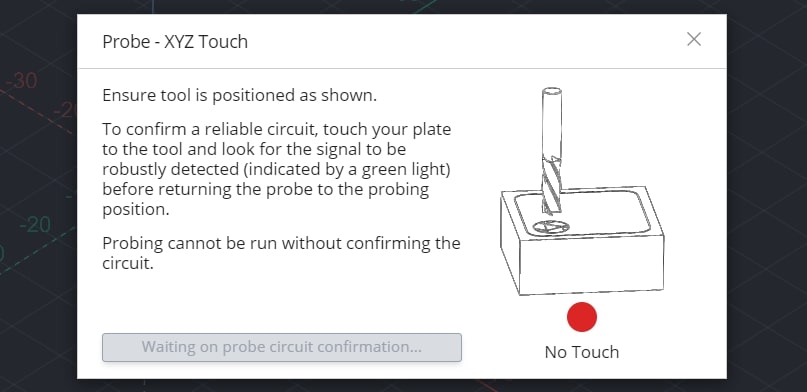
Press the ‘Probe’ button and you’ll get a pop-up window to confirm bit position and electrical connection.
You can either bring the touch plate to the end mill or touch the banana plug and magnet together. Make contact a few times just to confirm there is conductivity, as the red circle should flicker to green, and a blue ‘Start Probe’ button appears.
-
Press ‘Start Probe’ – the machine will move to probe three sides of the touch plate, twice on each side. There should not be any crashing or abrupt movement.
-
Once the process is over, remove the touch plate components from the machine then press the blue ‘XY button in the Go column. The bit should move to the front left corner of the stock material. Press the blue ‘Z’ button in the Go column. The bit should move to the material’s surface.
-
If the probing was unsuccessful, then you will see an ‘ALARM’. To bring it out of the alarm state, press the pulsing ‘Unlock’ button in the middle of the visualizer. An unsuccessful probing cycle can result from an incorrectly positioned probe or starting too far outside the circular logo. Be sure to verify your setup before attempting another probing cycle.
UGS
Open up the probing window in UGS and in the XYZ tab press “Measure outside corner”. The LongMill will go through a cycle to probe and take its measurements.
If the probing function is successful, then the machine should return the bit back to the starting point where you initiated the probing cycle. You should notice that the ‘DRO’ (Digital Read Out) on UGSPlatform changes to reflect the measurements, the current position being offset a little in the X and Y and quite a bit offset in the Z.
You can check that it’s now zeroed on the material corner by first taking the touch plate off the material and removing the magnet from the router collet before pressing “Return to Zero”.
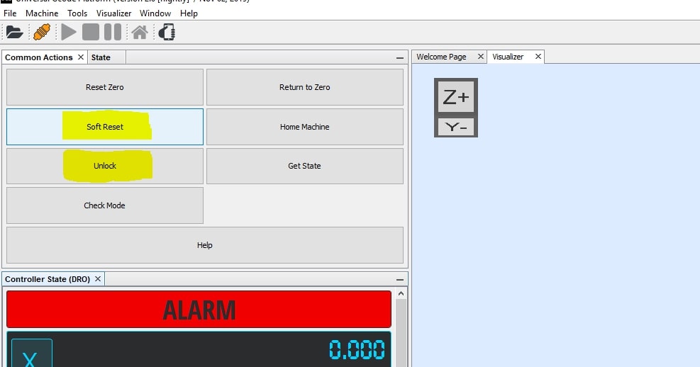
If the probing was unsuccessful, then it’ll be indicated by the cutting bit not returning to where you started the probe cycle or the machine will be put into an ‘ALARM’ state. To bring it out of the alarm state, press the “Soft Reset” button followed by the “Unlock” button and that will put the machine back into its ‘IDLE’ state. An unsuccessful probing cycle can result from an incorrectly positioned probe, the magnet not attached to the collet properly, starting too far outside the circular logo, and the probe not being plugged into the controller. Be sure to verify your setup before attempting another probing cycle.
If everything went according to plan, you should now see your bit at the material corner like this:
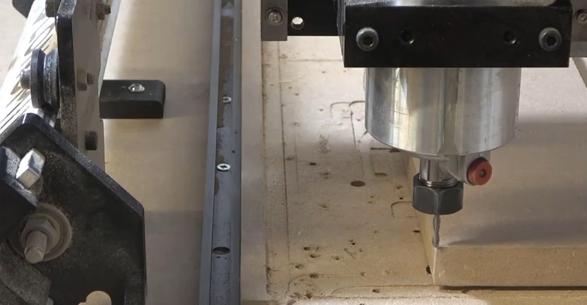
Remove your magnet and set your touch plate aside, and you’re done!
Probing Options
Here are some other options you can use when probing:
- For Z probing:
- Flip your touch plate upside down and place it on top of the material that you want to find the top of.
- Position the cutting tool so that it’s above the indented part of the touch plate.
- For XY probing:
- Place the touch plate on the front left corner of your material. Make sure that both of the inner faces of the touch plate are contacting the edges of your material.
- Jog your machine to position the cutting tool at the outer corner of the plate, lowered down from its top surface.
- For X and Y probing:
- Place the touch plate on the front left corner of your material. Make sure that both of the inner faces of the touch plate are contacting the edges of your material.
- Jog your machine to position the cutting tool away from the X or Y face.
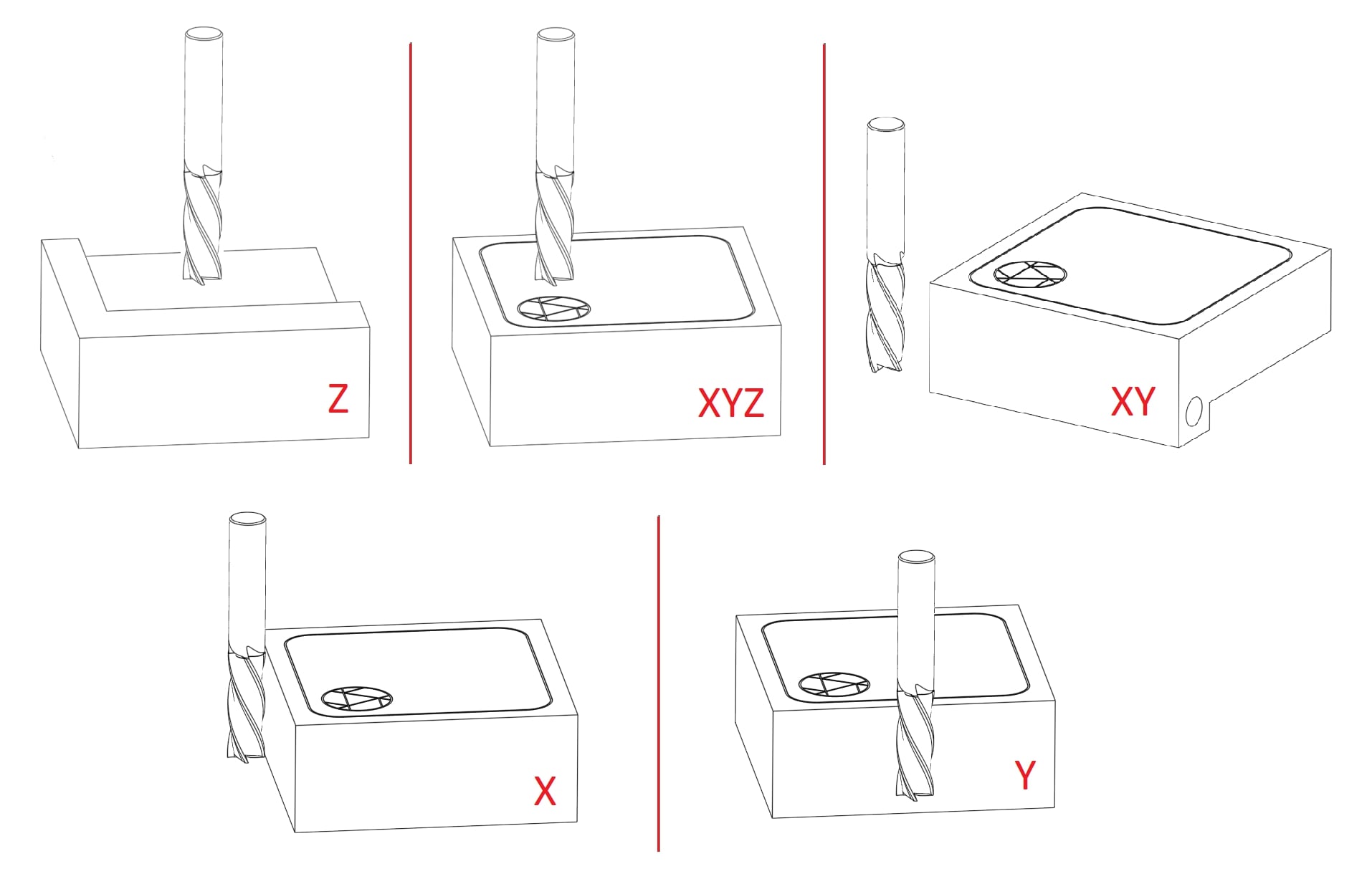
Concluding notes:
You may have some issues with using your touch probe if your cutting tool is:
- Irregularly shaped (v bits, dado bits) and the side of the widest point of the bit does not touch off on the side of the touch plate
- Non-conductive
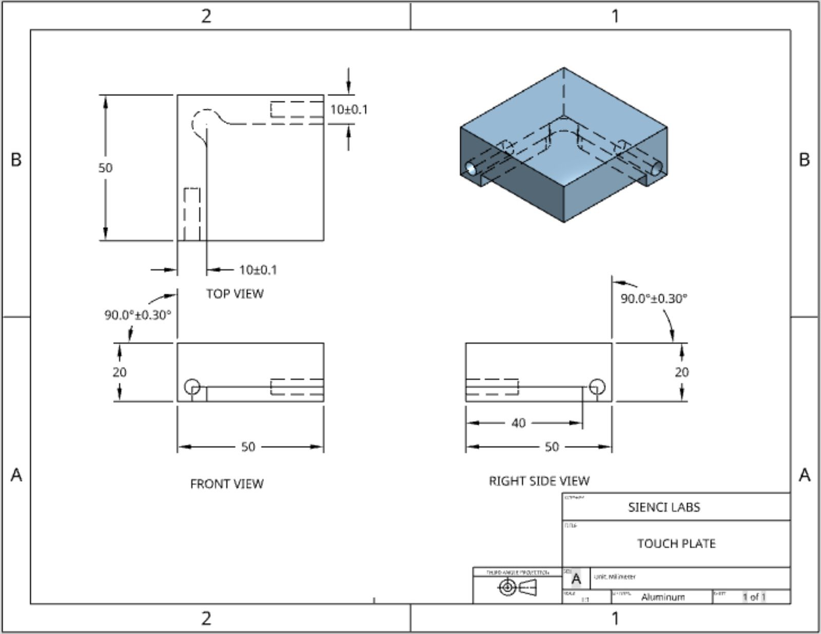
- You’ve entered the incorrect plate dimensions. You can refer to our own design below or the dimensions supplied by your third-party touch plate manufacturer: