

Switching to the Closed Loop Stepper Motors (CLSM) from the open loop motors is easy. The main difference between the open loop and the closed loop motors is that the open loop motors lack positional feedback making them prone to “skipping steps” under load. With closed loop motors there is a feedback system that helps in monitoring their positions which enables them to self-correct errors, improve accuracy and operate more efficiently. If you have a LongMill with the SLB – EXT, go to CLSM SLB-EXT for installation instructions.
Unboxing
Your upgrade kit will include a new SLB-LITE, 4 closed loop motors, 4 inductive sensors, a new 48 volt power supply and more! Check out the list below and contact our team if any parts are missing.
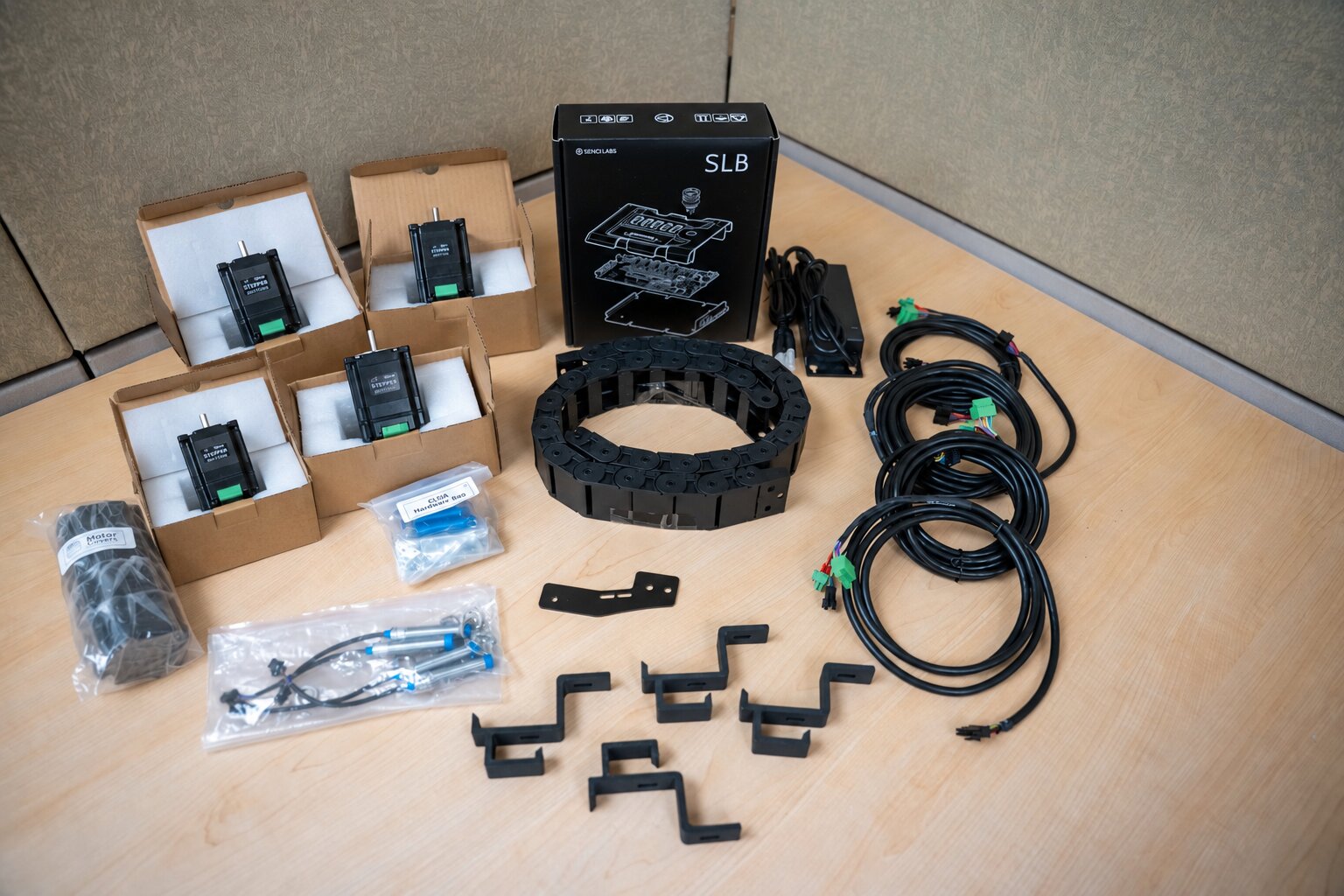
The following components are included in the upgrade kit and are shown together in the photo below:
- SLB-LITE
- NEMA 23 Motors (x4)
- Motor Covers (x4)
- 40mm blue or silver aluminum standoffs (x16)
- 24V power supply
- Larger Drag chain 18×26
- Drag chain brackets (x4)
- Drag chain holder mount
- Inductive sensors (x4)
- Inductive sensor Y mount bracket (x2)
- MK3 sheathed motor cable set
- M5-10mm hex head screws (x2)
- M5-12mm socket head screws + washers (x8)
- M5 Nylock nuts (x2)
- M5 T-nuts (x6)
- M5-55mm socket head screws (x4, for motor covers)
- 3/4″ Wood screws (x4)
Motors
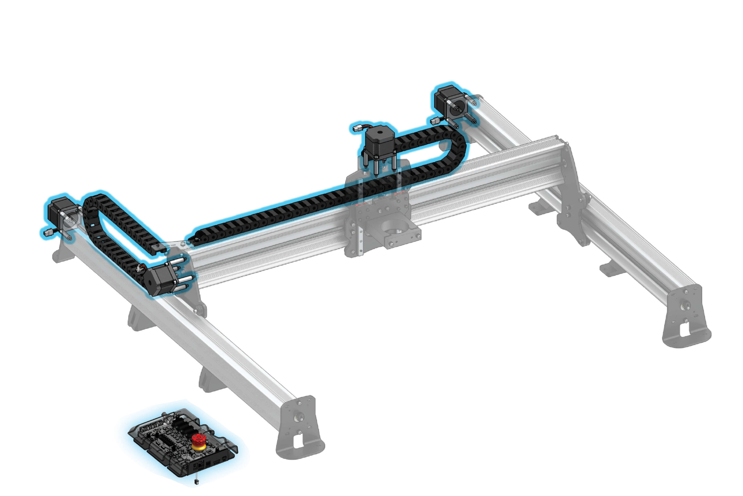
This process should take approximately 2-3 hours. To begin, jog machine to the front/center of your wasteboard, and pull the table away from the wall if possible. You can also remove your router or spindle to give you a bit more room and open all of the links on your drag chains with a small flat head screwdriver to prepare for this upgrade. Let’start with the motors!
Remove Stepper Motors
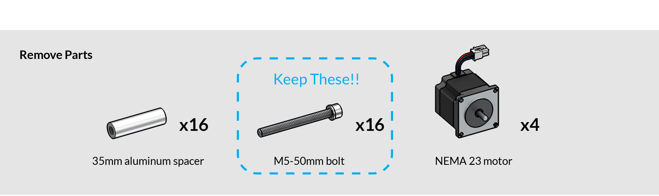
We will be removing all 4 of the open loop motors (X-axis, Z-axis + 2 Y-axis motors) The process is the same for all 4 of the motors. We begin with the X-axis motor, on the left side of the machine.
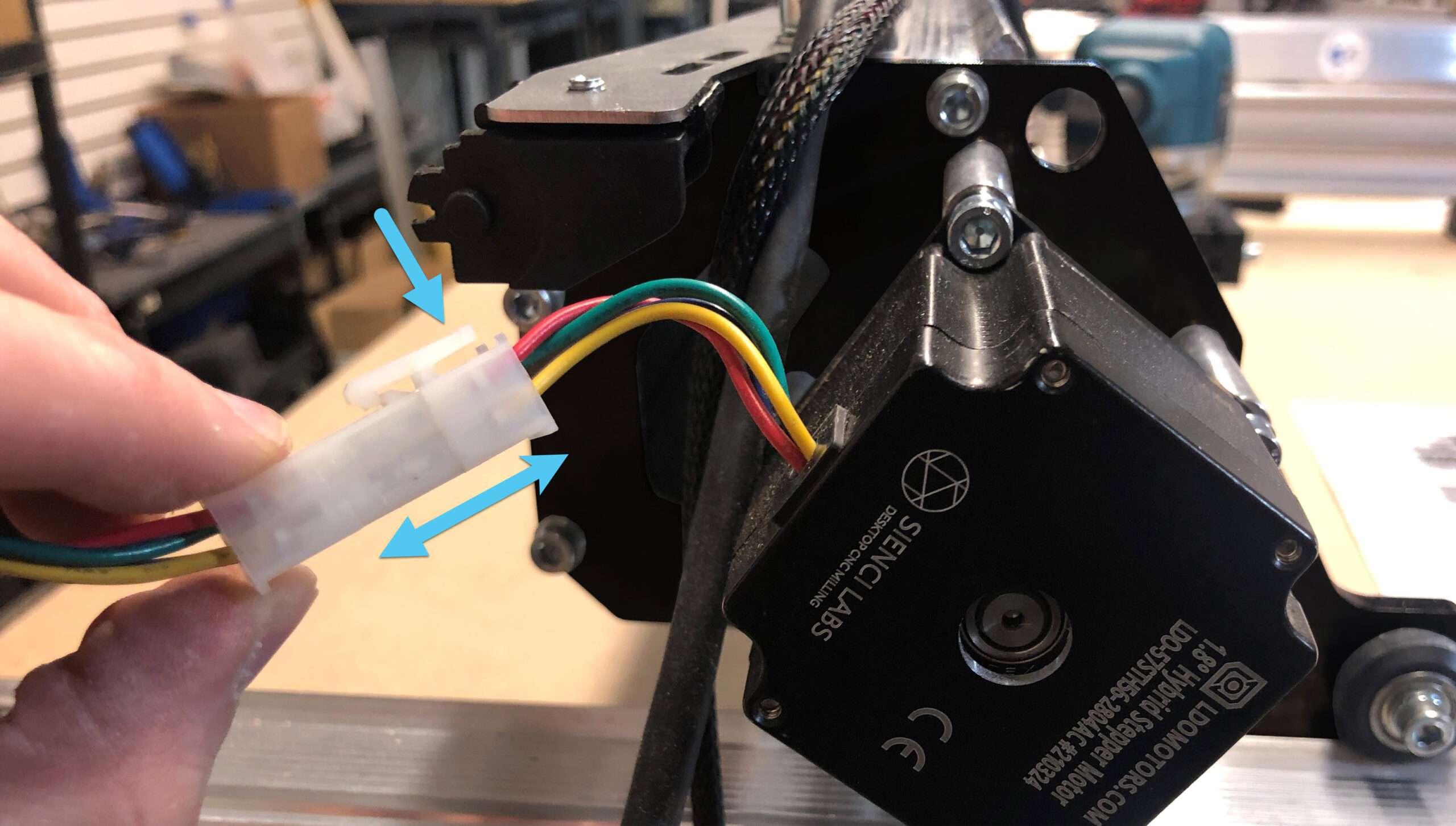
Unplug the open loop stepper motor at the white connector. This is done by pressing on the short end of the white connector, then pulling the connection apart.

Using an M5 Allen key, remove the M5-50mm bolts and set them aside. We will be using them to install the new motors. You can use a drill to speed up the process here, and if the screws are too tight, use the M5 Allen key to loosen them. You will not need to keep the aluminum spacers, replacements are in the new kit.
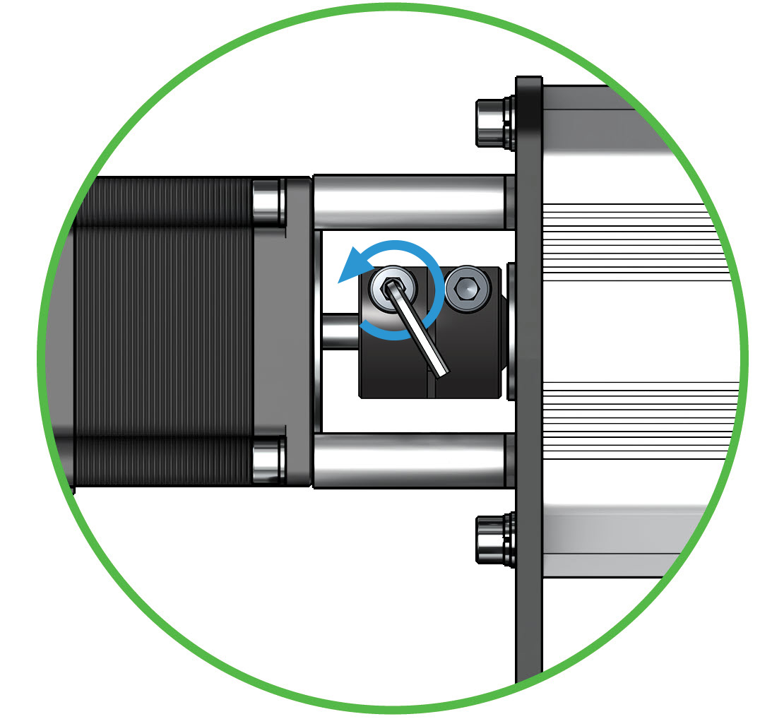
Loosen the bolt on the coupler that is closest to the motor. This will allow you to lift each motor free from the motor shafts.
Now that we’ve pulled the X-axis motor from the motor shaft, proceed to do the exact same 3 steps with the Z-axis motor and both Y-axis motors.
- Unplug connector
- Remove 4 standoffs
- Loosen coupler.
Install the New Motors
Ok, nicely done! We will now run the process we just completed, in reverse. Grab the new closed loop motors, the blue/silver standoffs, and the M5-50mm bolts we removed in the previous step above.
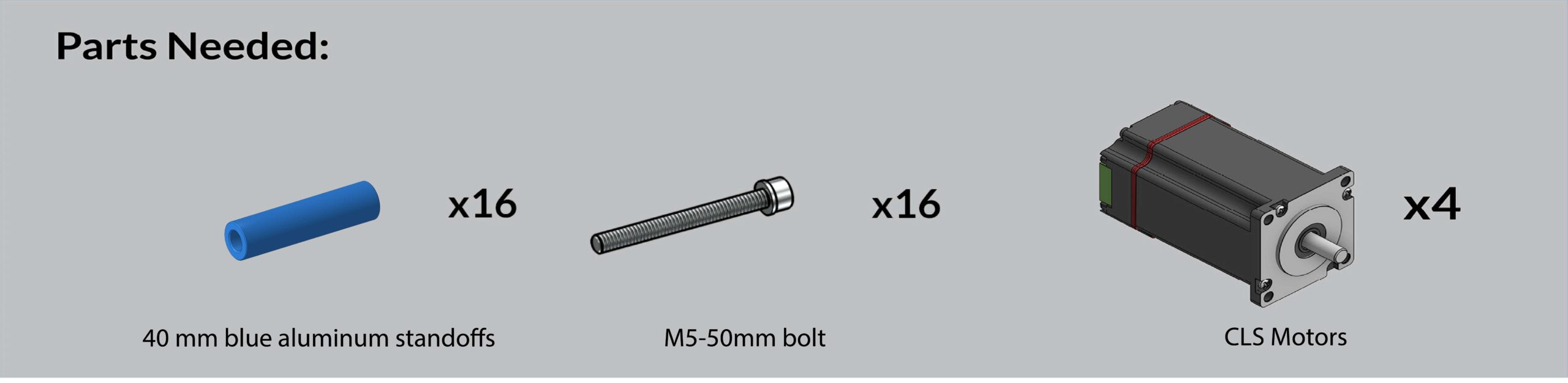
Let’s begin by inserting each bolt into it’s corresponding hole in the motor, then sliding each M5-50mm bolt into a matching 40mm spacer. Using either a drill or an M5 allen key, tighten each spacer/bolt combo.
Note – The latest motors do not have a red stripe around them, they are all black & you may receive either blue or silver standoffs.
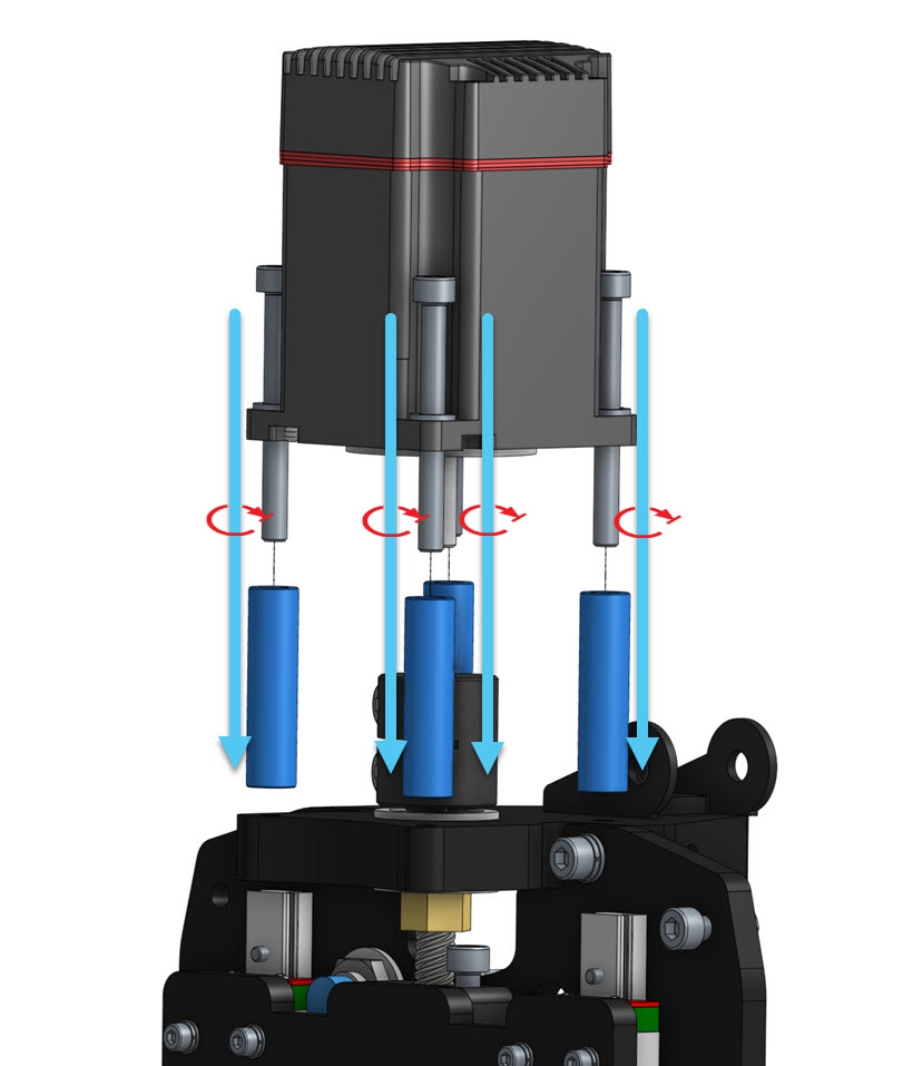
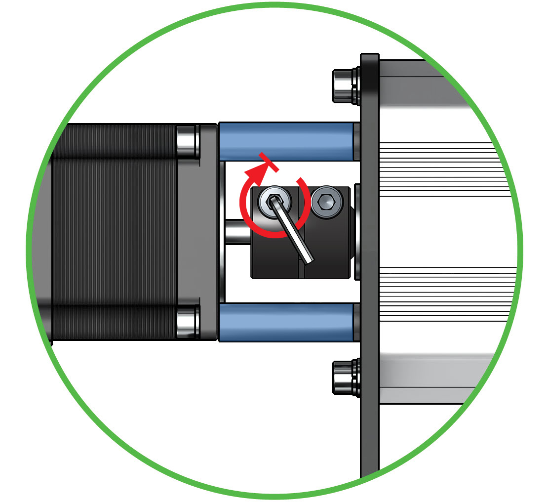
With the new motor shaft fully seated in the coupler, turn the coupler bolt closest to the new motor with the M5 allen key until tight.If everything has come together well so far, you should be able to now check that the lead screw can spin relatively easily.
Now that we’ve replaced the one motor, proceed to do the exact same 3 steps with the remaining motors.
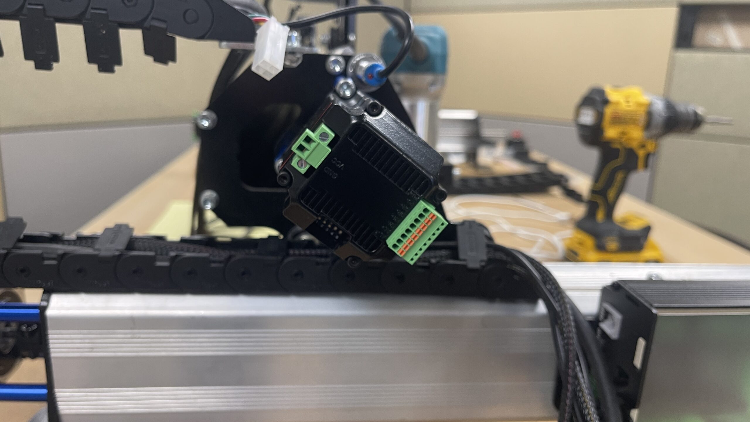
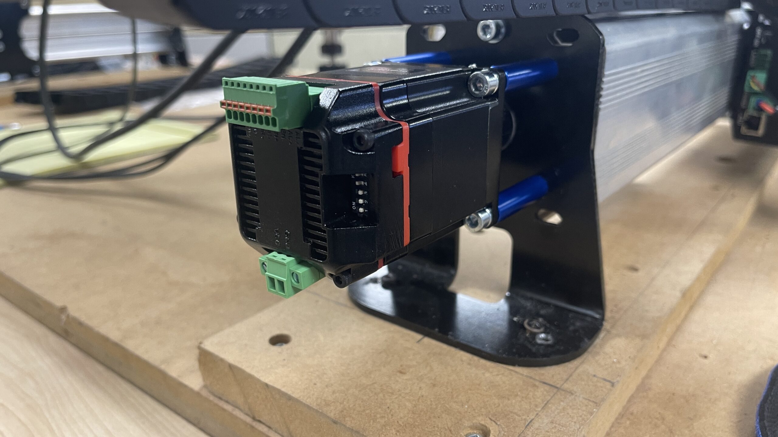
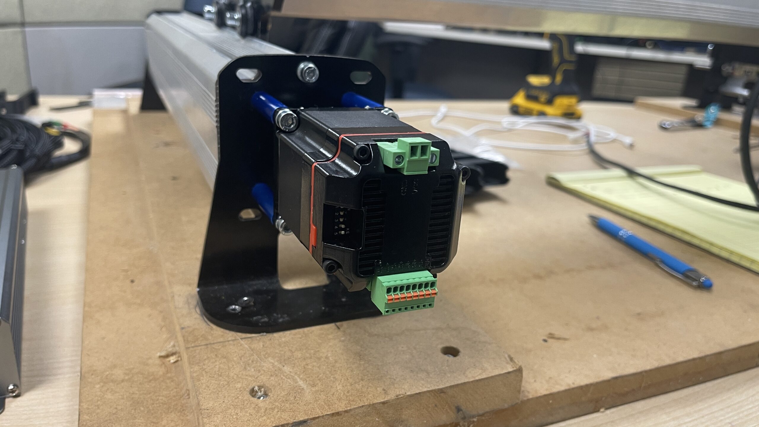
- Swap out spacers
- Tighten down M-50mm screws
- Tighten coupler
If you have dust shields on your y-axis rails, replace the two M5-50mm screws with the included M5-55mm screws on the inside standoffs/spacers for both y-axis motors. This will allow the dust shields to sit on those new screws slightly.
Dip Switches
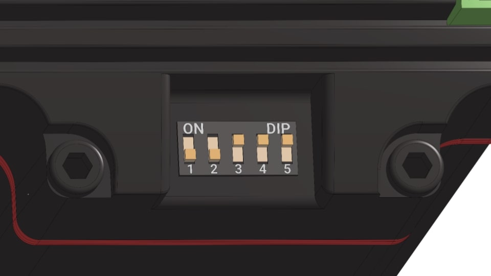
The motors should arrive with the DIP switches in the correct position for use with the stock settings.
Check to ensure the DIP switches on the X and Y axis motors follow the order of: 1-5: OFF, OFF, ON, ON, ON
Sensors
With the upgraded motors and SLB LITE, you will receive 4 new limit switches (inductive sensors) with short pigtail connectors. In this section, we will swap out the 3 originals and install 4 new ones. Once complete, you will have a sensor on your Z axis, X axis and one on each Y axis, for a total of 4 sensors!
Having an extra limit switch on your Y axis, allows you to home each axis (Y1 and Y2) individually.
Remove Old Sensors
Locate your X-axis & Z-axis sensors and loosen the nuts, then remove them.
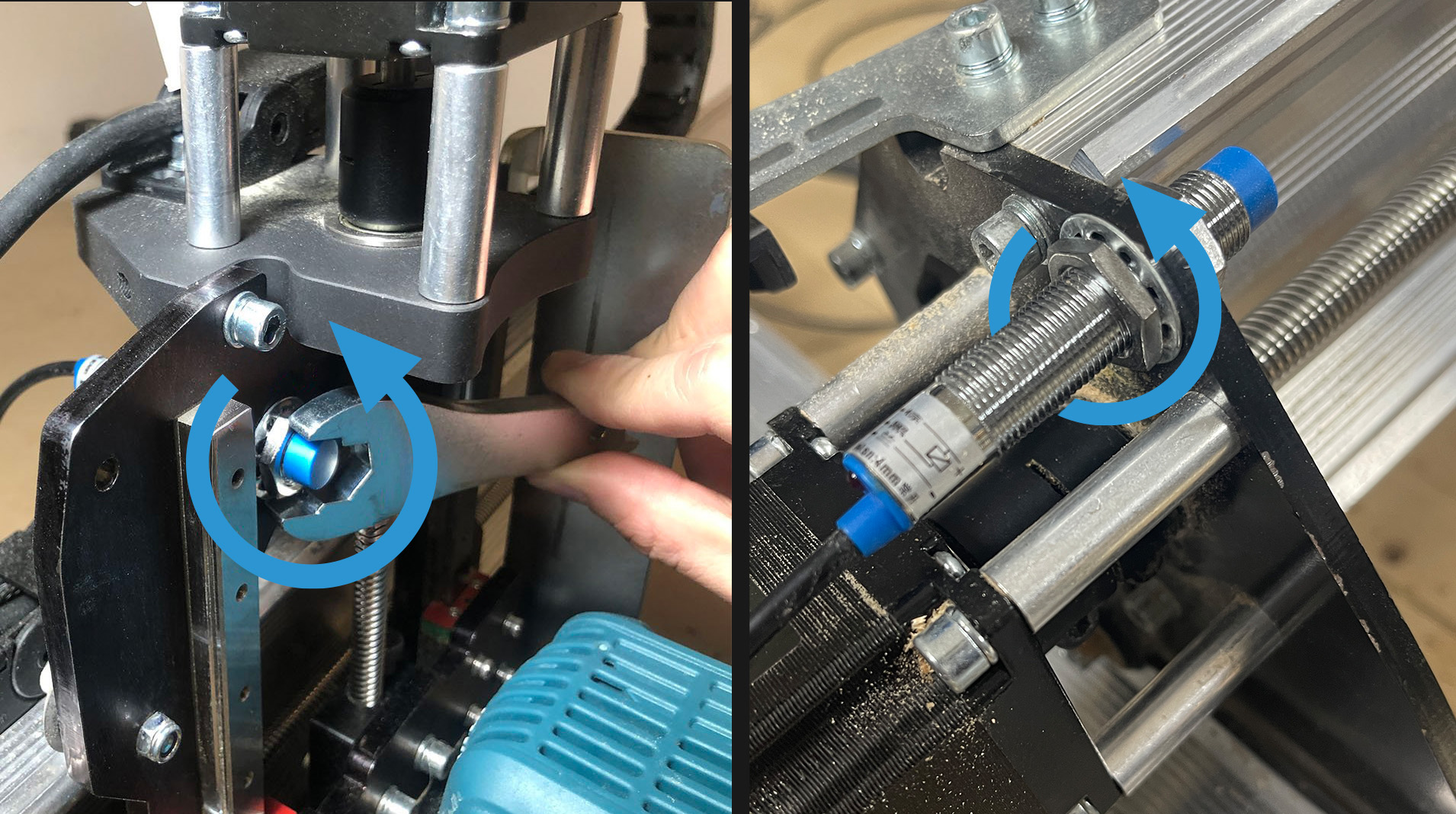
For your Y-axis sensor, remove the bracket from the rail, we will be moving it to the back of the rail, and to the bottom.
Install New Sensors
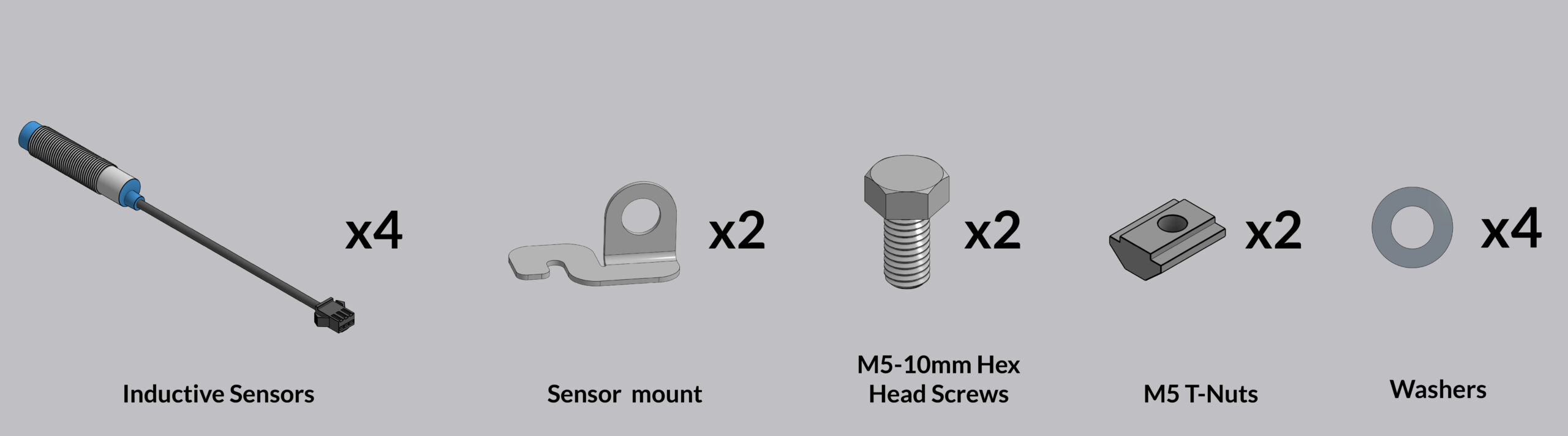
For the Z & X-axis, you can simply pop the new pigtail limit switches into the old holes, and tighten the nuts down again. This process is exactly the same for the Z-axis and the X-axis, but differs a bit for the two Y-axis switches.
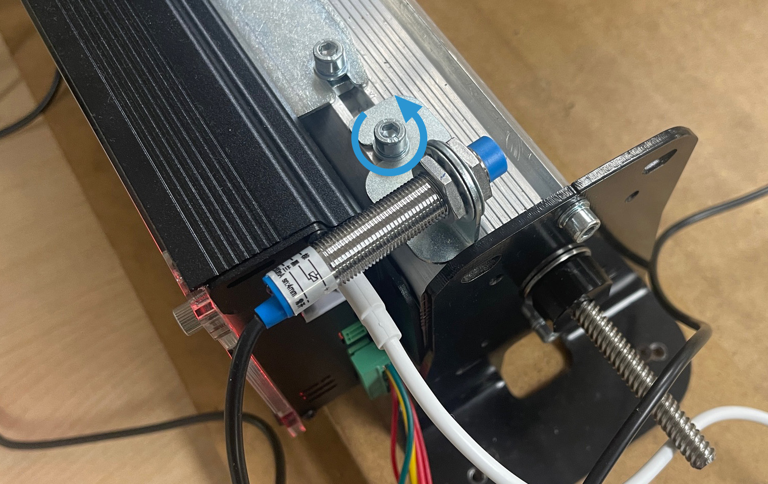
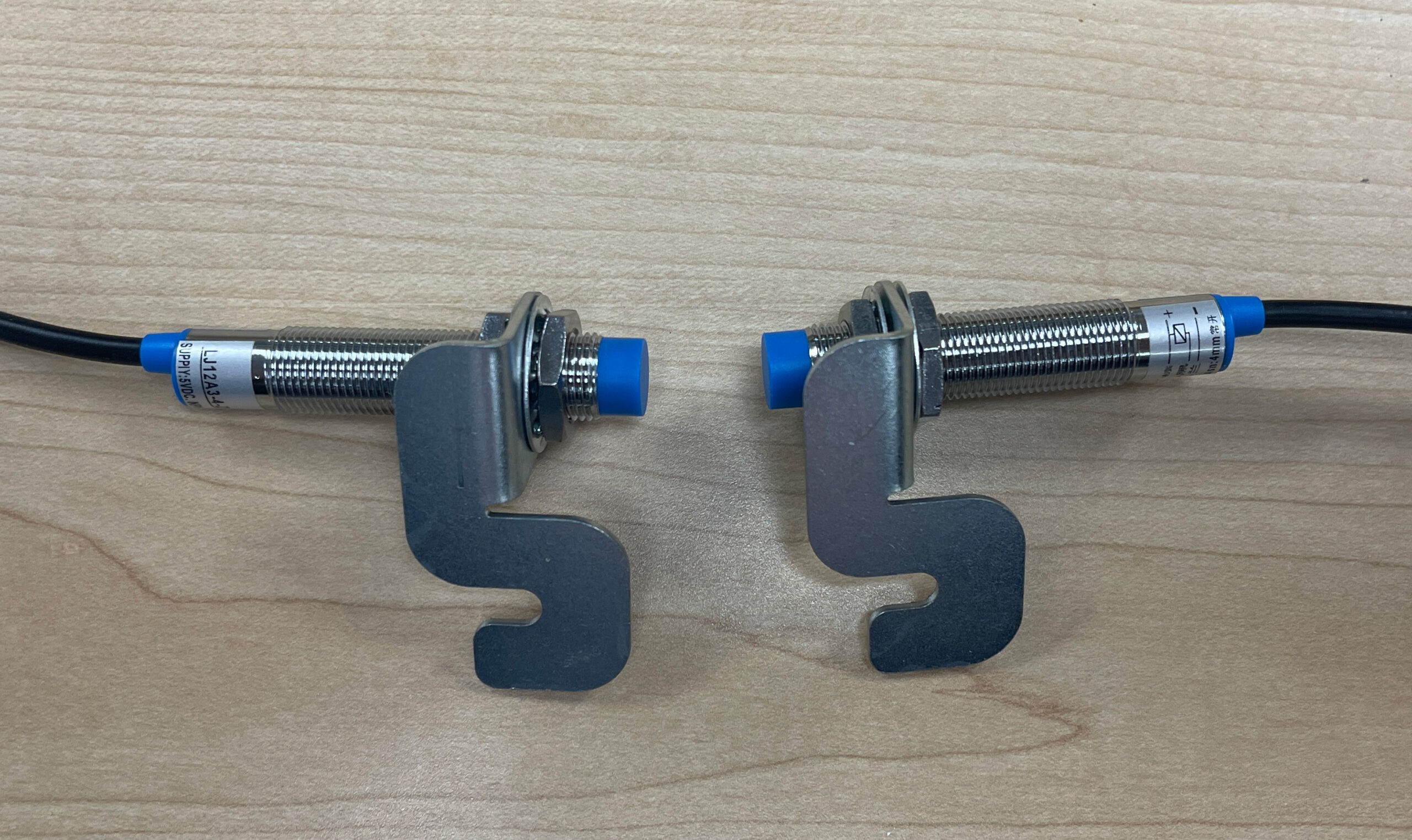
For the Y-axis, we will be using a bracket to mount the sensor under the Y-axis rails, and pushing them to the back left and right corners. Mount each sensor onto a bracket as shown.
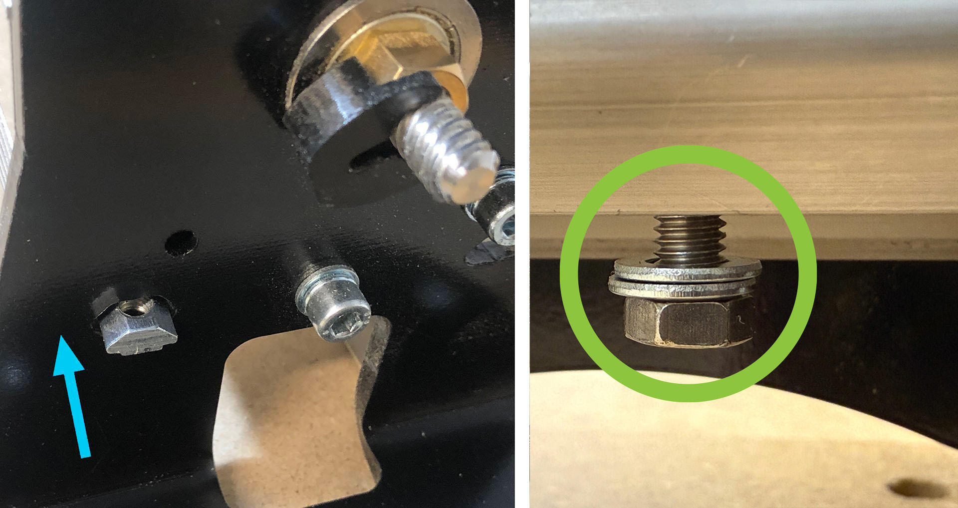
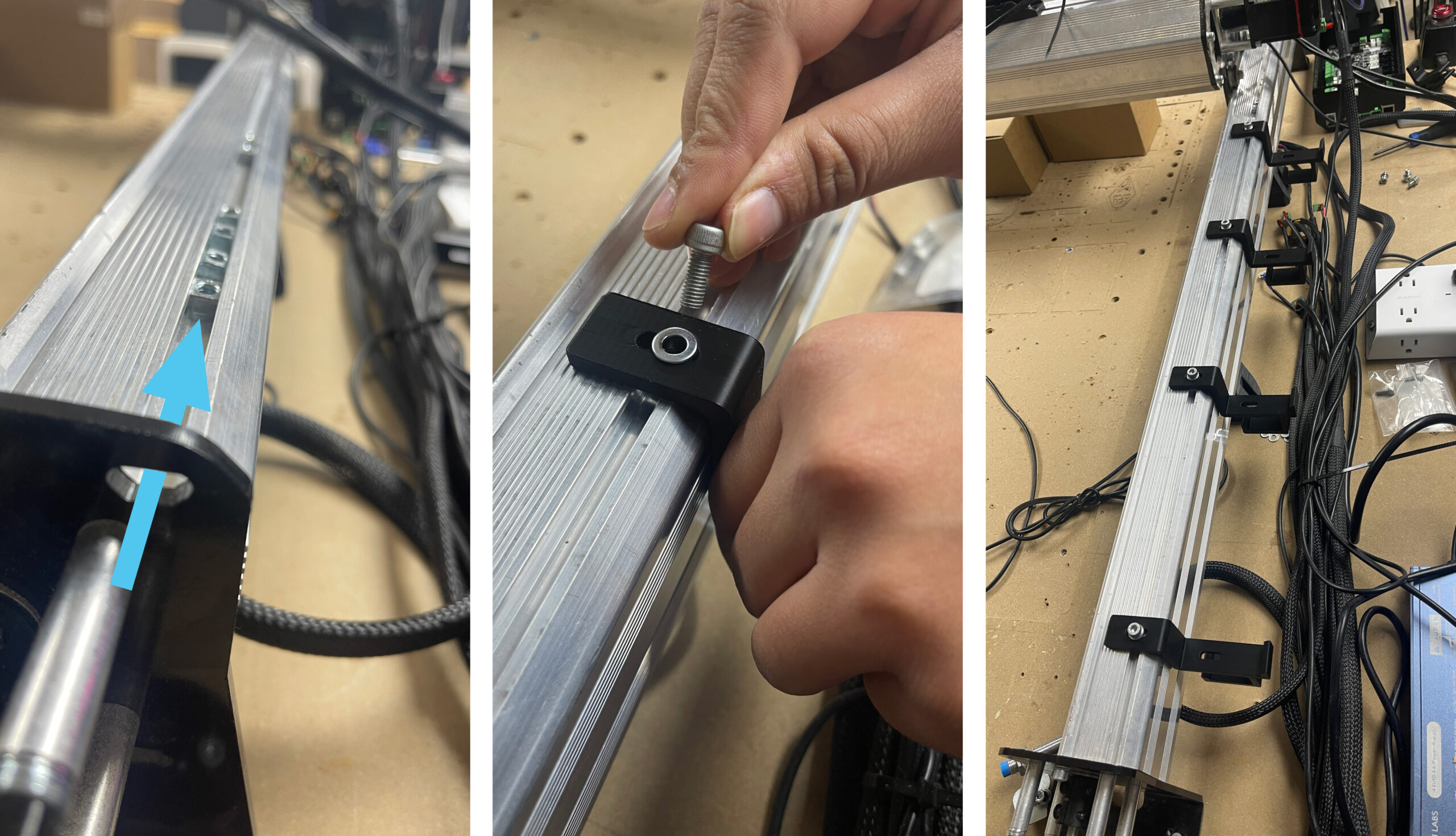
Slip an M5-T Nut into the slot at the back of both Y-axis rails and secure it with an M5-10mm hex head screw, with two washers. Do not tighten this all the way down yet, as we will be sliding the bracket onto it. You can use the wrench that shipped with your LongMill, or one you have in your shop to assist in this step.
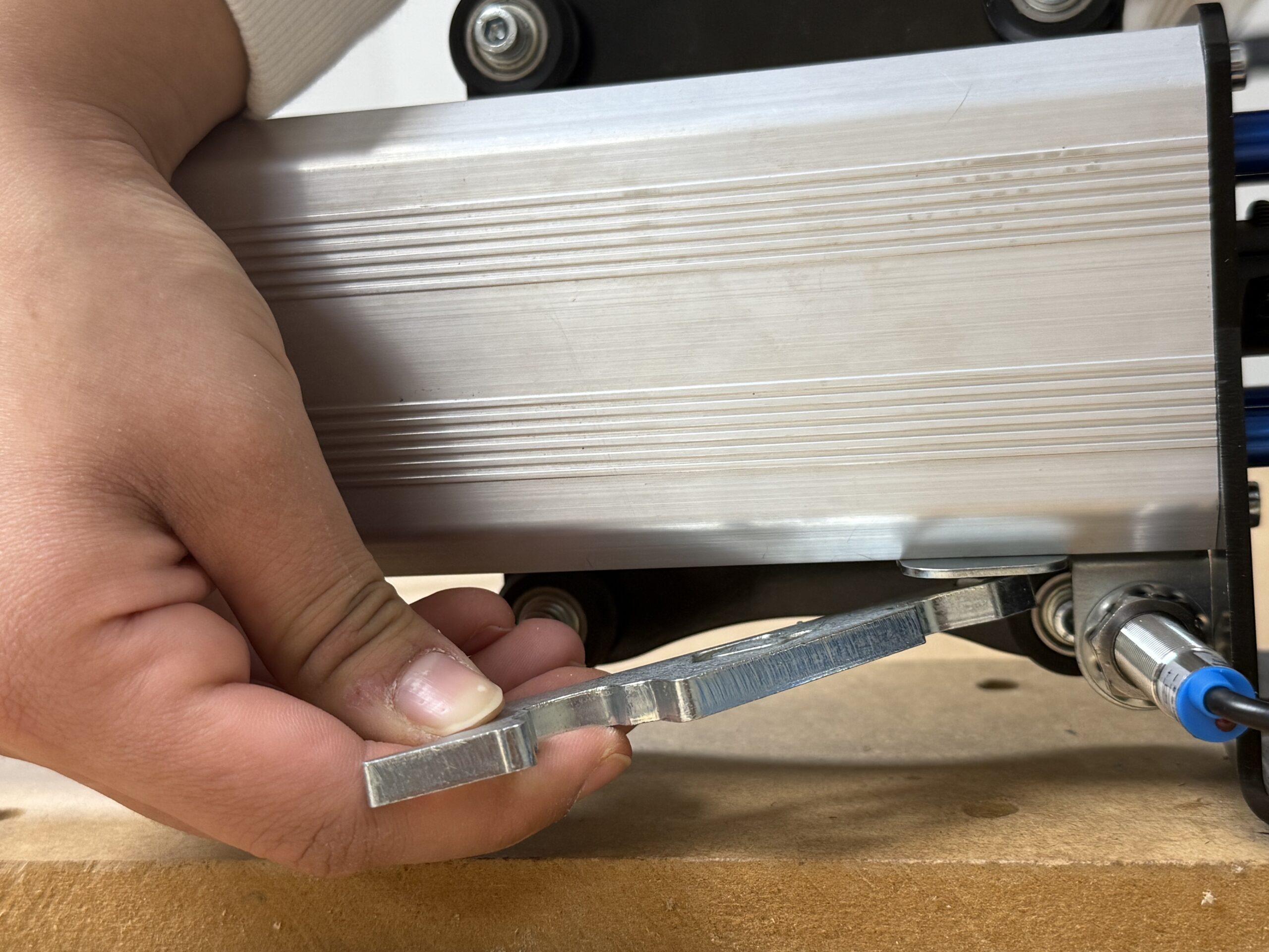
Slide the bracket onto the 10mm M5 screw until it bottoms out, then tighten down the screw, while holding the sensor.
Adjust the sensors so that they stick out slightly, allowing it to trigger the sensor on the wheels, without hitting them. You may need to adjust and test this step out to ensure you are not hitting, but are getting a positive signal each time the y-axis sensors are triggered.
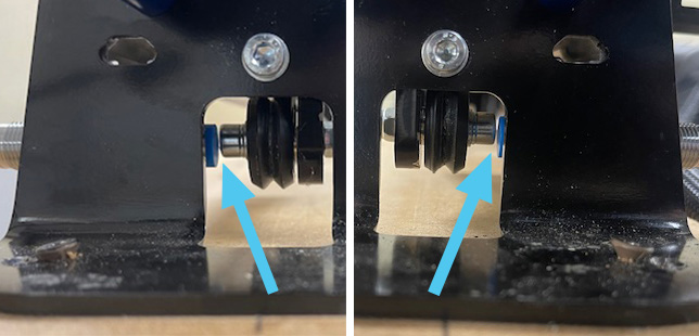
Repeat this step for both ends of the Y-axis (Right and Left).
Wiring
Now that we have all 4 motors mounted and the inductive sensors re-arranged, let’s move our attention to getting our wires organized. We will be replacing the drag chain that goes along the left Y-axis with a larger one & installing some 3D printed supports.
Drag Chain & Wires
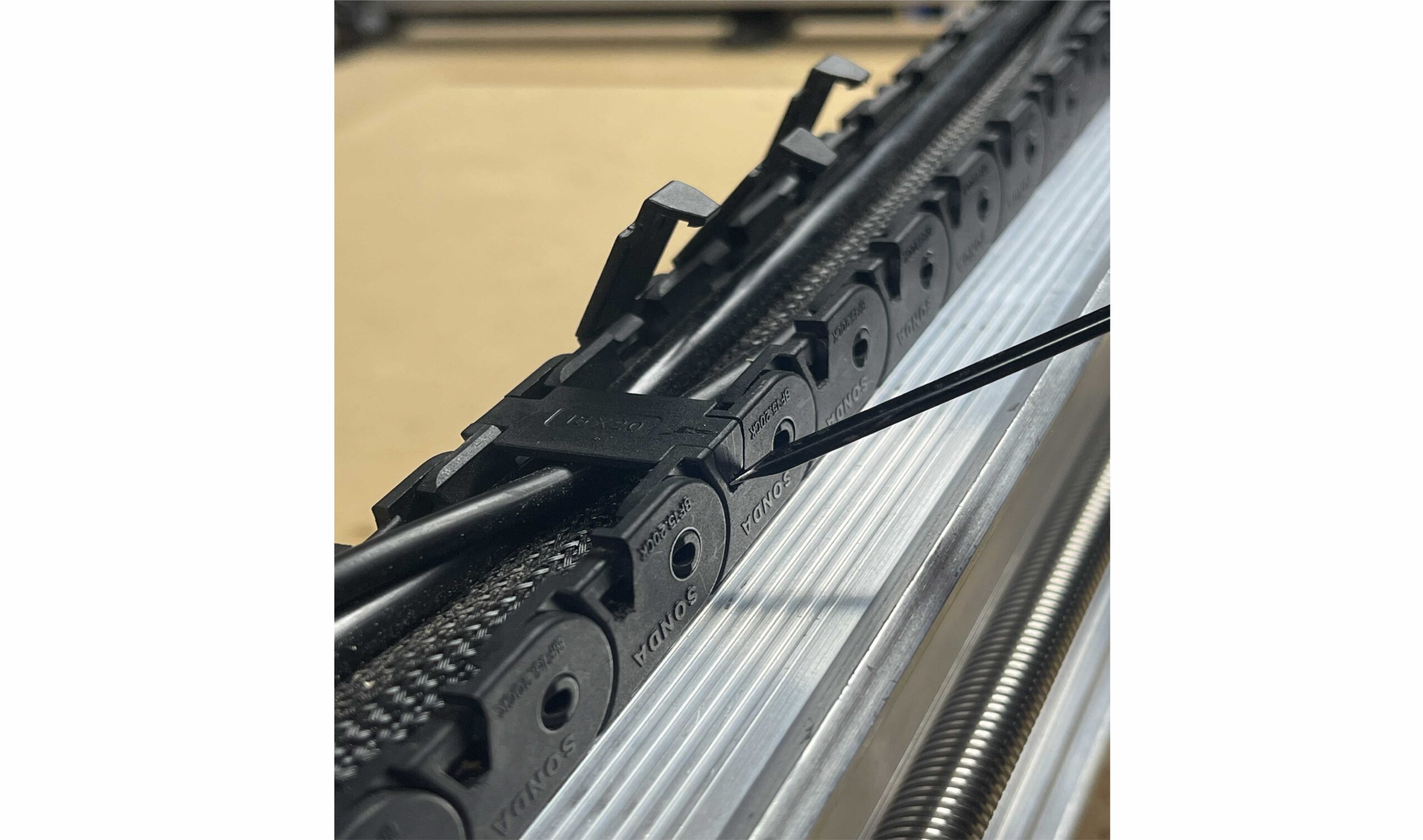
If you have not yet opened all of the tabs in both drag chains, do so at this time. You can slip a small flat head screw driver under each tab to pop them open. One side of each tab has a hinge (Don’t remove this side) and a catch. Make sure you unclip them on the catch side, not the hinge side. We will be replacing the Y-axis drag chain, and upgrading it to a larger size, so you can remove this drag chain entirely at this time.
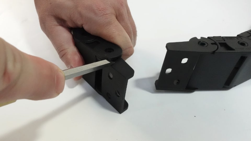
With the new, larger drag chain in hand, remove the end links, so we can install them separately, then have an easier time when it comes to reconnecting the drag chain. This can be done with a small flat head screwdriver.
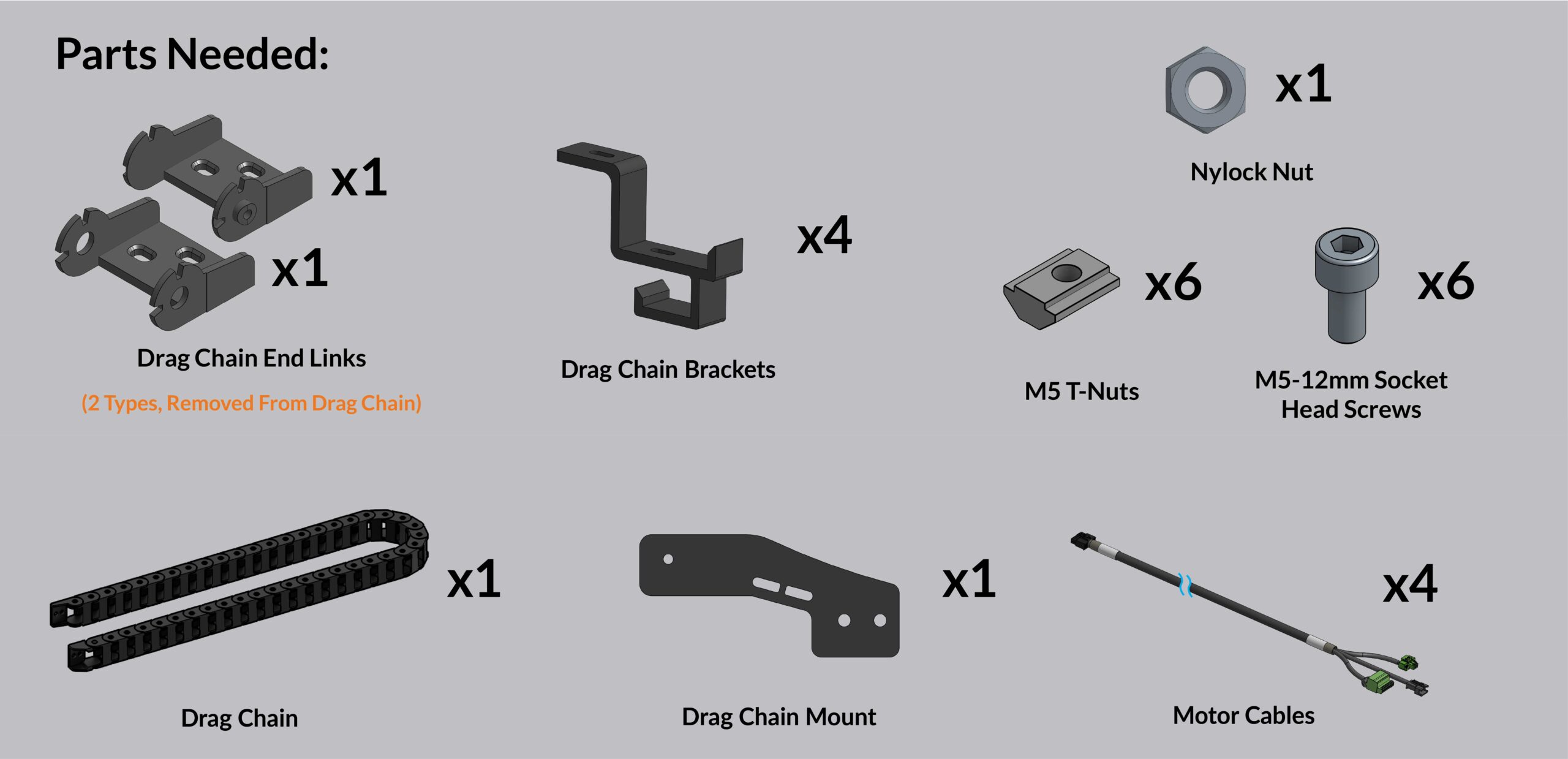
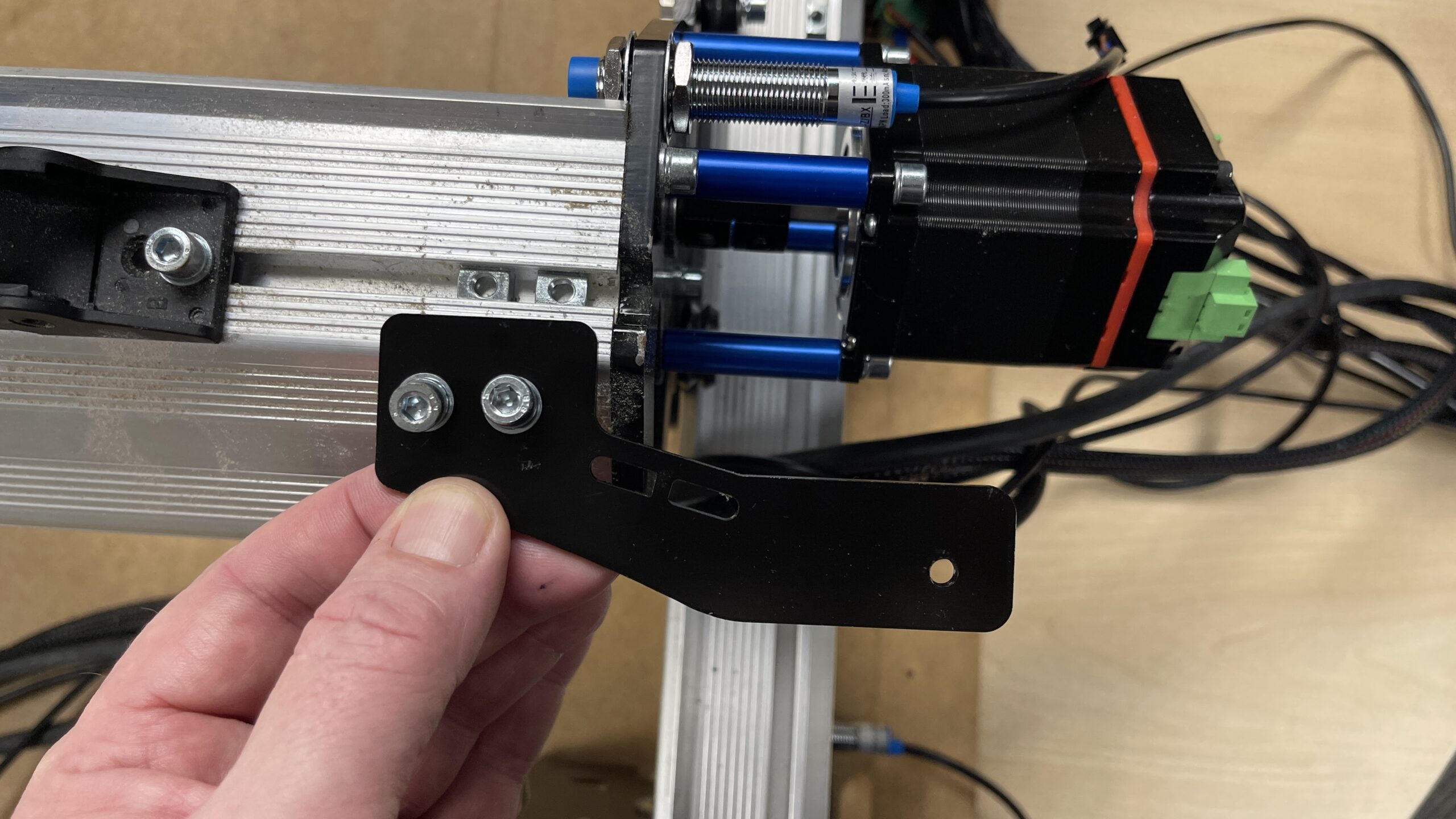
Grab the drag chain mount, 2 x M5 T-nuts and 2 x M5-12mm screws and attach the new black drag chain mount to replace where you old silver one was. You can re-use your M5 T-nuts in this step if you wish.
Now you can use another M5-12mm screw to secure the drag chain end link that has open ends. This hole is threaded, so no need for a nut here.
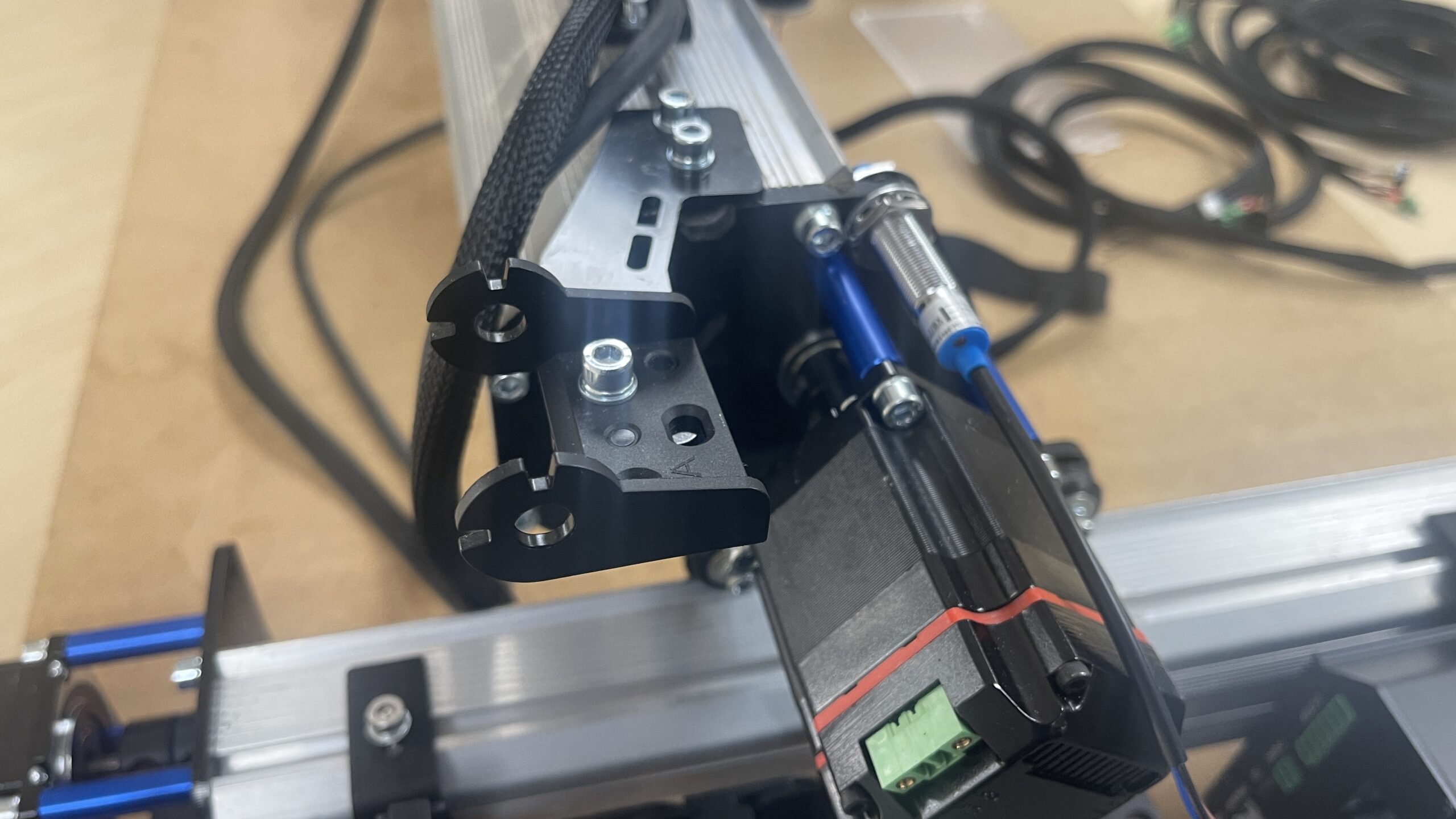
Moving to the Y-axis where the old drag chain was, move to the back and slide 4 M5 T-nuts into the rail. We will be using these to support the 4 drag chain brackets. Place a washer down, then an M5-12mm screw will hold down the bracket. Space them out evenly, using fewer if you have a smaller footprint.
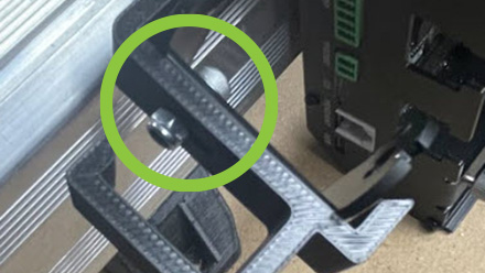
Now we can attach the final drag chain end to the last drag chain bracket with an M5-12mm screw and the nylock nut.
One tip that can help out in this step is to put the drag chain end on before you put the bracket onto the rail as pictured below.
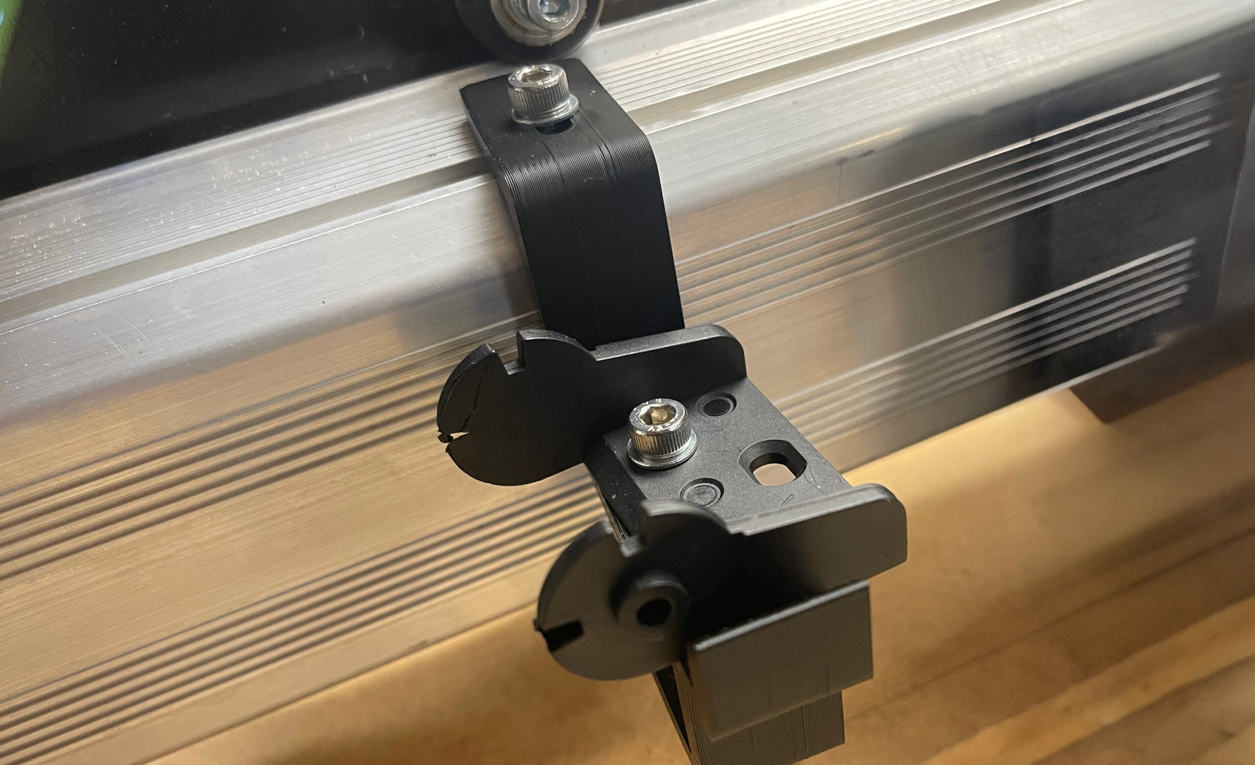
Slide the bracket into place and tighten down the M5-12mm screw.
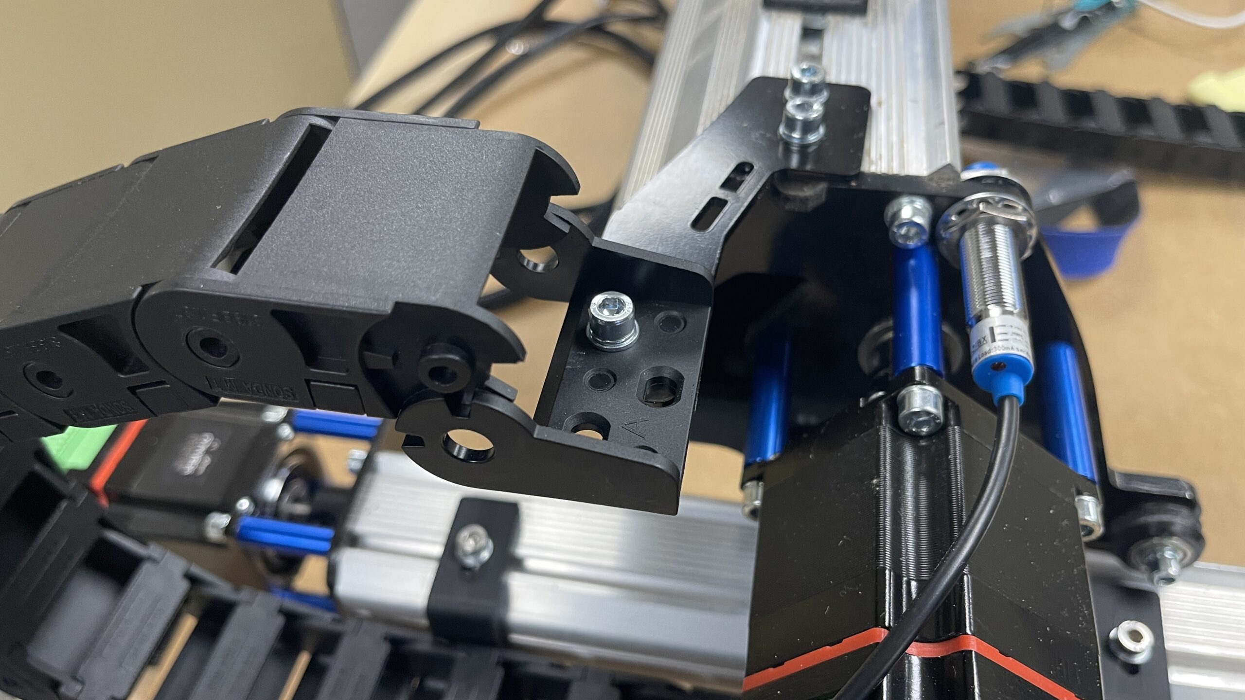
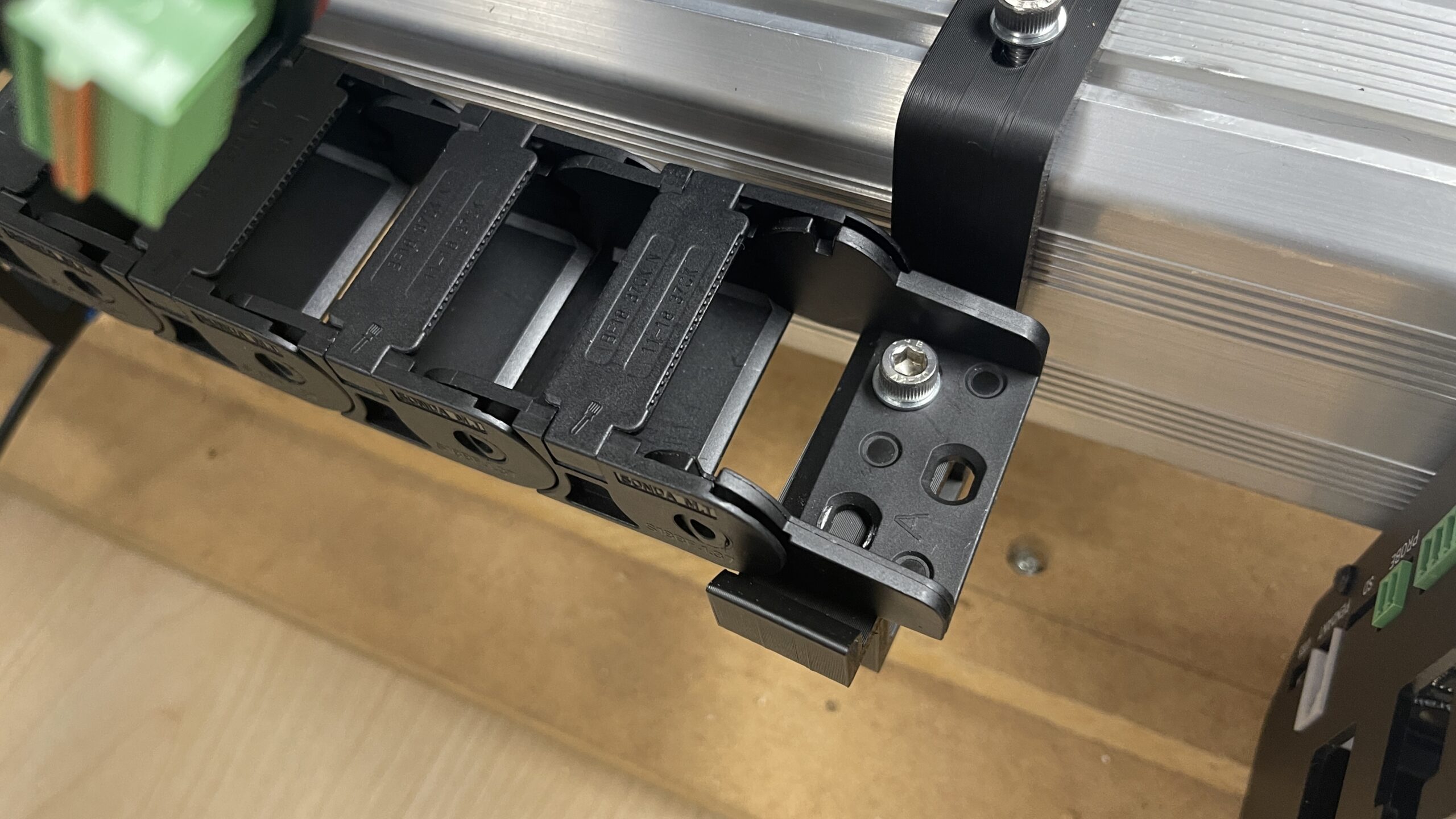
Clip the drag chain onto each drag chain clip.
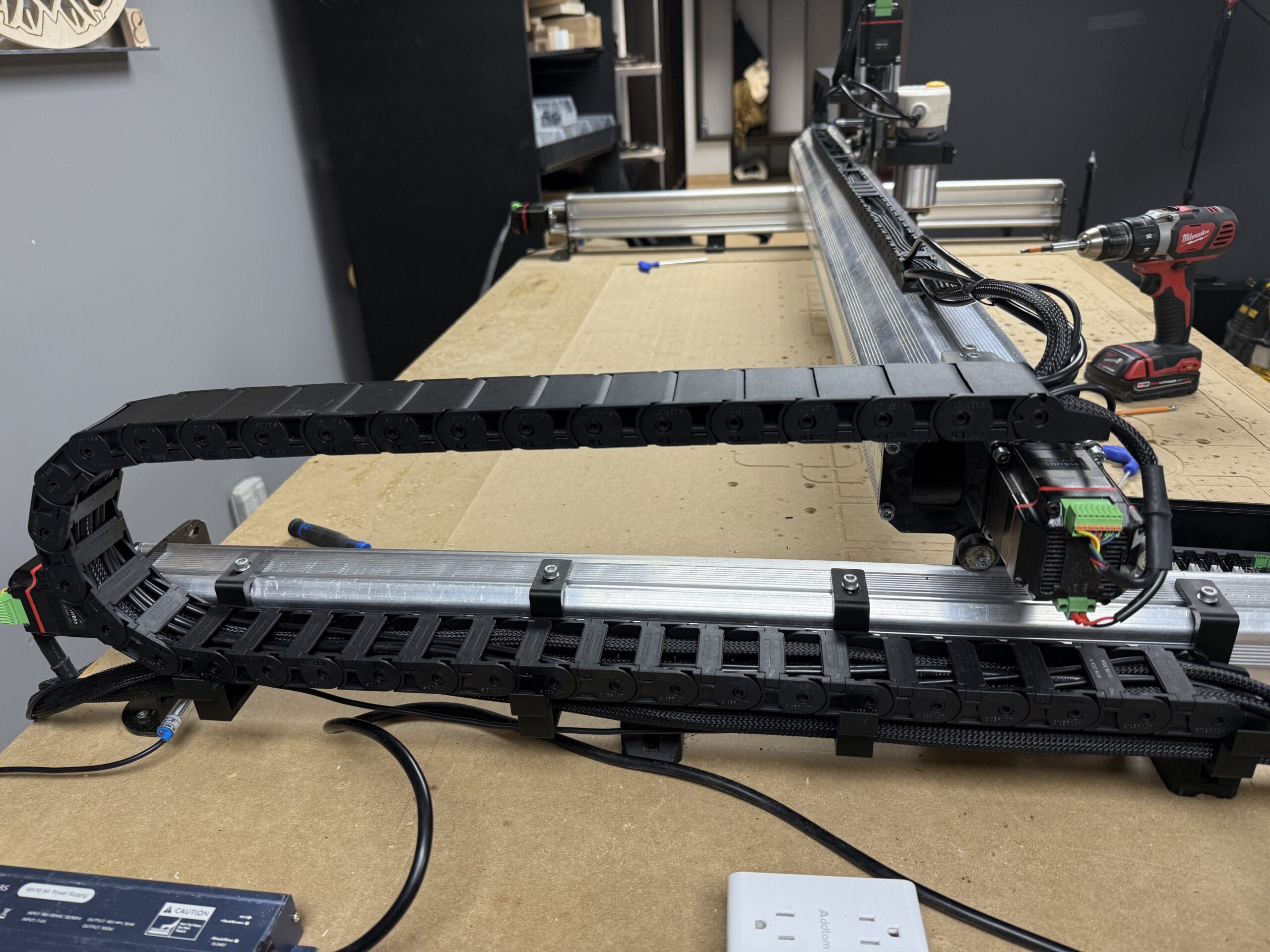
In this final setup image above, you can see the drag chain in place, with the wires all tucked in and all the tabs have been closed. Ensure you have enough slack left in the cables to enable the ends to reach both the motor connections and the connections on the SLB LITE.
When looking at your motor cables, you will notice each one is labelled with the corresponding axis it goes to. Let’s begin with the X-axis motor cable.
The motor cables have 3 plugs to attach on each end. The two green plugs are for your new motor, and the middle black one is for your limit switch/inductive sensor. No more individual cables, we’ve combined them all together!
Plug in the green motor power and motor signal connectors. Be aware that your motors may have an extra set of green connectors, already in place. You can remove these for safekeeping, as the wires all have the connectors already!
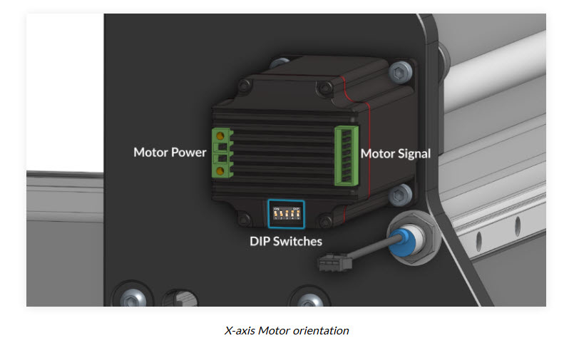
Now clip the black limit switch sensors together.
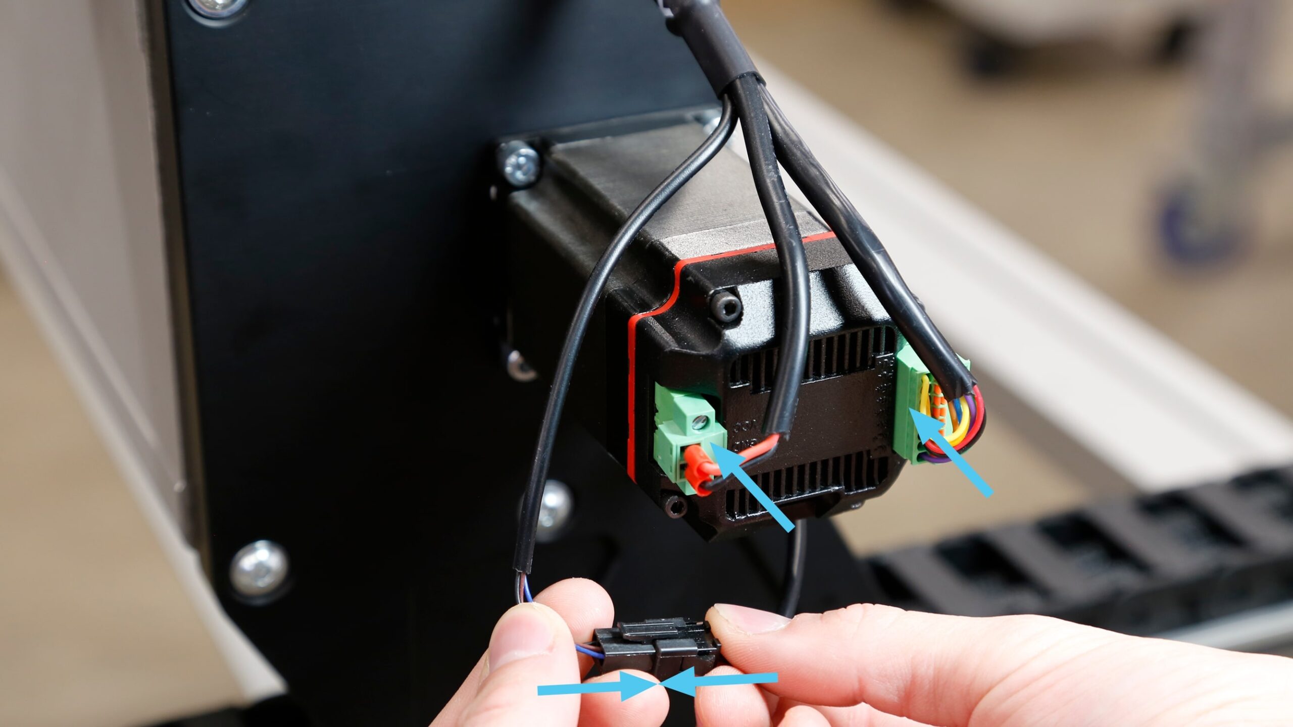
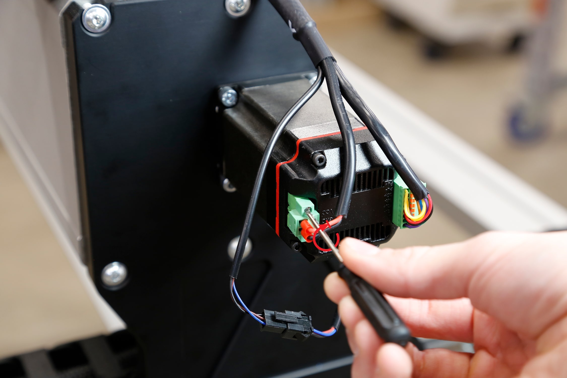
Once the power has been plugged in, tighten the screws down on the power plug with a small flathead screwdriver.
Motor Covers
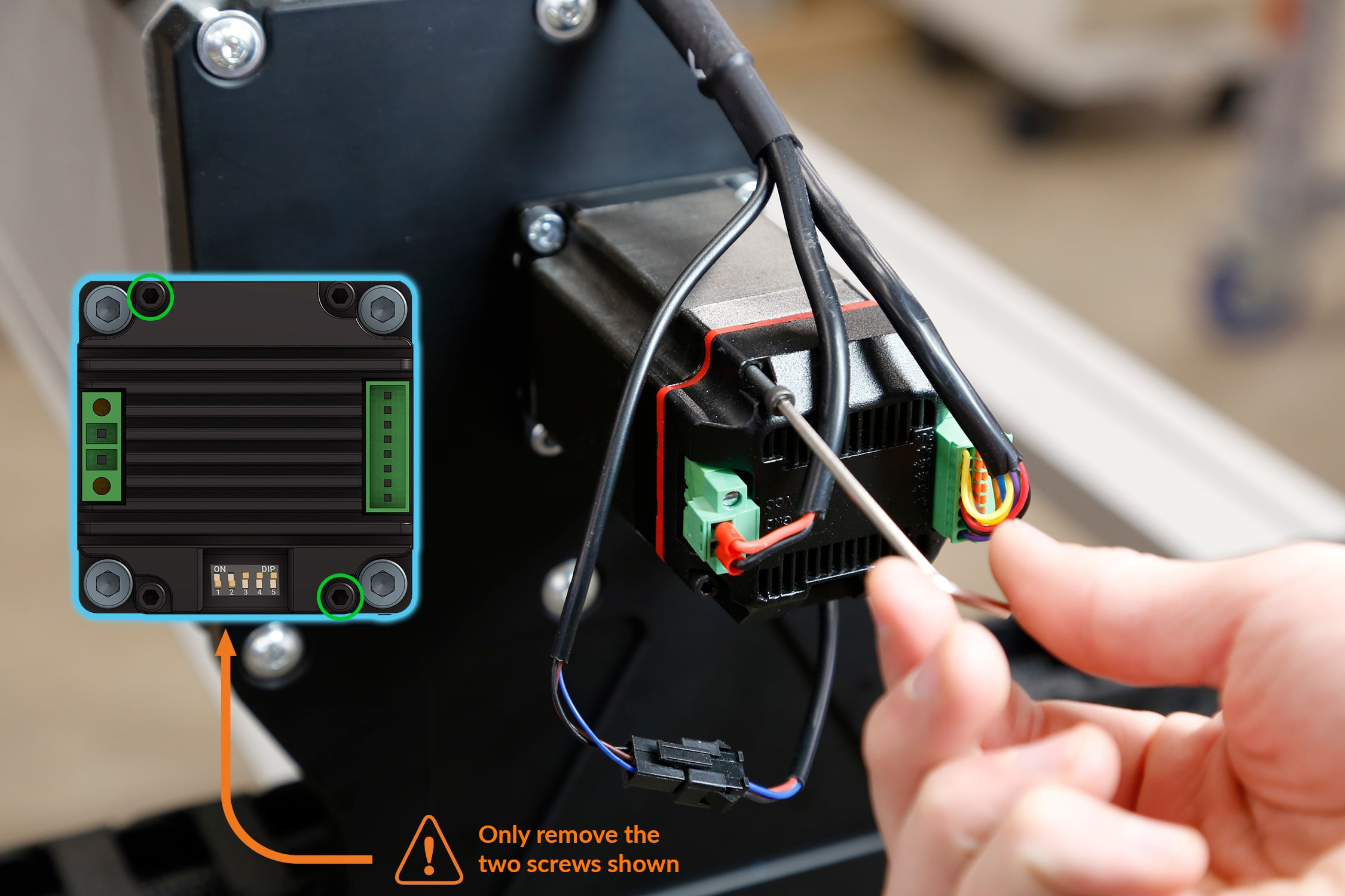
Your kit has included motor covers, to protect your motors from bumps or accidental unplugs. Remove the top-left and bottom-right M3 screws from the X-axis motor using the 2.5mm Allen-key provided.
Install the motor cover onto the back of the motor using M3-40mm screws. Orient the motor cover so the wires exit upwards.
Note: Install the motor cover gently to avoid damaging the wires attached to the connectors.
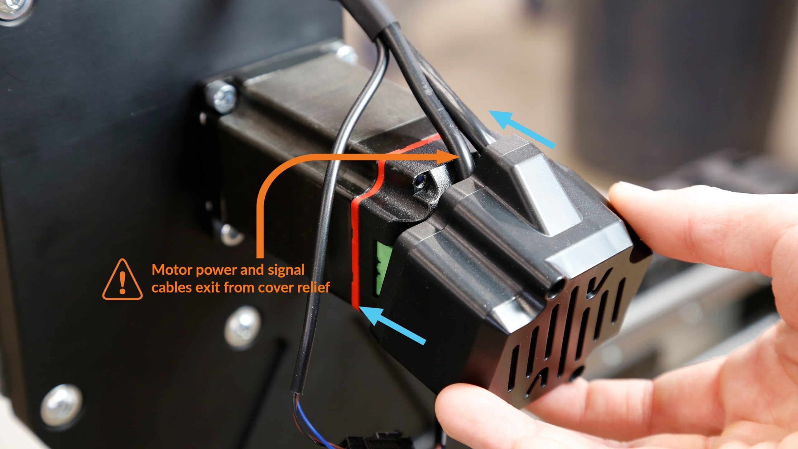
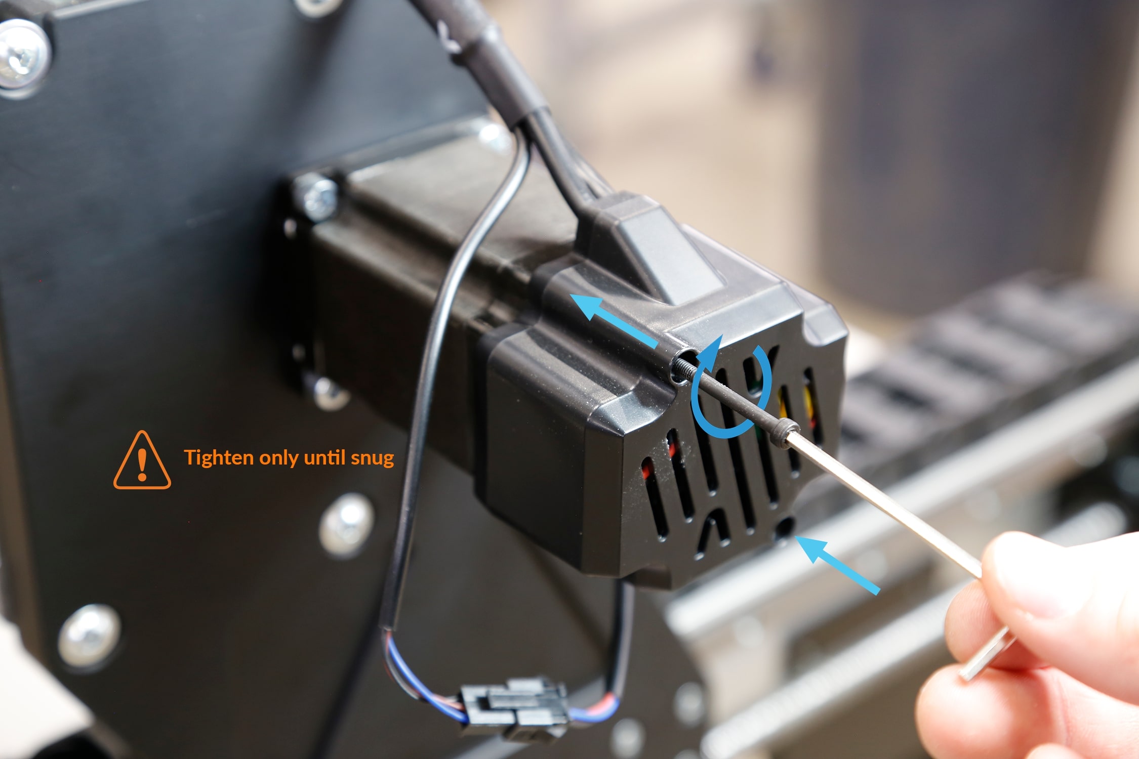
Repeat the previous steps for the Z, Y1 and Y2 motors.
SLB LITE
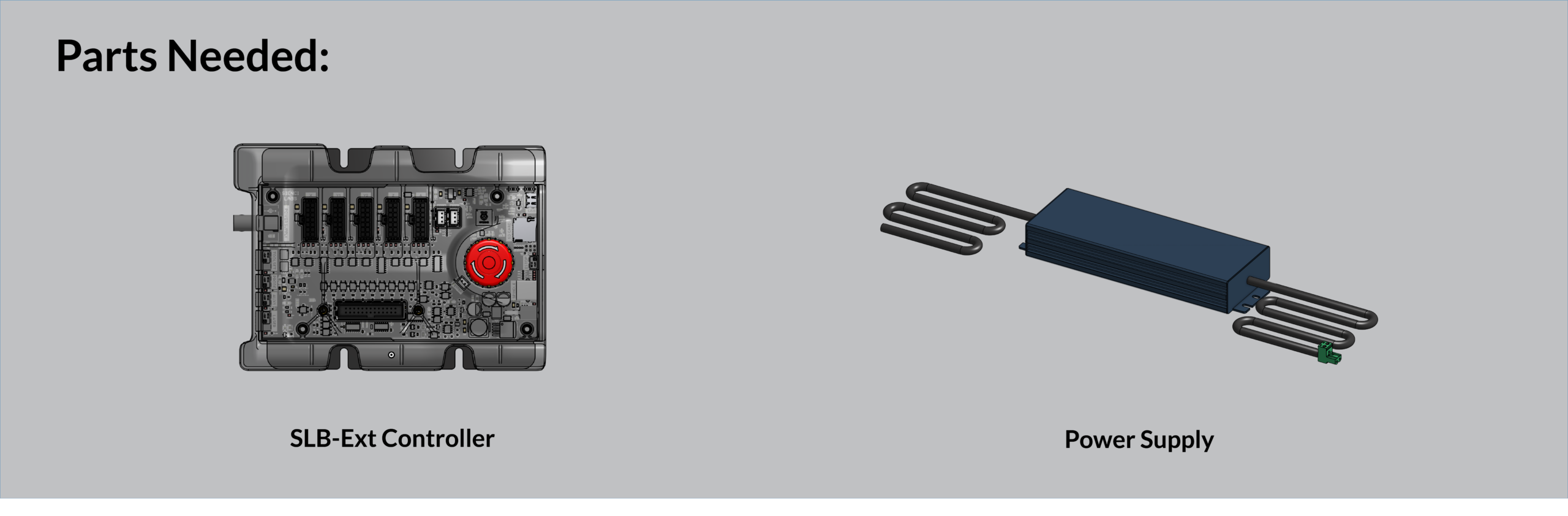
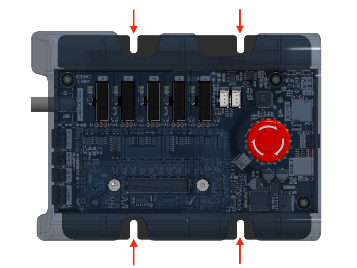
Mount the board to the wasteboard on the front, left corner. Grab your 4 wood screws, and secure the board using the indicated slots.
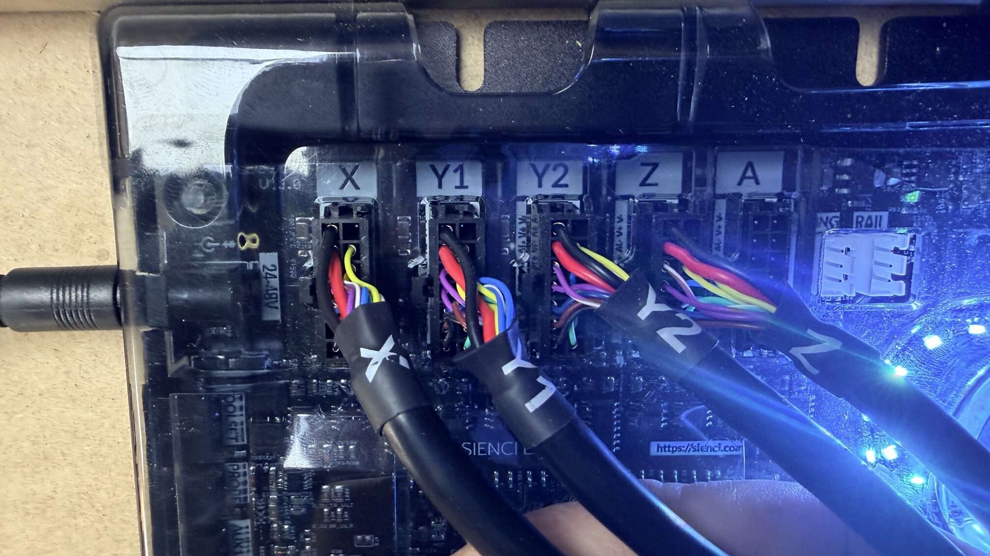
Now with the SLB LITE secure, let’s plug everything in! Grab your motor cables and plug them into the matching letters on the board.
Plug your power in on the left side of the board, and your USB on the right side.
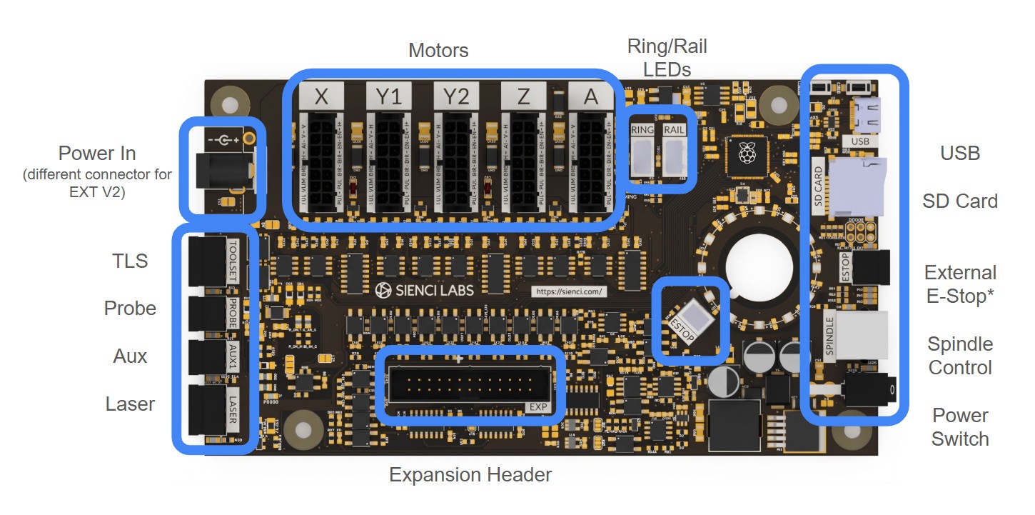
You can now flip the ON/OFF switch to power up your new board!
Software Changes
Once your setup is complete and everything is secure and plugged into the SLB LITE, we will need to adjust a couple software settings:
- the motor speed in your sending software
- the direction of homing (We are now going to the back left corner by default)
- enable homing on startup (Turning on both Soft and Hard limits)
You can tweak these settings manually, or, you can use our Macro instead! Simply download this macro and run it in gSender, and your settings will automatically update. You can click on the link below to go to a google folder and download the file (lmk2_clsm_macro_v1.json).
Closed Loop Stepper Motor Macro
If you are new to having limit switches, and are unfamiliar with soft and hard limits, check out our article on Limit Switches
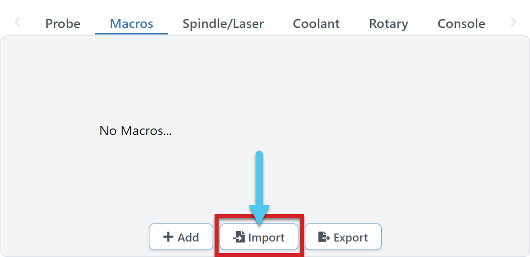
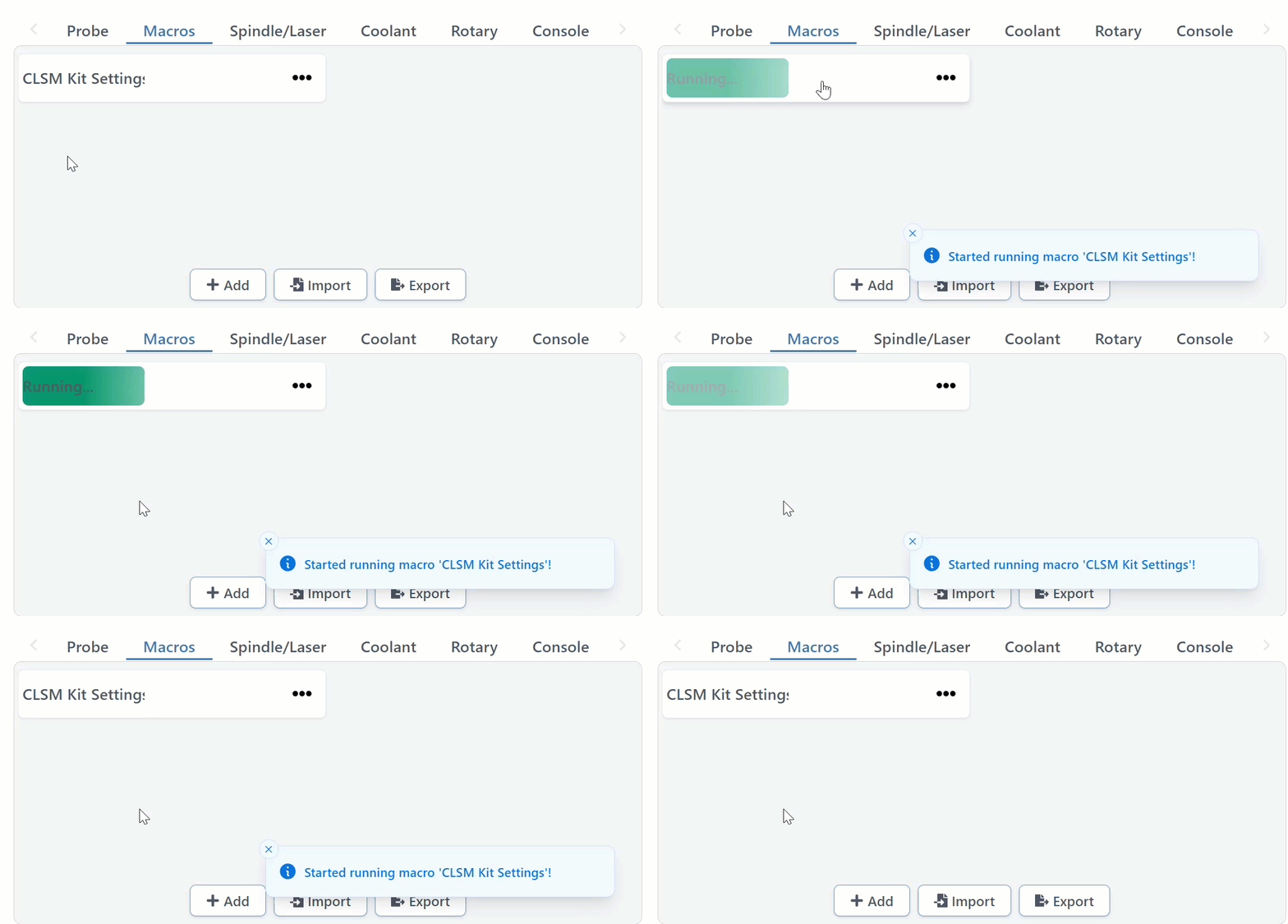
Once you have the file, load up gSender, and go to the Macro section on the Carve tab. Here you can import the new macro.
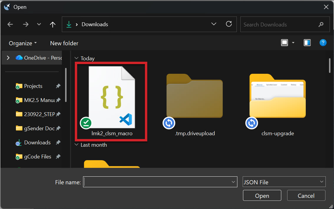
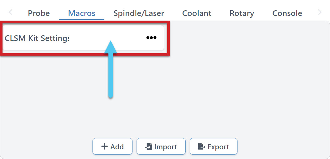
Once the macro is loaded into gSender, click on it to run.
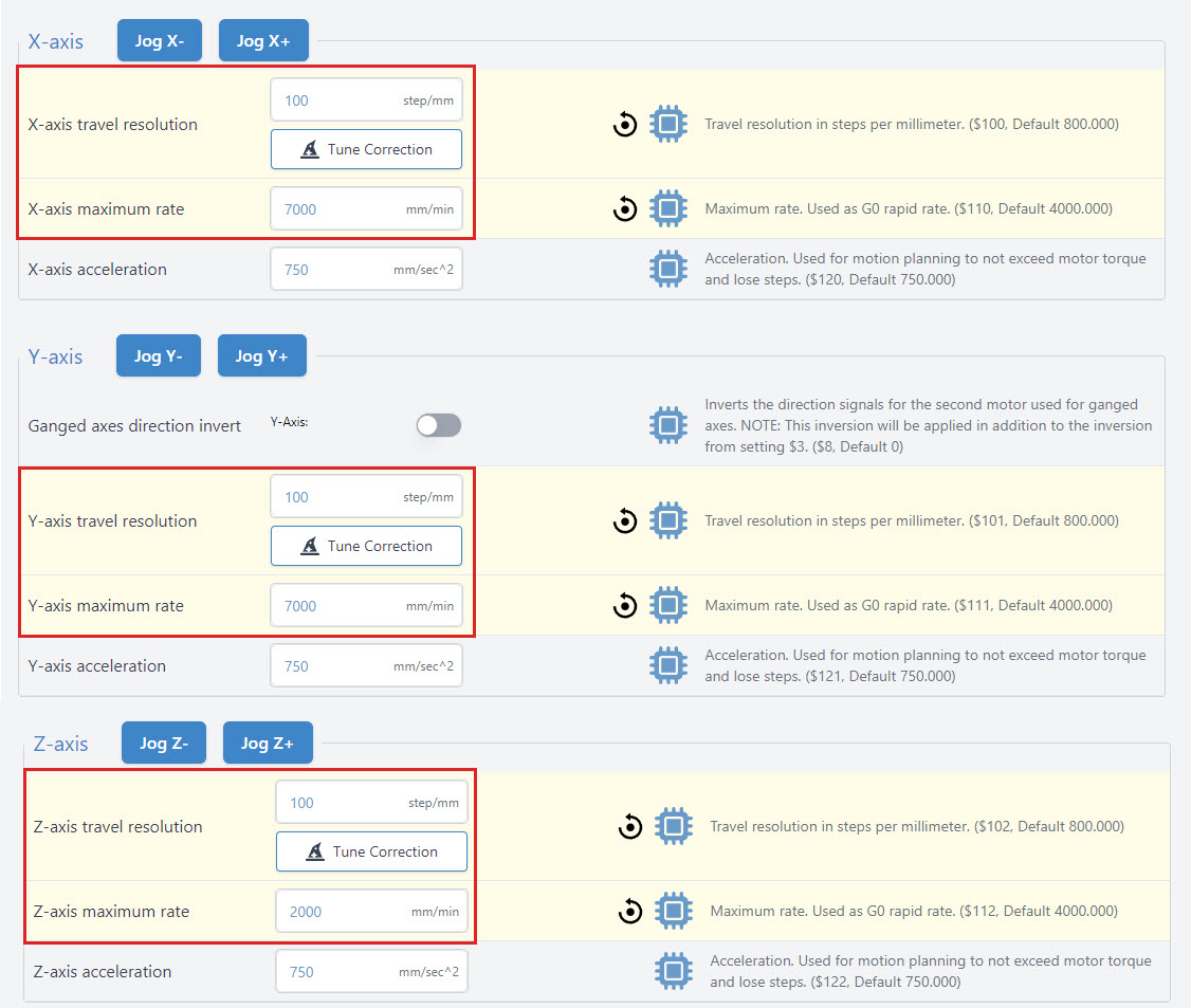
The macro will automatically update your motor settings! You can double check that they are correct by matching the configuration shown below.
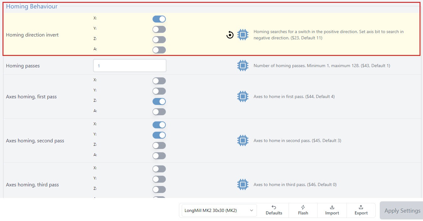
The Macro will also flip your homing direction for the Y-axis, by turning it off. Here you can see that only X is toggled on. This will send the machine to the back when homing, where your new sensors are installed!
Congrats! You have now completed the installation and setup of your new Closed Loop Stepper Motor Kit.
Starting Up
A safety feature of the SLB-LITE that is new to LongBoard or SLB users, is that the E-Stop will need to be cycled (depressed and released) before unlocking the system, or movement will be prevented.
Generally a good workflow is to open gSender and:
- Depress the E-Stop (Press it so it’s down)
- Power on the SLB LITE
- Release the E-Stop (Turn counterclockwise to release)
- Connect to gSender
- Unlock gSender (Click the lock icon at the top of the screen)
- Proceed as normal
Remember to home each time you startup and connect to the machine. You can tweak your Homing Cycle settings to require this on startup too if you wish.
Learn more about using your Limit Switches.
Go carve something cool friend!
Open Source
Here you can find the schematics/drawings that are available for download.
Still here and wondering why you have an extra ‘black plate’ that hasn’t been mentioned at all? It’s a part that is used for another machine, not for this kit specifically. Go ahead and carve something cool on it. Cheers!