
This page acts as an easy reference for all past documentation written before gSender version 1.5.0. Similar to the current docs, it’ll go over Setup and Layout items first, then introduce Basics Features for day-to-day use before progressing to more Advanced Features such as shortcuts, macros, calibration tools, spindles, lasers, and more. If your’re having some issues with gSender, definitely visit the Troubleshooting section to see fixes to common issues or see how you can get in touch with us. Remember, you can always quickly navigate the page by clicking the headings in the ‘Page Contents’.
gSender Updates
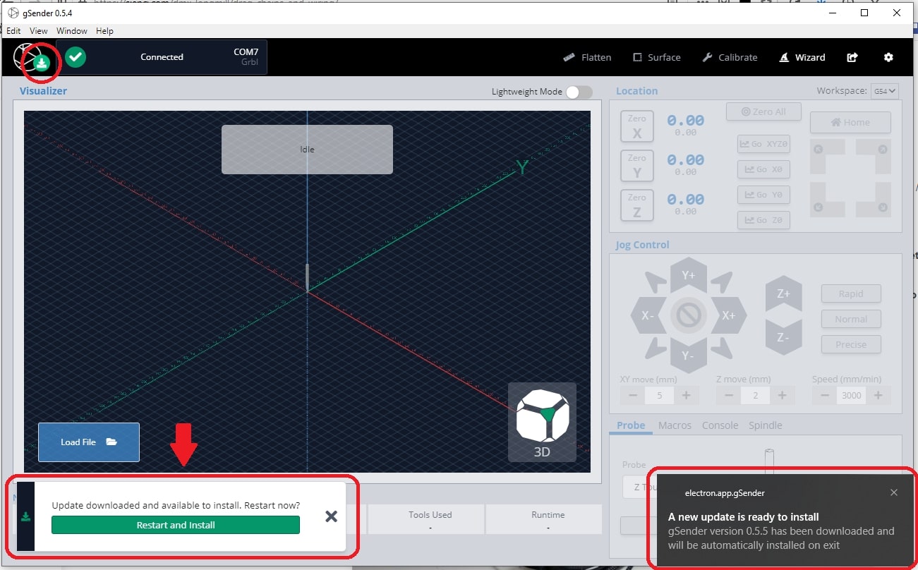
gSender will notify you when new updates are available, allowing you to download them quickly and get running with the latest version. If you don’t see these notifications, your system might not support it or your computer Firewall may be blocking them but you should still be able to download the newest version manually and install it over-top of the old version.
gSender updates always have the chance of encountering quirks, so if you have an important carve coming up or are just satisfied with your current setup then we’d typically recommend holding off until updating will be less ‘mission-critical’. If you update accidentally and want to go back, you can also always downgrade.
If you upgrade to a new version, or downgrade to an older version, and gSender won’t open or run (blank screen):
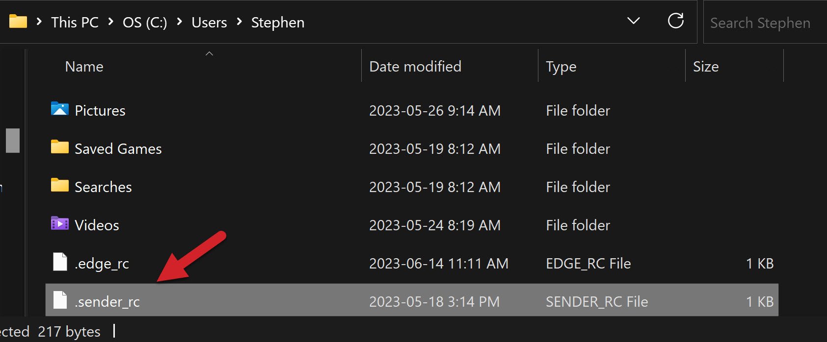
You’ll want to find a file called “.sender_rc” and rename it so gSender can generate a new version without errors. Sometimes you might also want to delete the “.sienci-sessions” folder too.
- For Windows: the file can usually be found on your hard drive, at: C:/users/{your username}/.sender_rc. Rename it to whatever you like, like “.sender_rc_old“, then try to reinstall gSender again.

- For Mac/Linux: the file is in the home directory as a hidden file. You can either:
- In Finder go to Go ➜ Computer ➜ Drive ➜ Users ➜ {your username} then un-hide the “.sender_rc” file by pressing
CMD + Shift + .keys. Rename it to whatever you like, like “.sender_rc_old“, then try to reinstall gSender again. - Go into the Mac/Linux console and enter the command
mv ~/.sender_rc ~/.sender_rc_old. You’ll be able to double check the renaming was successful by sendingls -al | grep senderin the console, where if you only see.sender_rc_old, you have successfully remanded and are ready to try to reinstall gSender.
- In Finder go to Go ➜ Computer ➜ Drive ➜ Users ➜ {your username} then un-hide the “.sender_rc” file by pressing
- If this solves your problem, you’ll still be able to recover your old Start/Stop events and macros from the renamed file; just open it in a text editor and copy the macros you want to save so you can paste them back into gSender.
Older Versions
If you just updated gSender and are finding that it’s not working for you, downgrading again is always available:
- If you go here: https://github.com/Sienci-Labs/gsender/releases, the newest version will always be at the top and shown in bold text like “v1.4.3” for example
- Scroll down to find older versions and choose the next version down or whatever version number you remember using
- Once you’re at the version you want, scroll down to find “Assets” and click the text to open the list of downloads
- Find the right one for you, Windows is “.exe”, Mac is “.dmg”, etc. and click the file name to start downloading it. Once it’s downloaded, you can install it over your current gSender version and continue from there
Anonymous Information
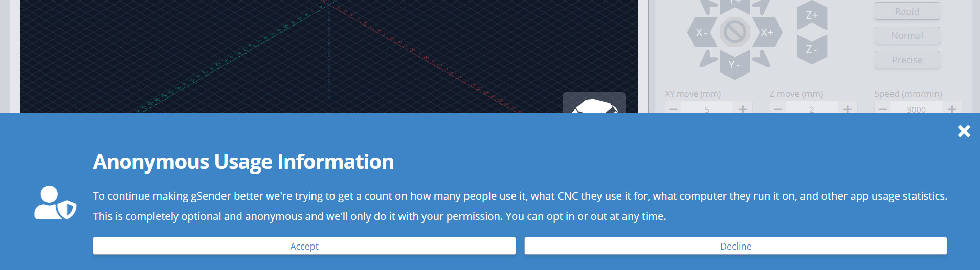
When you open up gSender, you’ll notice a prompt regarding ‘Anonymous usage information’. This is just to ask if you’d be fine with us knowing things like what CNC you use it for, what computer you run it on, and other information about how you use the app. You can imagine that if we know certain features are widely used or certain errors are constantly encountered, that can be very helpful to understand how we can improve the app or its documentation. This is completely optional and anonymous, we only do it with your permission and it can be turned off at any time in the settings menu.
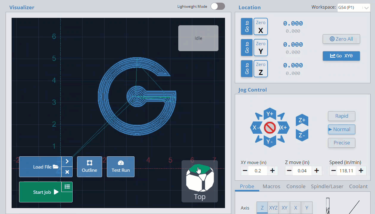
Layout
Before starting to use gSender, let’s briefly cover the way its functions are laid out so that you’ll know where to find things moving forward. The program only has one main screen, it’s into three major sections:
- The top toolbar has all the things you’ll only use occasionally. This includes machine connection on the left side (boxed in red) and gSender’s Settings, Help, and other additional ‘Tools’ on the right (boxed in blue).
- The left-side control (boxed in green) has all the functions you need for loading, monitoring, and controlling g-code files and cutting jobs
- The right-side control (boxed in purple) has all the functions you need to manually control your CNC when jobs aren’t running. This includes jogging, zero setting, homing, probing, running macros, manual laser / spindle control, and more.
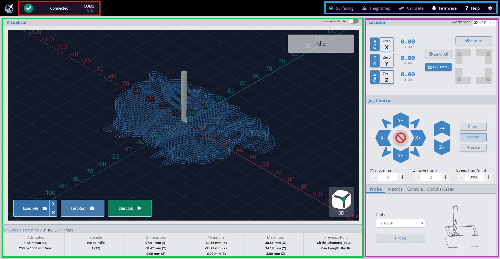
We’ve built gSender’s layout around these primary boxed sections so that you can have all of the CNC functionality most hobbyists need on one screen without getting confused about what each button does. If you’re doing anything during a job it’ll be on the left side, if you’re doing anything outside a job it’ll likely be on the right, and if you want greater customization or functionality it’ll be found in the tools or settings.
Another of gSender’s Design Principals is colouring. It can be scary to have an assortment of buttons in front of you and not know what they’re going to do. This is why we made every button on the right-side control that moves the CNC, blue. This means you shouldn’t ever find yourself startled when the machine moves unexpectedly since the colour will help to communicate whether it’s a ‘machine moving’ button or not.
Configuration
Let’s do some configuration before connecting up to your CNC. Click the ‘gear’ at the far right of the toolbar to bring up the program settings. Some things you’ll likely want to configure would be:
- General Settings
- Baud rate needed for your particular CNC. Baud rate is setup for the LongMill by default.
- Machine Profile
- Preferred Units
- Reverse workspace (flips the left and right-side controls if you prefer)
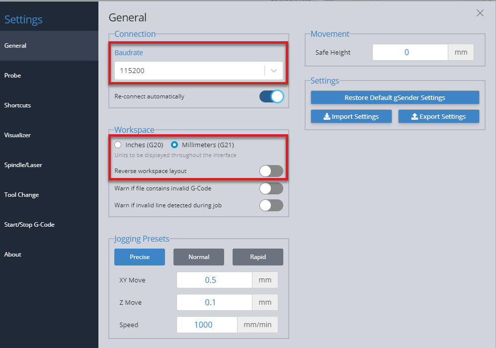
- Visualizer Settings
- Set to light theme if you prefer
- Set to light theme if you prefer
Machine Profiles
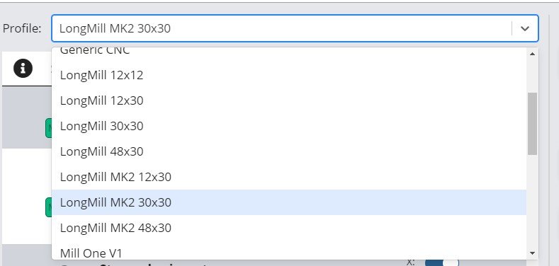
If you’re planning to make any firmware modifications, gSenders Firmware tool at the top right of the screen defaults to displaying the “LongMill MK2 30×30” profile. If that’s not your machine, then beside the word “Profile”, select your machine from the dropdown menu (if it’s not listed then select “Generic CNC”).
For instance most LongMills ship with LongMill MK2 30×30 firmware pre-installed so it matches gSender, but if you have any other machines from Sienci Labs then you’ll need to match it up (for example: 12×30 or 48×30 MK2, any sized MK1, AltMill, etc.). For supported machines, once you’ve made this change you might want to ‘Restore Defaults’ to ensure your machine has all the most up-to-date settings.
Please Note: If your Z-axis is working in the opposite direction than expected, confirm you have the correct profile. MK2 users must choose either LongMill MK2 12×30, LongMill MK2 30×30, or LongMill MK2 48×30. You can find instructions on how to flash firmware here: https://resources.sienci.com/view/lmk2-grbl-firmware/
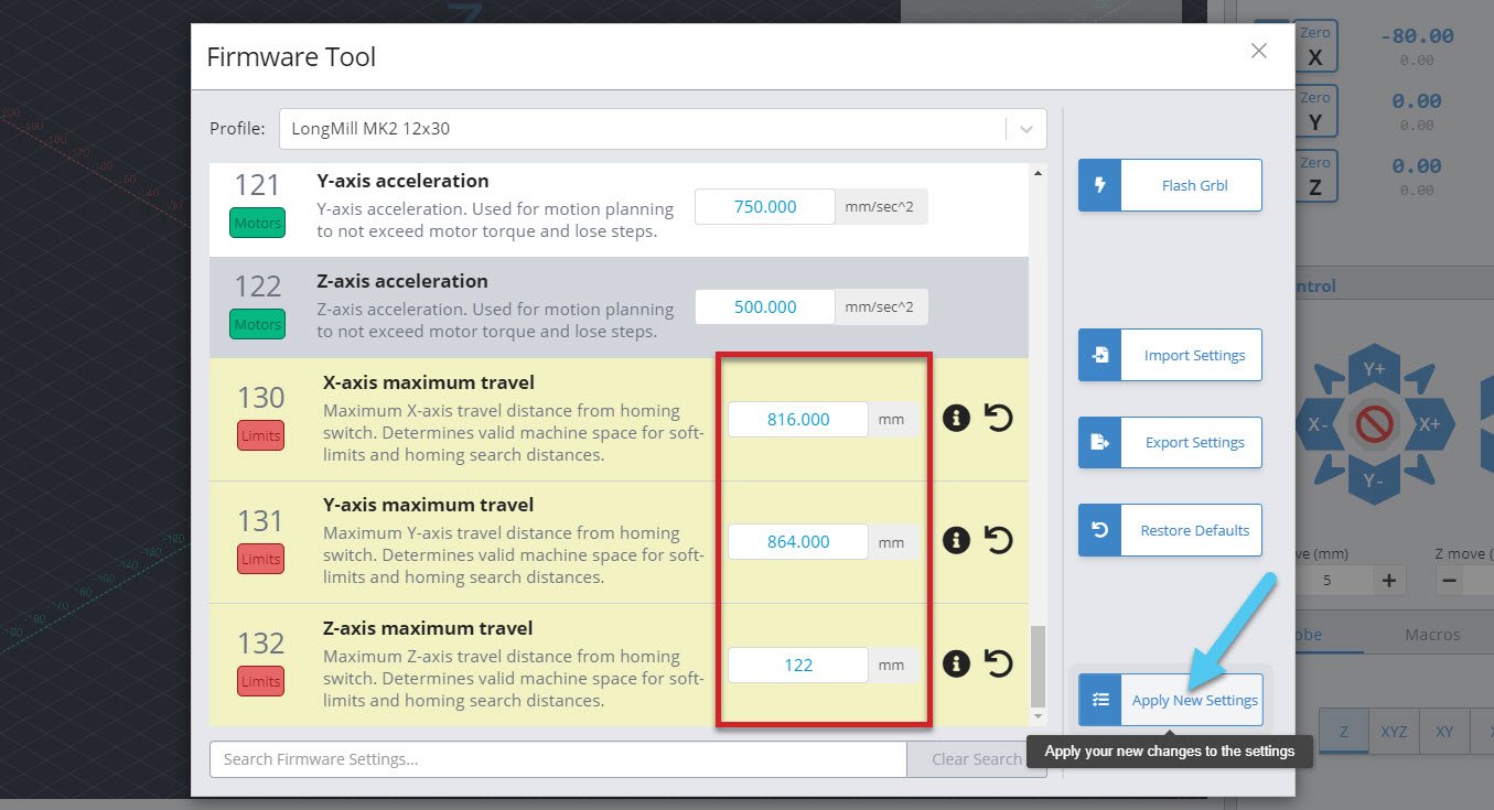
If you’re running into an issue where the size isn’t correct when using Soft Limits for example, get the size from your manufacturer or their resources and you should find that the changes will be straightforward to make through the ‘Firmware tool’ within gSender. Simply apply your new measurements to the X-axis, Y-axis and Z-axis maximum travel fields. Then hit the apply changes button.
Running Longer Jobs (optional)
Windows computers can tend to have their screens and USB ports ‘fall asleep’ even in the middle of running a long carving job. This can cause your intricate cuts to stop short and the job to fail. gSender tries to fight against this by keeping your computer awake (we use similar tactics to auto-clicker apps), but sometimes this still isn’t enough so you have to change your computer settings manually.
To keep the display on, you’ll want to click the Windows icon at the bottom left corner of your screen and start to type “control panel” to bring it up.
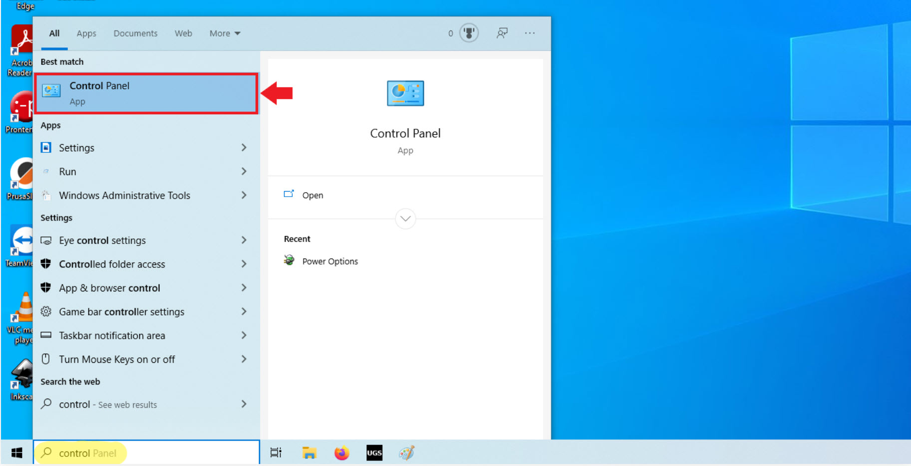
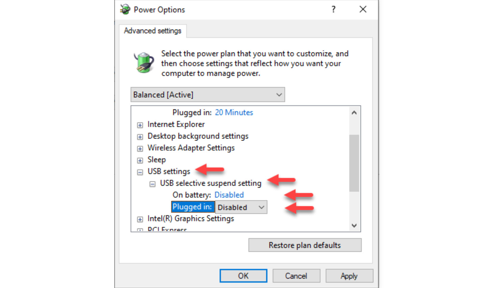
Once you’ve clicked to open it, go to Hardware and Sound then Power Options


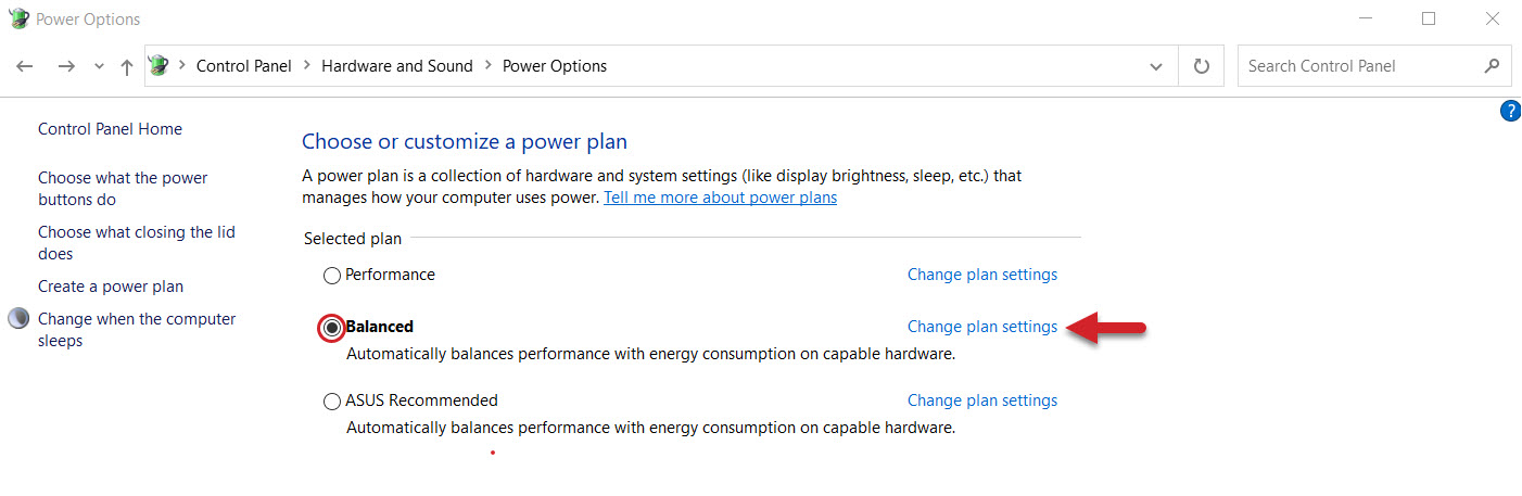
The plan that’s currently selected (circled in the picture) will be the one that you want to change. In this example we will be editing the Balanced plan. Click on the “Change plan settings” text (highlighted with an arrow).
Go to the second drop-down and set both ‘battery’ and ‘plugged in’ selection to Never, save the changes to ensure that your computer never dozes off on its own.
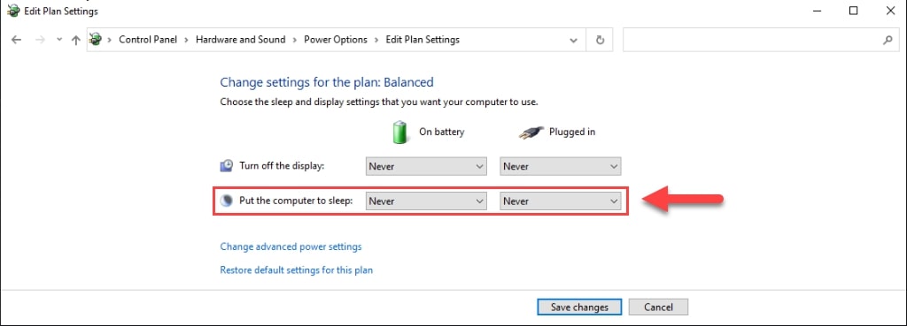
To keep the USB ports on, click Change advanced power settings
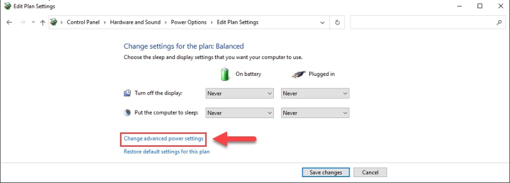
In the separate window that appears, you’ll want to Expand the USB Settings, then USB selective suspend setting, and finally change both the ‘battery’ and ‘plugged in’ settings for these drop-downs to ‘Disabled‘. Click OK to Apply these new settings.
After having done all of this, just be mindful now that sometimes a Windows update can remove these settings. If you have an update and want to be confident running your CNC, we’d recommend checking back on these settings to make sure they’re still set properly.
Starting Up
Here’s a great video that goes over much of how a g-code sender works in the context of gSender. See Kelly explain many of its uses and features:
When you double click the gSender icon to open up the program, it can take several extra seconds to load if you have Microsoft real time virus protection on your computer. This scan delay should only happen the first time you turn on your computer.
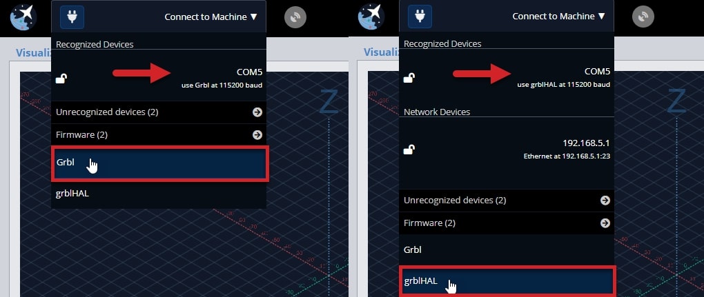
Connect to your CNC machine by hovering over ‘Connect to Machine’ at the top left corner. You’ll need to select the right firmware for your board, but just the first time you connect. Most hobby boards use “grbl” including our original LongBoard, but if you have the SLB or LongMill MK2.5, then you’ll want to select “grblHAL”. You’ll see these options in the dropdown where the selected one has white text.
Sometimes there’s more than one COM port available, so you may need to try both to see which one your machine is connected to. If you are seeing errors pop up or your machine isn’t acting correctly, ensure that you have selected the correct connection type.
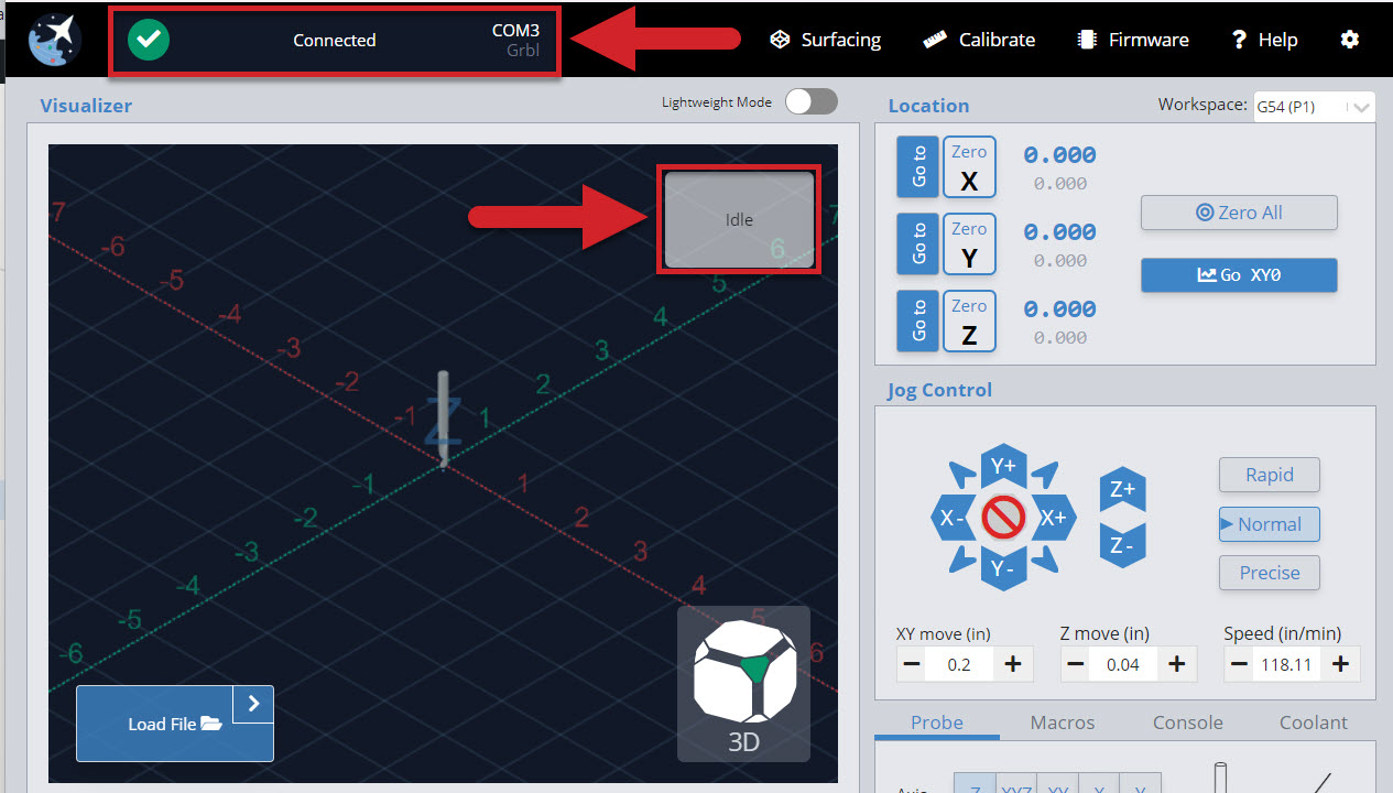
Once you have selected the COM port, your machine should be connected. This is confirmed when you see the plug icon turn green with a check mark. You should also see the status on the top right corner of the visualizer change to ‘Idle’, and the controls activate, allowing you to press them.
If you are not seeing those changes when you connect, please check the following:
- Arduino is securely attached to the LongBoard.
- Any other programs that can talk to the Arduino are closed (ex. Arduino IDE, Easel, UGS).
- See if you have other COM ports available, and try to connect to them.
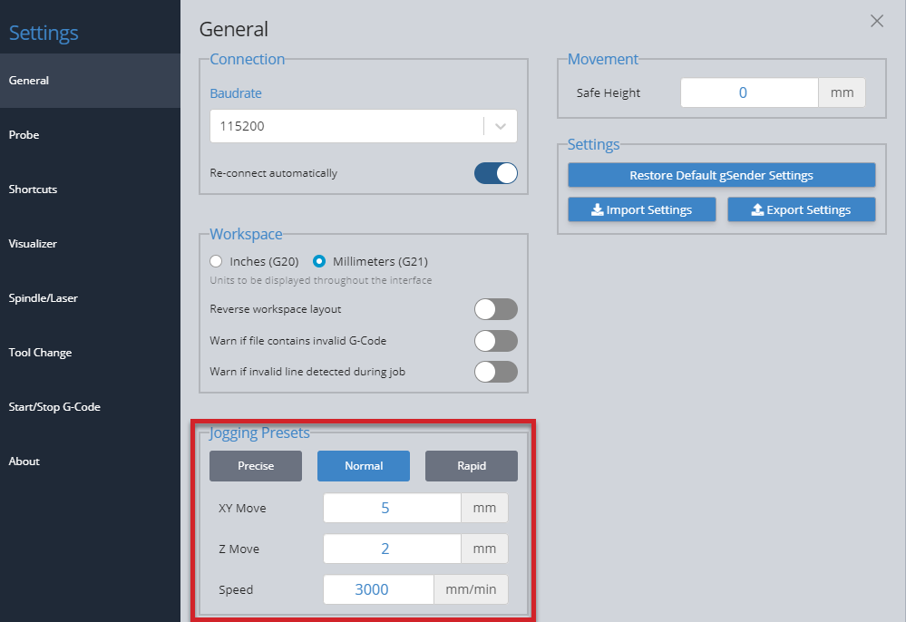
Jogging and Presets
You can move the machine by using the Jog Control, through the arrow buttons. Change the ‘XY move’ and ‘Z move’ to adjust the distance you travel per click. You can also change ‘Speed’, which determines how fast the machine will move when jogging.
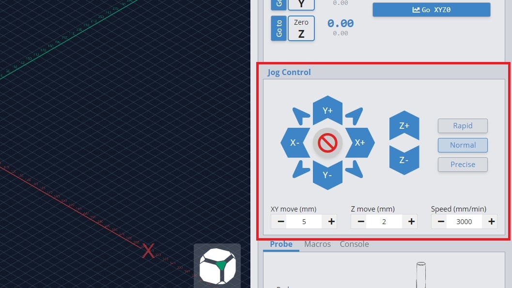
The ‘Rapid’, ‘Normal’, and ‘Precise’ buttons will allow you to toggle to different distance and speed values quickly. You can change these values by going to the settings and editing the ‘Jogging Presets’ in the ‘General’ section.
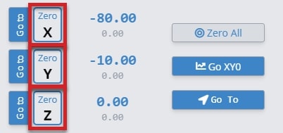
Set Zero and Go tos
Each g-code file or project will have a starting position that all other movements are referenced off of. This is the zero or origin. There are two ways to manually set your zero on gSender.
-
Set the zero for each axis one at a time using ‘Zero X’, ‘Zero Y’, and ‘Zero Z’ buttons
-
Set the zeros all at once using ‘Zero All’
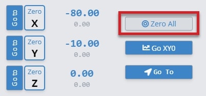
The large blue numbers tell you the current position of your machine. If you want to return to your zero position, you can press the ‘Go to’ for each individual axis and the large blue numbers will read “0.00” once it’s finished moving.
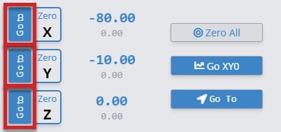
You can also use the ‘Go to XY0’ to return to the starting position in X and Y in one movement. ‘Go XY0’ will not move the z-axis to its zero.
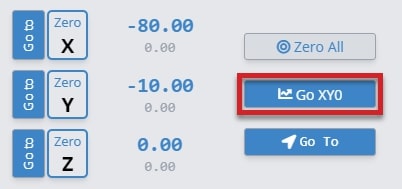
Note: if you’ve set up “Safe Height” in gSender, then the Z-axis will move up by that distance before moving the X or Y to make sure your machine doesn’t run into clamps or other materials.
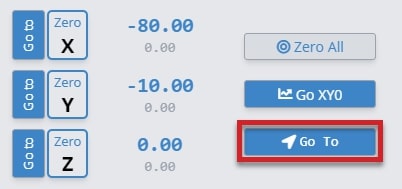
If you want to go somewhere else quickly without manually jogging there, you can also use the ‘Go To’ button to bring you to a specific location. You’ll see a popup asking you where you want to go and you either type a specific location (absolute) or move some amount from where you are now (relative).
You can reset your zeros anytime when the machine is not actively running a job. The machine will remember your zero in most cases. If you turn the lead screw with your fingers or push the gantry, the machine does not know you moved it, therefore it will lose the zero position. You can jog on the Jog Control without losing your zero position because gSender knows you are moving the machine.
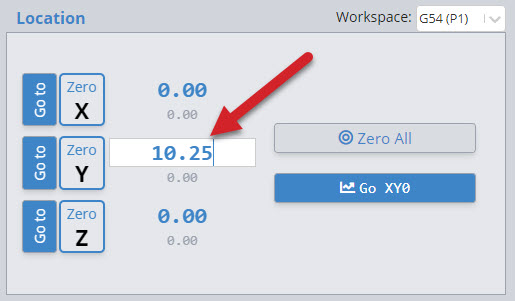
You can also enter coordinates directly by clicking the location value. It’ll turn into a white box where you can type any number, then hit the ‘enter’ key to confirm it. For instance you could set your Z-axis to 0.1mm instead of 0 if you’re using the paper method and you want to account for the paper thickness. Another example is instead of jogging 10mm to the right and clicking ‘zero’ to begin cutting a duplicate job that’s shifted over, you can just type “-10” and start the job right away (since if ‘zero’ is 10mm to the right, then your current location would be 0 – 10 = -10mm).
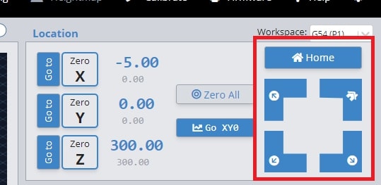
Endstop buttons
gSender provides unique features if you have endstops on your machine for homing or limits. Once homing is enabled ($22) you’ll notice additional buttons appear in the ‘Location’ area of gSender:
- The ‘Home’ button is a convenient way to home or re-home your machine at any time (sends the typical $h command).
- Four “quick-travel” buttons to move your CNC at its maximum speed to any of your machine’s 4 corners (offset by 5mm). These can only be used once your machine is homed, you’ll also notice a house icon appear at the corner that your machine homes to.
- If you’ve set up a “Safe Height” in your gSender settings, now any “go to” or “quick-travel” button will move to the top of the Z-axis minus the safe height before moving anywhere to make sure your machine doesn’t run into clamps or other materials (before it would move up by the safe height amount).
If you’re having issues with the “quick-travel” buttons, then check the “maximum travel” settings for your machine to see if they are the same as what your machine is physically capable of moving. You can find these settings in the Firmware tool as $130-133.
If you’d like more information on how to set up and use limit switches, read here: https://resources.sienci.com/view/lm-adding-limit-switches/
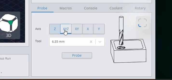
Probing
Probing automatically sets a zero position, usually at the bottom left corner of the stock material, using a touch plate. If you’re not using a Sienci touch plate, read here to make sure your settings are set up correctly.
Usually you’d have to enter a tool diameter each time you probe, but gSender also gives the option to save tool sizes for re-use. You can see this in the ‘Tools’ section of the ‘Probe’ settings. Add different tools by entering the diameter in millimeters or inches, and then pressing ‘Add Tool’, and if you tend to use a specific-sized tool the most then make sure to have it at the top of the list to make it your Default.
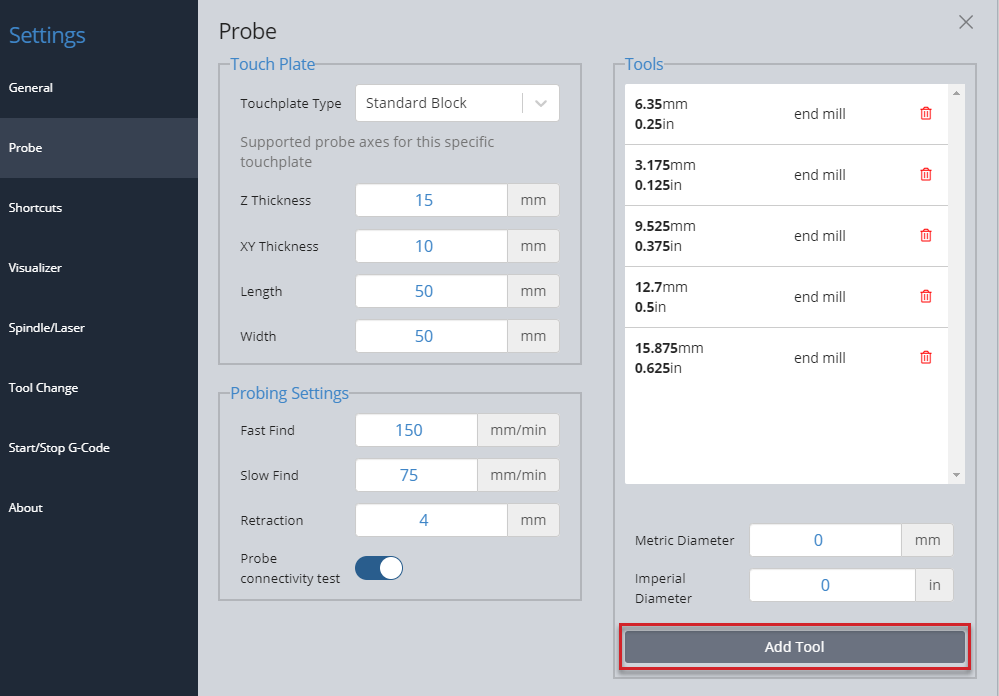
Once you have set up the touch plate, banana plug and magnet on the machine, you can choose which axis to probe for, and the diameter of the bit you are using if applicable. The bit size can be selected from the drop-down of saved bits, or can be typed in manually. Jog the machine so that the bit is hovering over the Sienci Labs logo on the touch plate. Then press ‘Probe’.
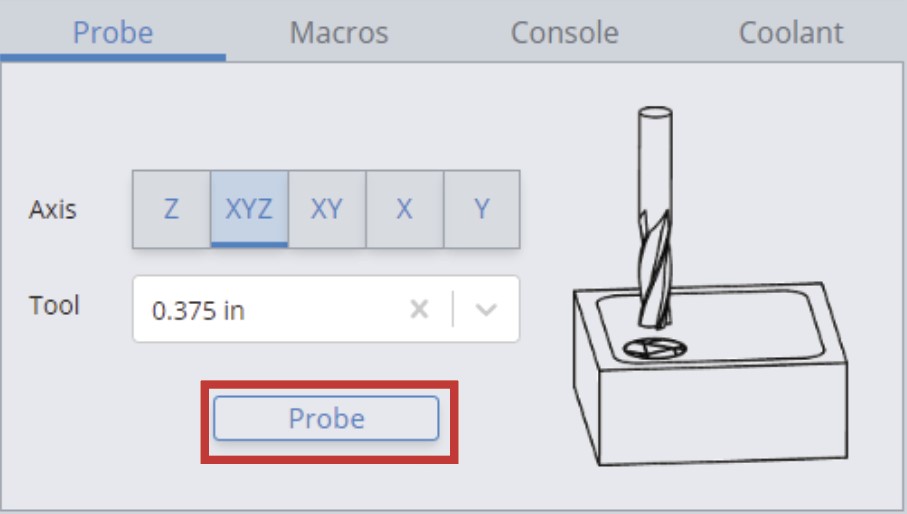
Before the process begins, there is a conductivity test to ensure that the touch plate components can conduct electricity, which allows a signal to be sent to the LongBoard when there is contact. You can either bring the touch plate to the end mill or touch the banana plug and magnet together. Make contact a few times just to confirm there is conductivity, as the red circle should flicker to green.
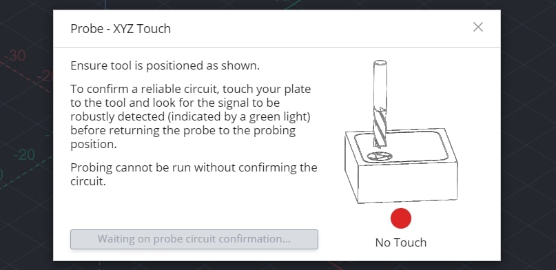
A blue button called ‘Start Probe’ will appear if you have successfully confirmed conductivity. Ensure that the touch plate components are set up for probing, then press ‘Start Probe’. The machine will move to probe three sides of the touch plate, twice on each side. There should not be any crashing or abrupt movement. Once the process is over, remove the touch plate components from the machine and then press ‘Go to XY0’. The bit should be overtop the bottom left corner of the stock material, and pressing ‘Go to’ next to the ‘Zero Z’ should bring it to touch the surface. More information can be found on our touch-plate resource page. https://resources.sienci.com/view/lmk2-touch-plate/
If you have a different setup where probing the front, left corner is less convenient for you, gSender can also probe other corners by clicking the corner button. You’ll see the blue arrow point to the corner you want to probe from, then you can follow the rest of the probing process the same way.
Loading Job Files
If you have already prepared a project file, ensure the following:
- The file is an *.nc, *.g-code, *.tap, *.gc, or *.cnc file.
- The file is exported to the correct post processor for the LongMill. Please see this page for the correct post processor for your CAM software: https://resources.sienci.com/view/lm-post-processors/.
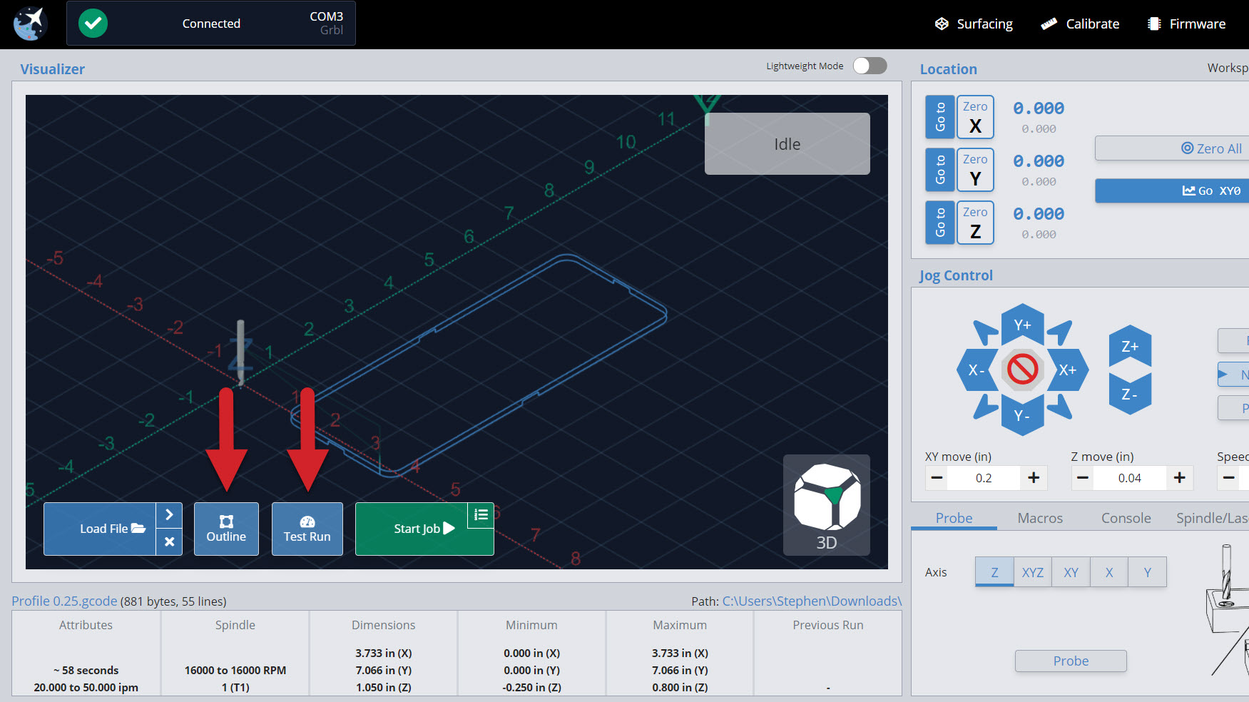
To run your project on gSender, press the ‘Load File’ button. A dialog box should pop up, where you can navigate to where your file is. If you want to reload a previous file you can also click the ‘>’ button which will allow you to select from recently opened files.
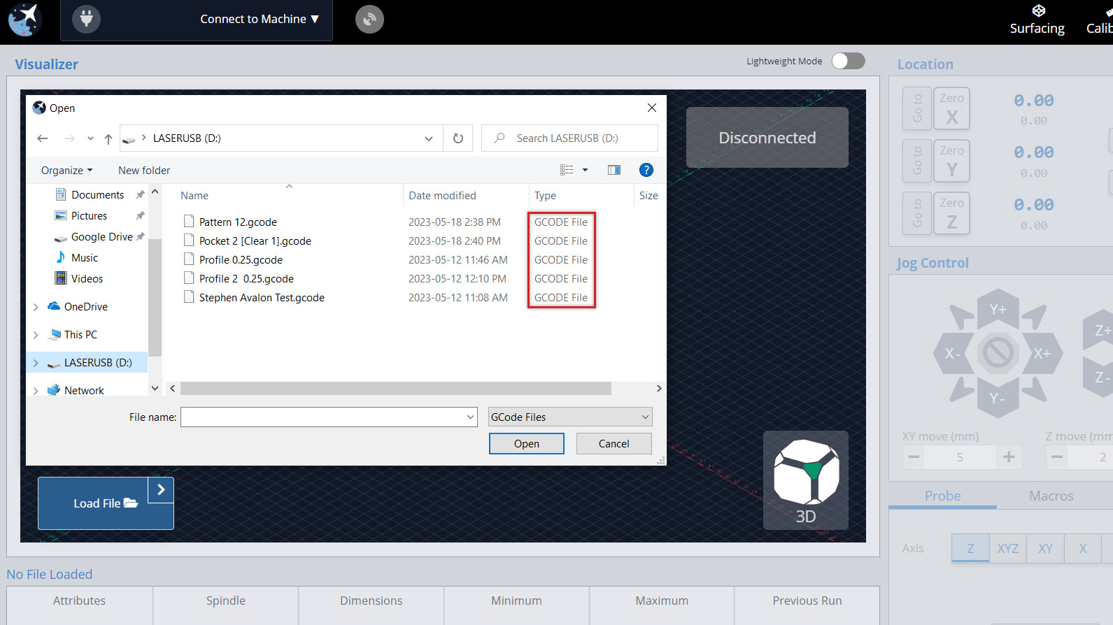
Double click on the file, and the project should load in and be shown on the Visualizer. Once loaded, you’ll be able to see information about your project such as: its estimated cut time and cutting dimensions, and if the file is too big and slowing down your computer you can always click the ‘X’ on the ‘Load File’ button to unload it.
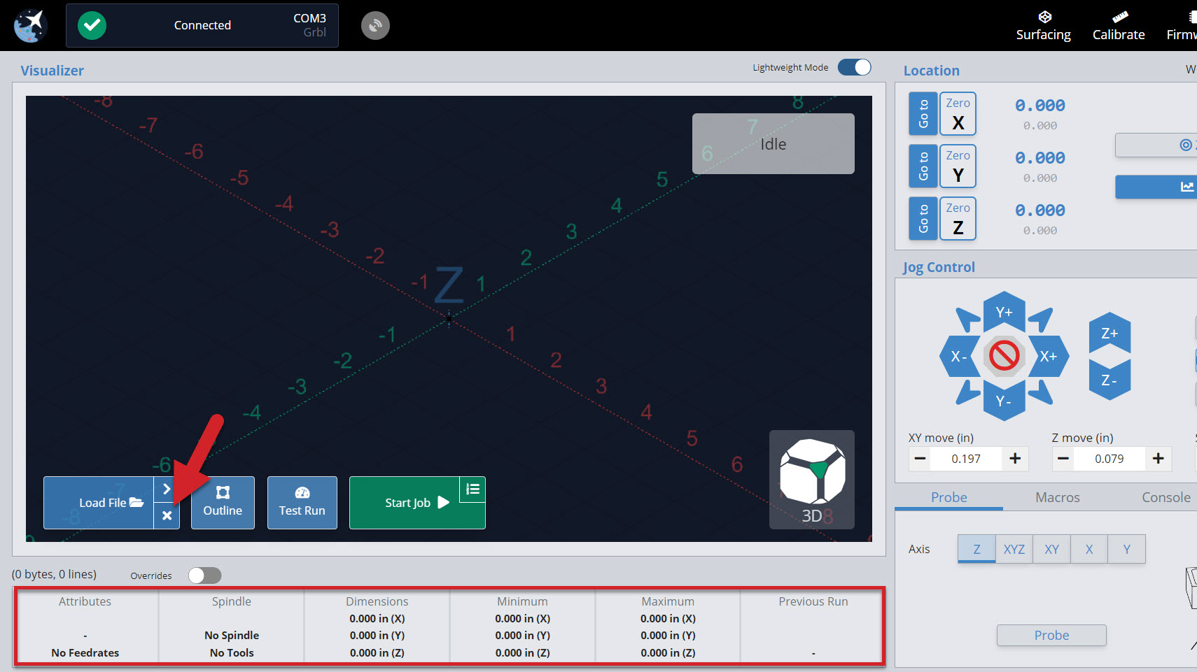
With your file loaded, feel free to also check how it looks. In the bottom right corner of the visualizer use the ‘view cube’ to quickly switch between top, right, left, front, and 3D views by clicking on its different faces. You can also use your mouse scroll wheel to zoom in and out and left-click and drag or right-click and drag on the visualizer to rotate or slide around the work area.
Before running your job there are a few other handy features you can check. The ‘Outline‘ button will physically move your machine around the rough perimeter of your cutting job so you can get an idea of the cutting dimensions and if you’ve positioned the job correctly. As well, the ‘Verify Job‘ (previously ‘Test Run’) button will go through your file and let you know of any obvious errors it noticed before you run the job for real. This button won’t move your CNC at all but if you’re looking to actually “dry run” your file, you can always set your Z-zero high above your material and run the job without cutting anything to see how it looks.
Running Jobs
Once your machine is ready with your router and vacuum on, press ‘Start Job’ to begin your cut. You can pause and stop your job at any time with the respective buttons. If you press ‘Pause Job’, you can resume the job from where you left off. Otherwise, ‘Stop Job’ will cancel your job completely.
Hitting the pause button will pause the movement immediately, even if gSender has plans to move in the buffer (memory). If you are using a macro or Program Events like program pause, this will pause movement more slowly, as the planned moves in the buffer will finish before actually pausing. This is something that can’t be avoided on the firmware side and this is a compromise to be able to execute code at all.
In the default visualizer you’ll see that cutting movements that plan to be made are coloured blue, then when the job is running the current movements show as yellow and past movements are grey.
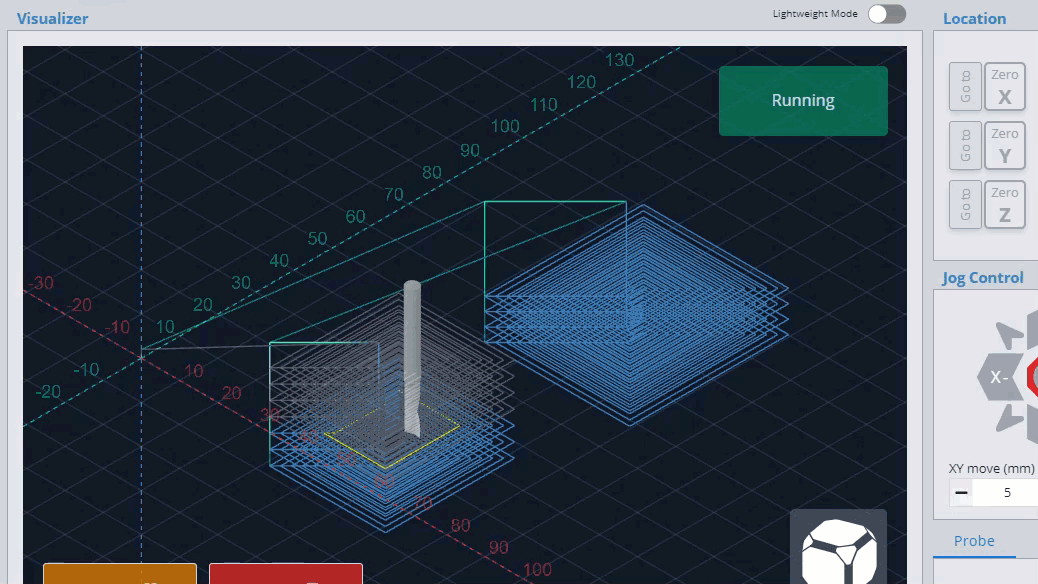
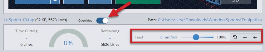
At the bottom of the screen, a progress bar shows how many lines of g-code have been processed and how many are left. Additionally, you can override the feed rate and spindle speed of the program while the job is running by moving then letting go of the slider, pressing the ‘+’ and ‘-‘ buttons for smaller adjustment, or clicking the rotated arrow to reset back to the default value. This is handy for fine-tuning the program cutting speed in order to tune in your material removal rate and ensure you don’t burn or melt material.
If you already know you’ll need to tweak the feed rate or spindle speed for your file before you run it, you can now click the ‘Overrides’ toggle to access overrides before you start the job. This allows the overrides to apply before starting cutting or if the job is already running toggle it back to double-check the job attributes.
Now you’re off and cutting, what a thrill! While your job is running keep an eye and ear out for anything you don’t expect. You can always use the job control buttons during operation to change speeds, pause, resume, or stop cutting altogether.
Job Loss Recovery
Also called “Start from Line”, this feature can recover a carve you were working on that:
- You had to manually stop part-way through
- Was disrupted by a power loss, USB disconnect, mechanical malfunction, or other failure so you need to resume from where it failed
- Was really long, so you want to resume carving after pausing it for the night
- You only wanted to run part of the job anyway
It does this by looking through the whole g-code file up to where you want to resume running to see all the movements up to that point, what accessories were turned on, the power of a spindle or laser, and runs any automatic commands you’ve set up in gSender. This way you can be confident in returning to your projects, even when something has gone awry.
Steps to Resume Cutting
- Make sure to have the g-code file loaded that got interrupted (or that you want to start carving part-way through).
- If you think your machine lost its location:
- Re-home the machine (it should remember the zero location of the project if nothing else moved).
- If you don’t have limit switches, the project moved, or your original cutting bit broke, try to re-use whatever setup method you used to set your zero location originally. This could be with a touch plate, 3D probe, paper method – whatever possible to set the project back up the way it was before it failed.
- Once everything looks set up correctly, you should be able to ‘Go to’ the original zero position and see that the bit is lined up correctly to the material. The location should read all zeros for each axis.
- Raise up the Z-axis a couple millimeters for safety.
- Click the small icon at the top right of the green ‘Start Job’ button to open the window.

- Here you’ll see:
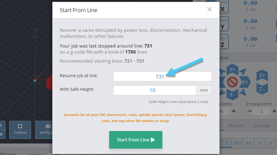
- When you Last stopped your file, how many Total lines it has, and a Recommended start line: this number is generally reliable to use, but in some situations the ‘last stopped’ number can’t be recovered. In these cases you’ll want to have noted down the approximate line number that the job failed at then work from there.
- Resume job at line: once you’ve decided where to resume from, you can type the line number in here.
- Safe height: if your CNC has extra Z movement above the failed job, you can put a larger number here to make sure that it doesn’t hit clamps while moving into position to resume cutting.
- When you Last stopped your file, how many Total lines it has, and a Recommended start line: this number is generally reliable to use, but in some situations the ‘last stopped’ number can’t be recovered. In these cases you’ll want to have noted down the approximate line number that the job failed at then work from there.
- Once everything looks good, remember to turn on anything that isn’t automated like a trim router or vacuum, then click ‘Start from Line’ to resume cutting.
Example: you were present when the job failed and hit ‘Stop’ immediately. Nothing moved but the bit broke so you swapped it out and used a touch plate to probe Z. It says the last recorded line was 731 but to be safe you’ll subtract 20 and start at 711. The job starts back up a little before the failure and you’re able to resume as expected. If instead you hadn’t been paying attention for several minutes then you might subtract 50-100 lines instead just to be safe.

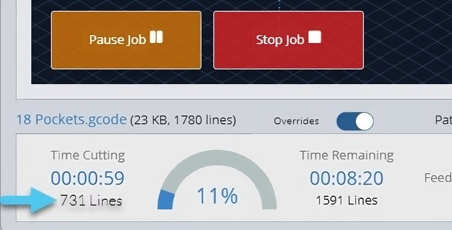
Pause Cutting Mid-Job
- If a carve is dragging on and you need to leave the machine for the night, first you’ll want to note down the approximate g-code line number it’s at. In the example below you’d note down “731 lines”.
- Once noted down, ‘Pause’, then ‘Stop’ the job. This allows the machine to stop more slowly instead of emergency stop.
- Quickly turn off anything that isn’t automated like a router or dust collector and jog the Z-axis up so you don’t burn or mar the material. You can also try to pause strategically when the bit is moving and not cutting to avoid damaging your material.
- At this point it’s best to return the cutting tool to the project zero point if possible using ‘Go XY0’ then ‘Go to’ for the Z-axis. This way if the zero point is lost when you resume cutting later, then you can just manually set your zero knowing you’re still at the zero location.
- If you’re concerned your machine might drift over time for example if you’re using a heavy spindle, then another option is to place a block of wood under your cutting tool and jog down to it using the paper method. Once the bit is touching, you can note down the location where you left the machine, then when you resume you can type that location back in (see the end of [Set Zero and Go tos](#set-zero-and-Go tos)).
Safety
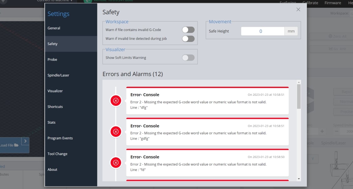
gSender is set up to do many things by default to help keep you aware about things going on with your machine. Though we can’t guarantee it can handle everything, we’ve recently introduced a new Settings menu for Safety where you can access many safety items in one place. This includes:
- Warn on Zero: an optional popup that appears when you click to ‘zero’ just in case you mis-clicked it.
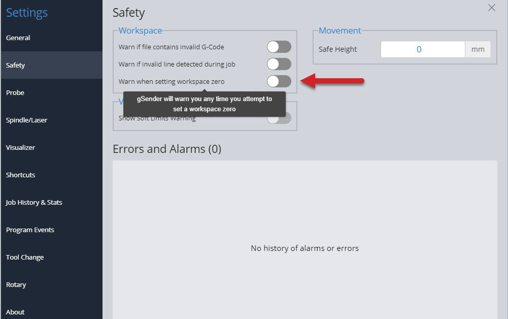
- Safe height movement: this number is used when using the ‘Go to’ buttons in gSender to manually move your machine around (it’s independent from a safe height you might set in your CAM software). For machines without homing, entering ‘5mm’ will make it move 5mm upwards from the current position, make the Go to movement, then move 5mm back down. If your machine has homing, it’ll move to 5mm from the max Z-axis travel, make the Go to movement, and then return back to where the bit started. This behaviour helps homing-capable machines to reach a more ideal safe height to avoid collisions during movements.
- G-code warnings: reports back when it sees g-code lines that don’t look correct when the file is loaded or once it’s being sent to the machine. G-code has to follow specific ‘grammatical rules’ similar to other languages for the ‘sentences’ to be correct, so if the lines don’t look correct then your machine might run into problems understanding what it’s supposed to do.
- Soft limits warning: enables gSender to tell you when a loaded file might exceed the cutting area of your machine. This requires that your machine has limit switches and soft limits enabled.
- History of Errors and Alarms: great for tracking problems you might’ve recently run into to help troubleshooting or getting support. All entries are listed in-order and stamped with a date and time.
Shortcuts
Starting off as a more advanced gSender user, the first feature you’ll want to leverage is shortcuts. These can allow you to assign gSender or CNC actions to keys and key combinations or even to gamepads and joystick movements. There are 3rd party apps like JoyToKey, Xpadder, Comfort Keys Pro and reWASD that allow you to do this, but to eliminate needing to download and configure other programs we’ve rolled all the functionality into gSender itself.
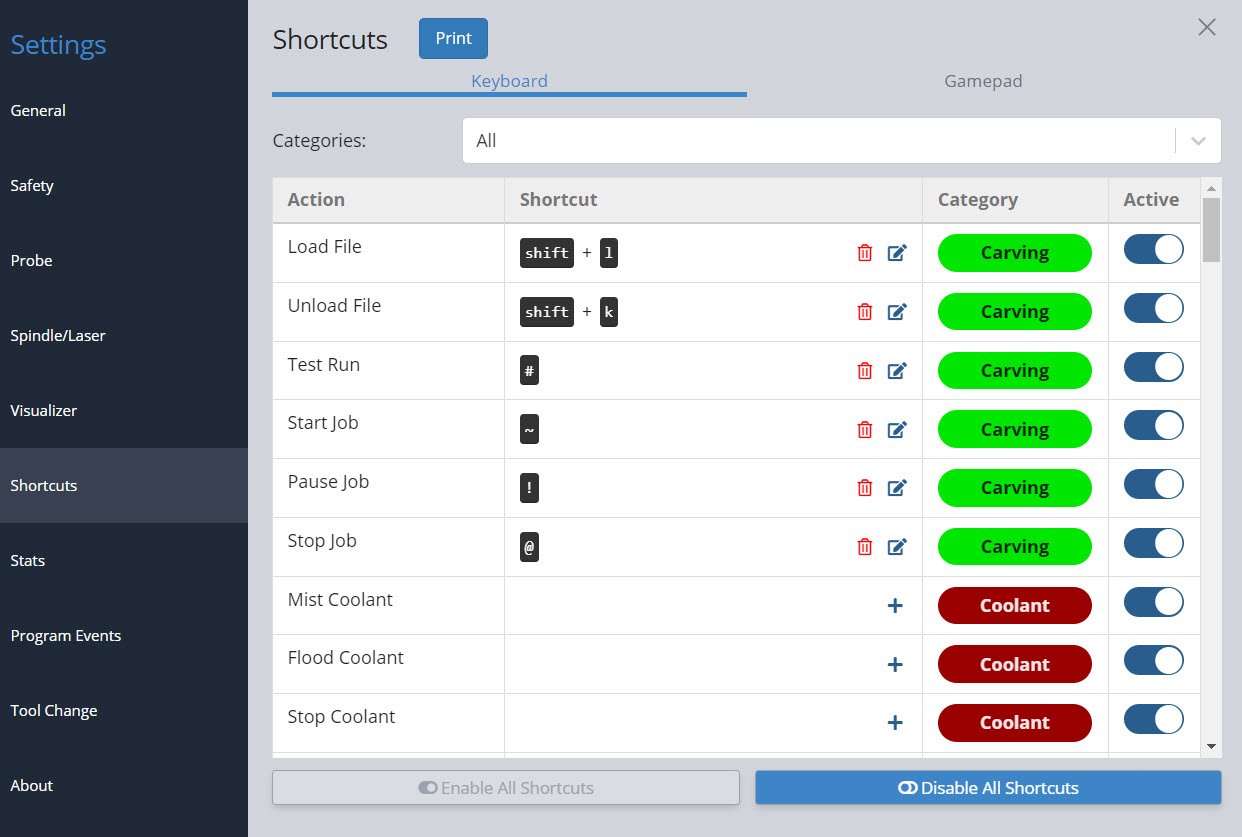
Going to the settings gear, then the ‘Shortcuts’ section, you’ll see that shortcuts can come in the form of ‘Keyboard Shortcuts’ or ‘Gamepad Shortcuts’, all searchable by category. Both options enable you to set up, modify, and enable or disable shortcuts. These will be automatically saved when you close the dialog box and will remain on gSender as long as the program is installed on your computer.
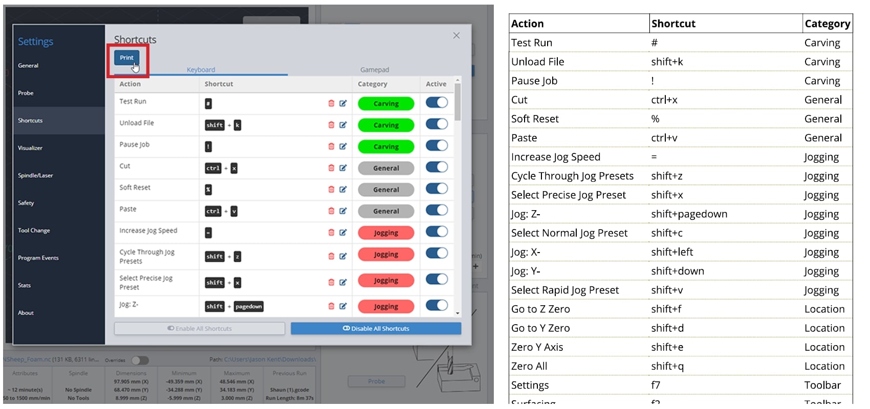
Shortcut Printing
Find yourself forgetting how you’ve configured your keyboard or gamepad profile shortcuts? Hit the ‘Print’ button to generate a simple PDF that you can store on a tablet or print on some paper to keep next to your CNC. This PDF will contain all the shortcuts you’ve created and what actions they’re assigned to.
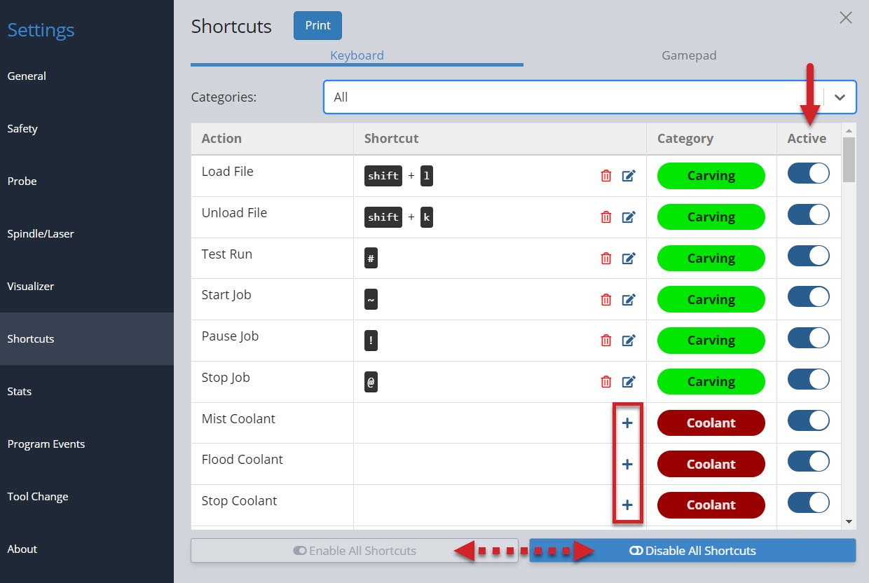
Keyboard Shortcuts
Either for use on a keyboard, macro pad, or mini Bluetooth keyboard, these are split up into categories so they’re easy to locate and modify. There are shortcuts for carving, overrides, jogging, zero setting, probing, macros, visualization, window navigation, and more!
Common Shortcuts
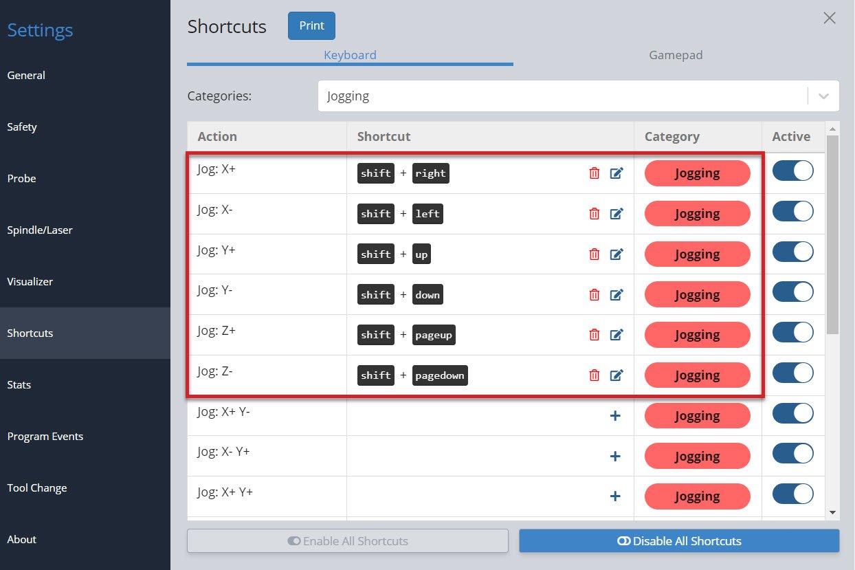
A great place to start is the Jogging category. In the picture below, see that right now we can jog the X-axis by hitting the shift + right or shift + left keys. The Y-axis responds to shift + up and shift + down keys and the Z-axis uses the shift + pageup and shift + pagedown keys. Being able to look at your CNC, while your hand is on your keyboard is a great way to ensure you are moving in the right direction, without having to look back at your screen to click the mouse on the right button.
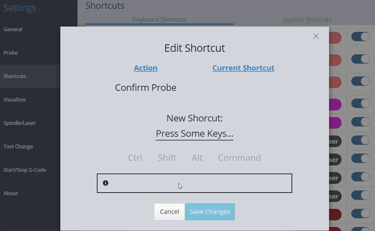
You can use the preset shortcuts and/or add your own. Click the ‘+’ or the ‘edit’ to the right of each shortcut to bring up a popup window that allows you to add or edit your own key combination (shown in the example below). You can see it’s as easy as pressing the key or key combination once the popup is open. In addition, you’ll be informed if the combination you’ve entered is already used elsewhere and be given the option to overwrite the existing one if you want.
You can turn on or off individual shortcuts in the Active column or enable/disable all shortcuts at the bottom of the window. Some people find this useful since it can turn off the shortcut temporarily without losing the key combination.
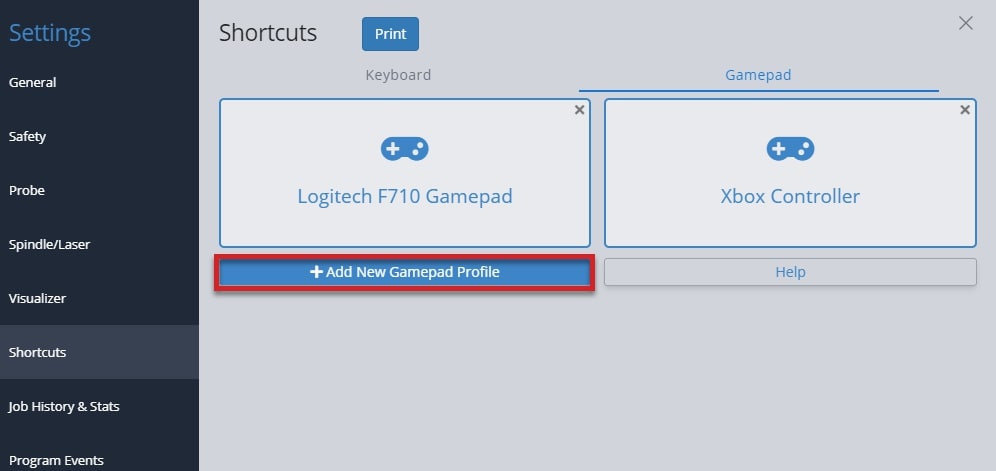
Gamepad Shortcuts
Many users really love this feature since using a controller is convenient (especially for when you’re closer to your machine), inexpensive, and makes certain repetitive actions much easier. Common options are Xbox, PlayStation, and other third-party controllers available to buy online.
We have some pre-made profiles for gamepads we’ve already tested with gSender and you can still reference these if you have a different gamepad or want to make your own. To create your own, connect your gamepad to your computer and click the ‘Add New Gamepad Profile’ button, then make sure the gamepad is recognized before beginning to assign actions to each button. These profiles mean you can set up multiple gamepads if you’d like since they each have their own unique ID.
If you run into difficulty with getting a particular gamepad set up in gSender, consider:
- Some gamepads may require drivers to be downloaded so your computer can read the signals that the gamepad sends out.
- Go into the gamepad profile while it’s connected and click the Help button where you’ll be able to diagnose whether your gamepad is broken and sending out bad signals.
- Searching for documentation provided by the manufacturer (for example, Xbox or PlayStation).
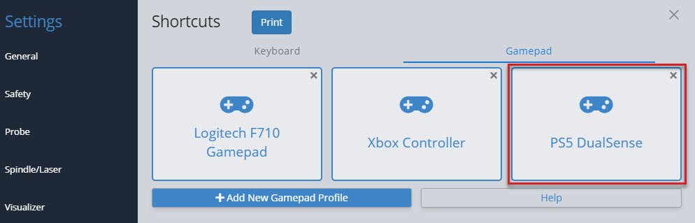
Tested Gamepads
To better guarantee your experience using a gamepad in gSender, we’ve taken the time to test a shortlist of some common and affordable options that are easy to source. With community help, we hope to continue growing this list of officially tested gamepads which currently includes:
 |
YCCTeam Xbox Controller
|
 |
Logitech F710
|
Having a listed gamepad means you can both be more confident that your hardware will be compatible with gSender, as well as many of the ‘tested gamepads’ will have pre-made shortcut profiles built right in to save you time setting up your own. Find these pre-made ‘profiles’ alongside all the other gamepad settings in the Shortcuts ➜ Gamepad tab.
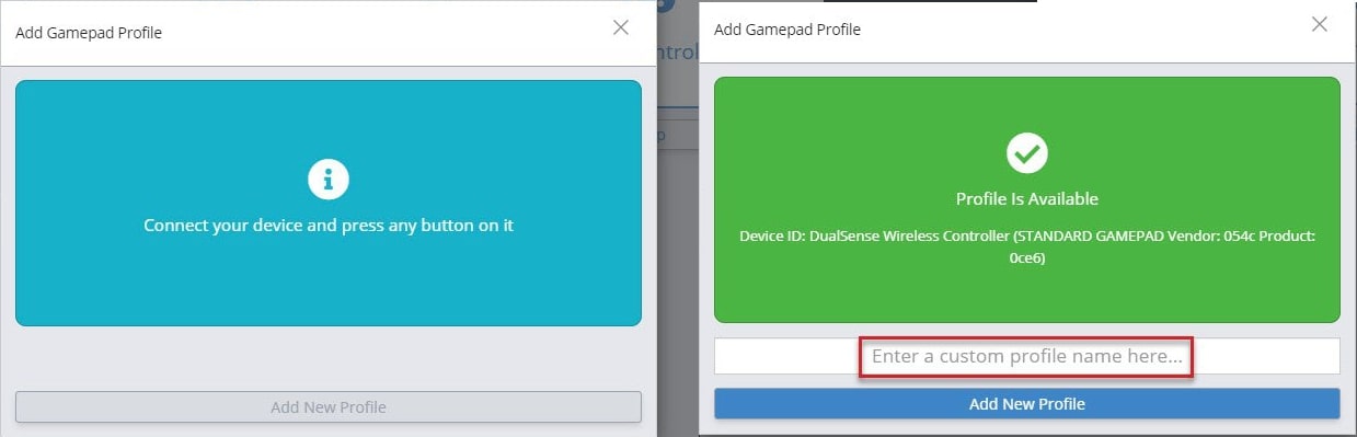
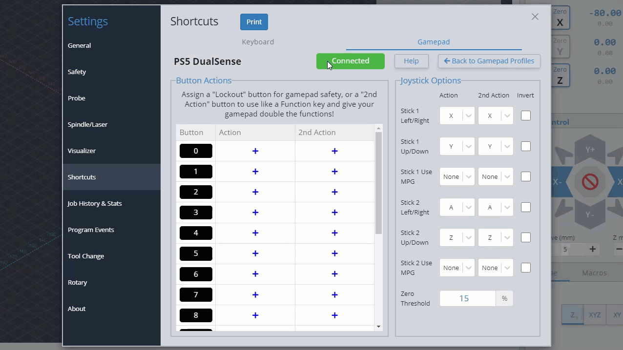
Connect your controller to your PC and press any button on it. gSender will identify and provide a profile if one is available. You can see in the screenshot below, it correctly identifies the DualSense Wireless Controller I’m adding. Enter your profile name and hit Add New Profile.
Gamepad Setup
Once you have a profile for your connected gamepad, click on that profile to edit it.
Inside a profile, you’ll be able to see if that specific gamepad is currently connected and be able to assign shortcuts to the two major groups: buttons, and thumbsticks.
Buttons are the most versatile in how they can be set up. Any button on your gamepad can be set up to:
- Activate an action
- You can assign a button as a ‘Second Action Button’ which acts similar to a ‘Shift’ key on your keyboard to allow you to create two-button combinations on your gamepad.
- You can also assign a ‘Lockout Button’ which acts as a safety lock for your CNC when controlling it with the gamepad. If you set up a lockout button, then no other buttons on the gamepad will work until you’re pressing on the lockout button. This stops from pressing buttons accidentally or if you dropped your gamepad on the ground.
To add an action to a button, start by pressing the button on your gamepad to see which one on the list lights up green. In this case, the X button lit up button 0. After pressing the + symbol in the Action column, you will see a list of actions you can map to that button. In this case an action was added for Homing – Go to back left corner, so now when the X button is hit on the gamepad, gSender will move the CNC to the back left corner!
You can repeat these steps to keep adding more shortcuts to your gamepad, this also includes:
- If you’re having difficulty remembering your gamepad buttons, you can click on the black box label and rename it to whatever you’d like.
- The ‘2nd Action’ column will allow you to give each gamepad button a second shortcut action once you set up a ‘Second Action Button’. Do this by clicking the
+symbol in the Action column of the button you want to use, then clicking the ‘Use as Second Action Button’ toggle on the right side. - Assign a ‘Lockout Button’ in a similar way but by toggling the ‘Use as Lockout Button’ toggle on the right side.
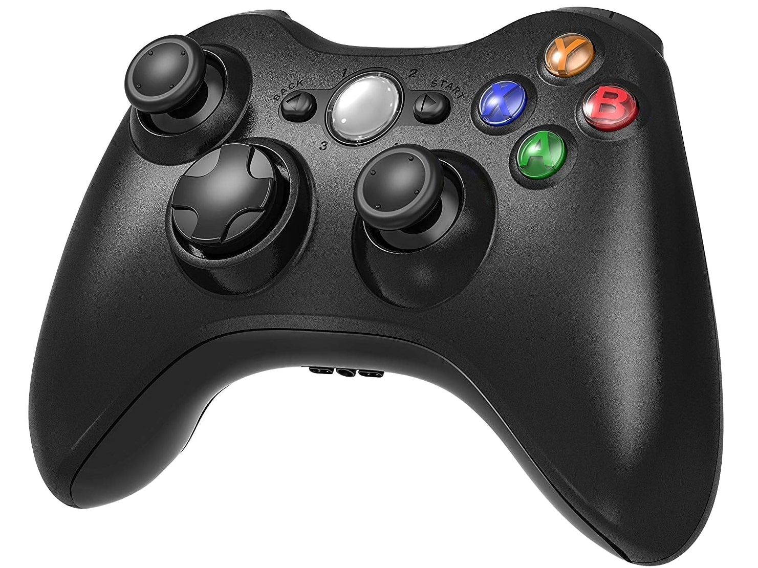
Thumbsticks are set up to be used for jogging because of the ability to move them a little or a lot, which is different from buttons which can only be clicked on or off. This works well because most gamepads tend to have 2 thumbsticks (like the Xbox controller shown above), meaning you can use one to jog in the X and Y, and the other to jog in the Z and A (if your machine has a rotary axis). For gamepads that don’t have thumbsticks this is still fine because buttons can also be set up to jog.
On the right side of the gamepad profile window, you can see the options for what axis you’d like to move with your gamepad thumbsticks. Similar to setting up buttons, you can move the thumbstick to see which one lights up, and you can also assign a ‘2nd action’ if you’d like. In this example, Stick 1 controls the X-axis left and right, and the Y-axis forward and back while Stick 2 controls the A-axis with left/right and the Z-axis with up/down.
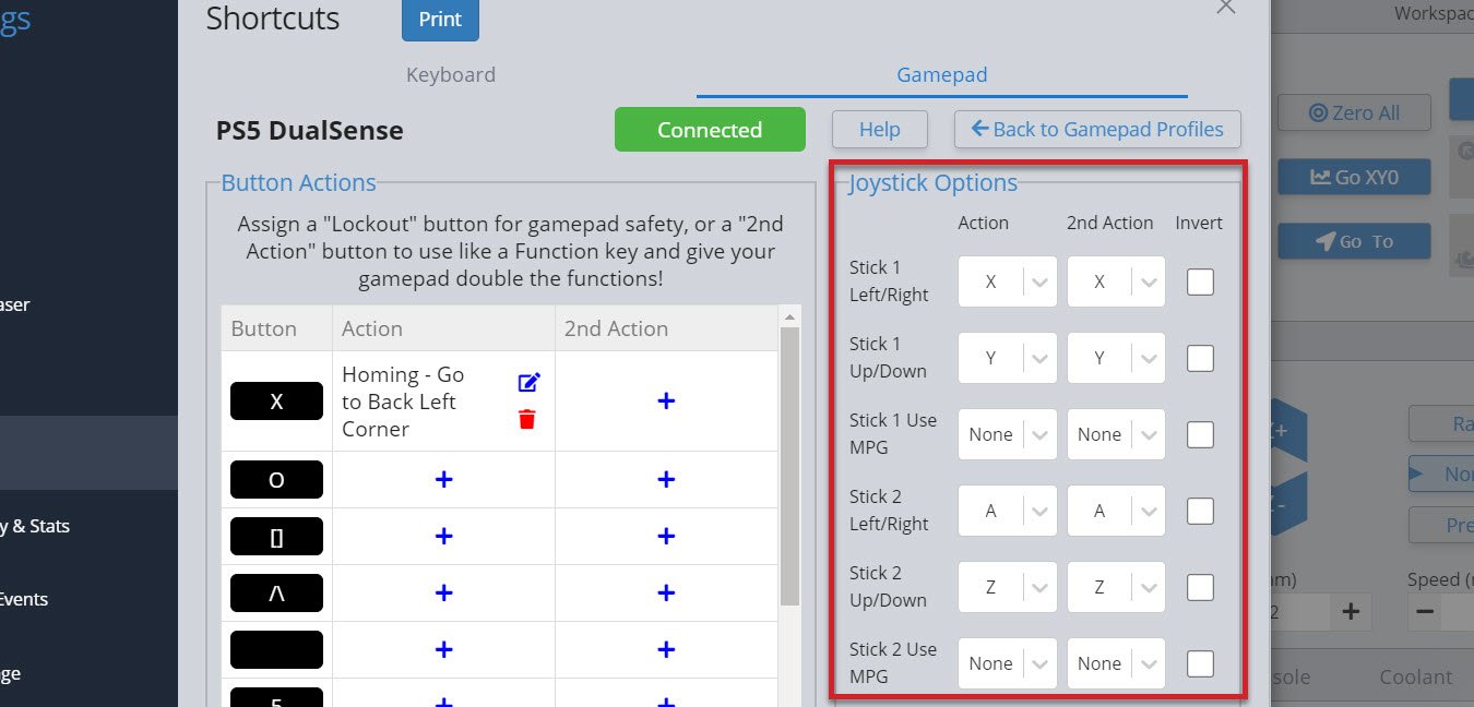
Once you’ve set up your thumbsticks, you’ll find you can push them any amount and the distance you push them will decide the speed that axis moves at. If you’ve set up both the left/right and up/down, you can also mix these to make continuous diagonal movements to get to your final location easier. You can also flick the thumbstick once and the CNC will move one increment, according to the rapid/normal/precise movements you have set up for Jog Controls.
- If you find your thumbstick is moving the axis in the wrong direction, use the ‘Invert‘ checkbox to correct that
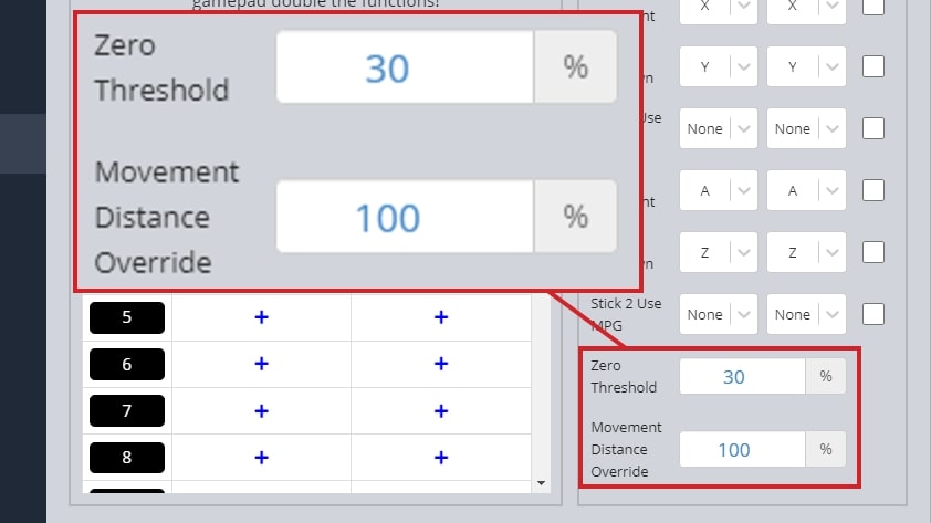
- If you let go of the thumbstick and the axis keeps moving, increase the ‘Zero Threshold‘ amount since your gamepad might be older and more worn out
- If you get jittering while moving with the thumbsticks, or you let go of the sticks and it takes a while to stop moving, you might want to adjust the ‘Movement Distance Override‘ value until you get smooth movement on your setup
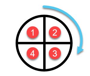
Another cool feature is the Use MPG selection. If you map one of your thumbsticks to an axis with MPG selected, it will automatically grey out the other stick selections. Now you can rotate your stick in any direction and for each quarter rotation, your axis will move once, according to your preselected Jog Controls.
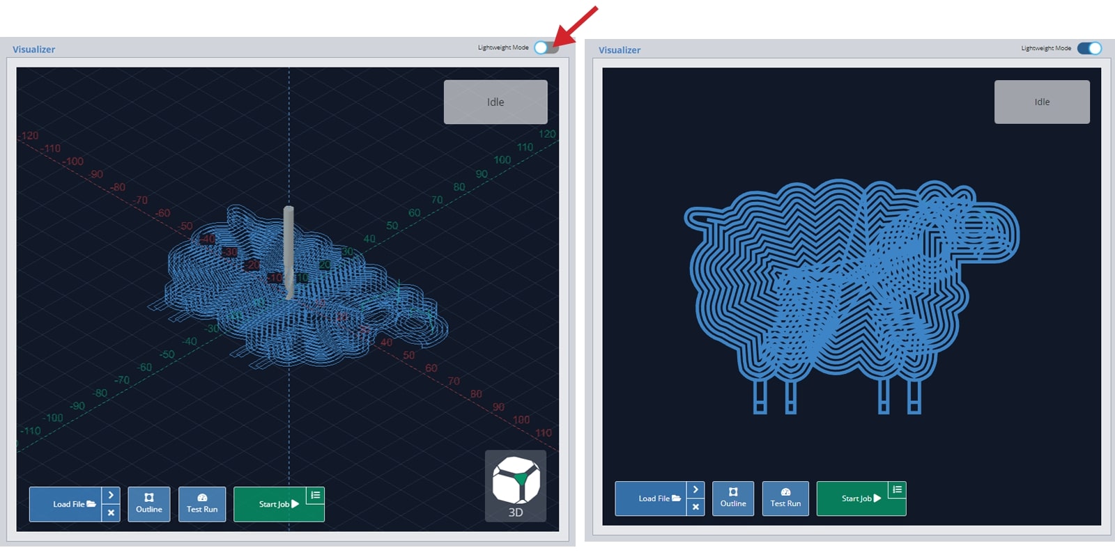
Lightweight Mode
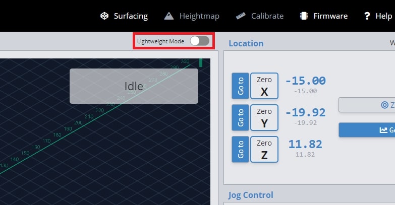
This mode enables gSender to run faster on computers that are less powerful and prone to lagging. ‘Lightweight Mode’ reduces the memory gSender uses by turning off processor-heavy aspects of the visualizer, from reducing detail to disabling it altogether. You can toggle it on or off using the slider positioned at the top right of the visualizer.
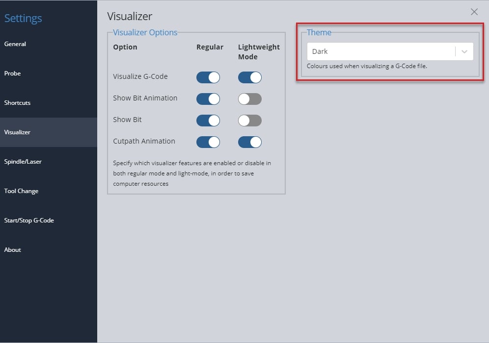
If you go to the visualizer settings, you can also customize what features are active in both ‘Regular’ and ‘Lightweight’ modes.
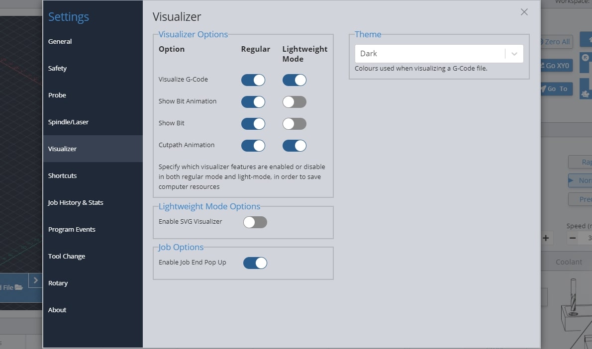
If gSender’s visualizer is impacting the performance of your machine but Lightweight mode only helps once the whole visualizer is turned off, this hybrid option could help. Found in the Visualizer settings, the ‘SVG Visualizer’ substitutes the default 3D viewer with a pre-rendered, top-down image of your project, drastically reducing computer strain but still allowing the project to be displayed.
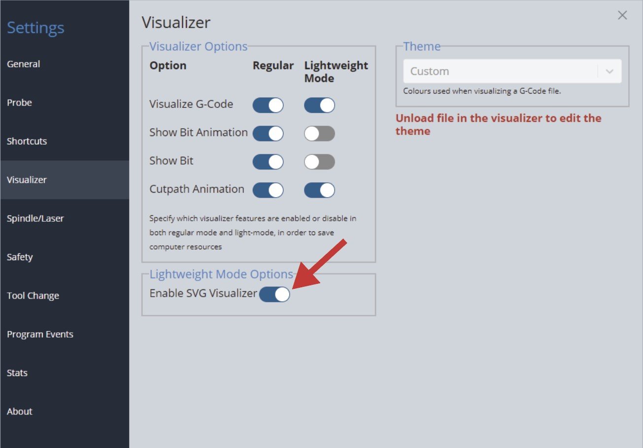
Once you toggle on ‘Enable SVG Visualizer’, whenever you turn on Lightweight Mode in the top right of the visualizer, you’ll see the alternate view with all animations turned off.
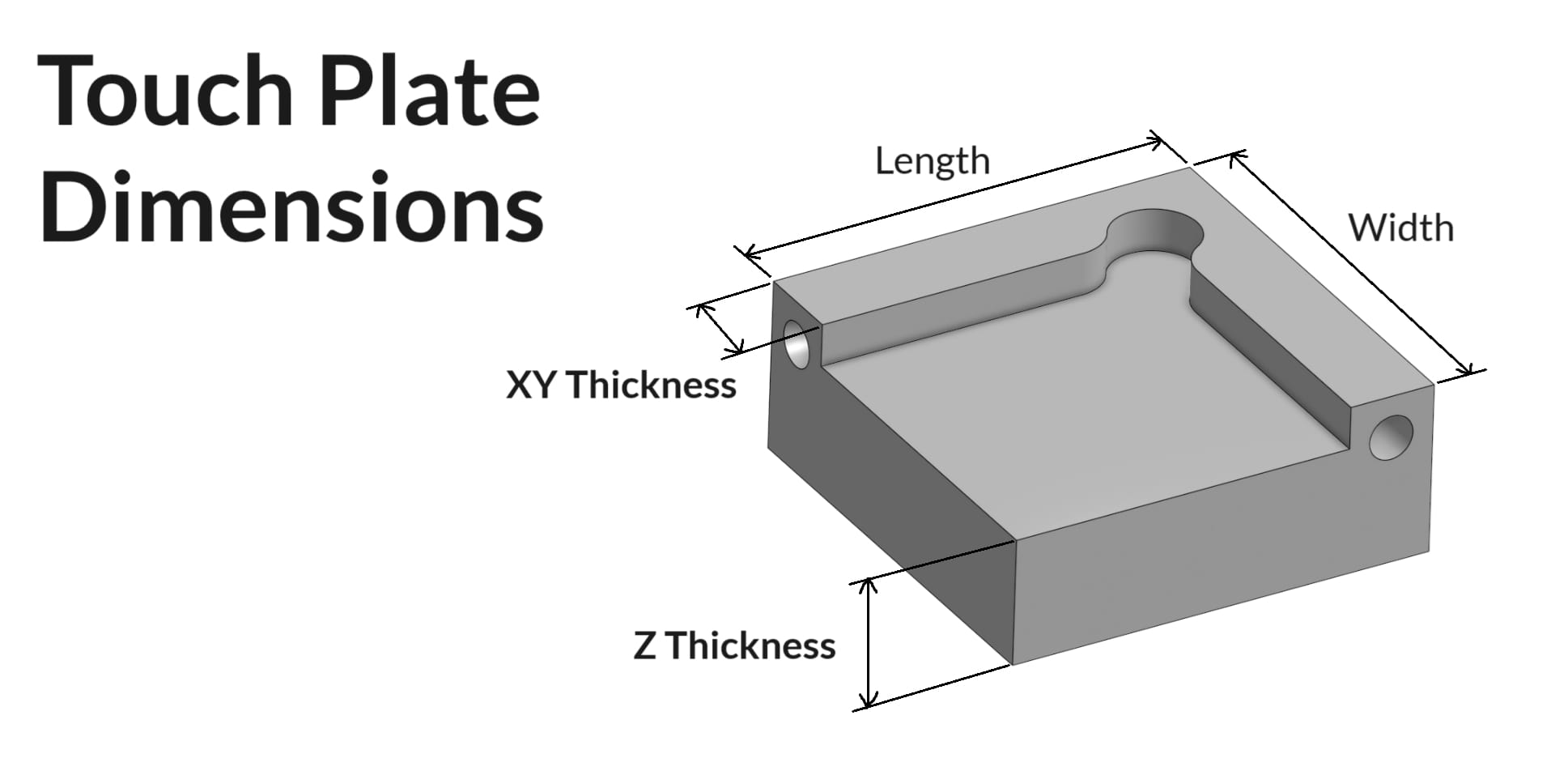
Touch Plate Setup
gSender has support for three types of touch plates:
- The Standard Block design
- Z Probe, also sometimes referred to as a ‘puck’
- And our specialized AutoZero touch plate
For a Z Probe, setting up is simple since you just need the thickness of the ‘puck’. Enter that value into gSender’s ‘Probe’ settings under ‘Z Thickness’ and you should be good to go!
If you’re trying to set up a custom ‘standard block’ plate, use some calipers to pick up on the measurements noted below. Once these are noted down, enter these into gSender’s ‘Probe’ settings in similarly named entries, and now you should find that gSender’s probing routine has been altered to fit the shape of your touch plate.
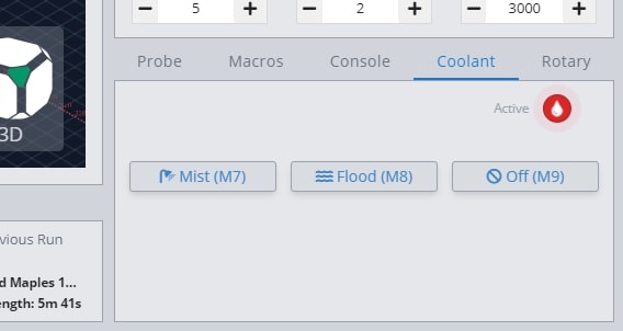
Coolant Control / IOT Relay
If you have a coolant control pin on your CNC machine, gSender has a tab for manually controlling it. Under the ‘Coolant’ tab on the main screen, you can find the ‘Mist’ and ‘Flood’ buttons to activate the different modes of coolant use, as well as an indicator for whether the coolant function is active or inactive. This indicator also functions during job sending. You can turn off both coolant pins by pressing the ‘Off’ button.
Many hobby CNCers don’t have a need for coolant and so prefer to use these outputs for controlling other periphery. The most common is an IOT relay that can be used to automatically control a vacuum for dust collection, the CNC’s router, LED lighting, and more. See an example of how to set that up here: https://resources.sienci.com/view/lm-iot-relay/
Spindle & Laser Support
Similar to the manual coolant control, this area is for manual control of a spindle or laser outside of g-code sending. If you have a spindle or laser, you can activate these controls by going to the settings gear at the far right. In the ‘Spindle/Laser’ section in the left toolbar, press the toggle for ‘Spindle/Laser’.
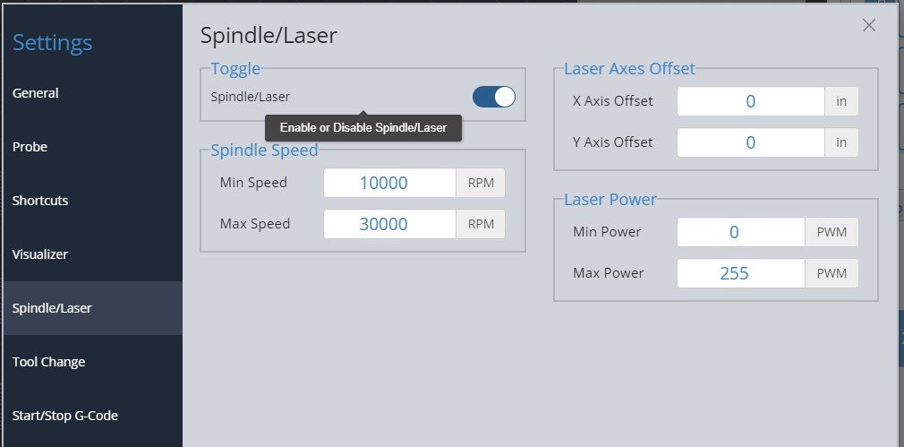
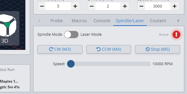
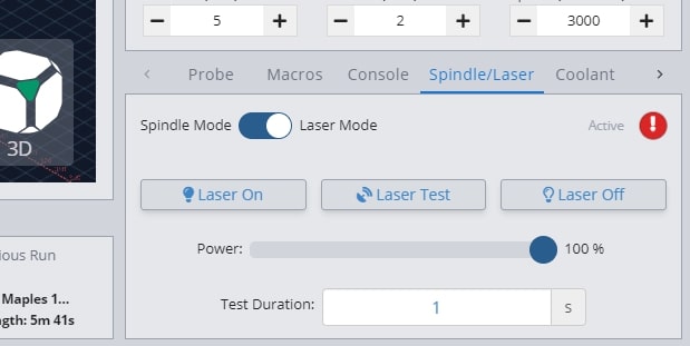
Back at the main screen, you’ll see the ‘Spindle/Laser’ tab at the bottom right. Here you can click to toggle between ‘Spindle Mode’ and ‘Laser Mode’, changing your grbl settings for you and displaying buttons specific to each device. For each mode there is also a red caution circle that indicates whether the spindle or laser is active. This works during manual control but also during job sending.
In spindle mode you can set the spindle speed with a slider, spin it up in either direction, and stop it again with the ‘Stop’ button. These are all based on g-code commands that can also be entered into the console manually if desired. The speed slider is set from your grbl firmware settings, so max and min speed can be altered in the Firmware Tool.
‘Laser Mode’ is very similar, allowing for On/Off control, a slider for setting the laser power during manual control, and a ‘Laser Test’ button. The laser testing function is handy when troubleshooting your laser setup or for other sorts of locating and alignment because it only enables the laser for a short time before turning it back off again. Though this is much safer than regular on/off control, we still highly advise that you have you have a hand on a kill switch or E-stop during testing or control of either Laser or Spindle modes so that in case something goes wrong with your computer or the program they can still be safely deactivated.
Laser Diode Support
Some accessories can be really handy to add to a CNC router like a laser diode, drag knife, or pen plotter. These would all perform better on a faster, dedicated machine, but for occasional use why not use the existing motion system of the router to do other things for you? A laser diode in particular can be great because you can clamp the material to carve and then laser engrave afterwards and know that everything is still aligned.
Since many CNCs are coming with diode accessories, gSender has some unique features to also support lasers. Once ‘Laser Mode’ is turned on, gSender will:
- Automatically apply an offset from the router/spindle to the laser so all your g-code files stay aligned (configured in the Spindle/Laser settings, or with Firmware settings $741 and 742 on the SLB)
- Turn on the laser at low power when running a job outline (enabled in the Spindle/Laser settings). This will help you to better see where your project is going to be located on the material
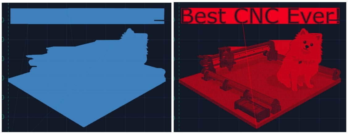
- Switch to a specialized visualization designed to show raster engraving images better than typical g-code visualizers. Seeing the laser intensity in the movements is very useful to get a better idea of what your projects are going to look like when they’re run. This will only apply to files loaded after ‘Laser mode’ is enabled and the colour can be customized in the settings
Macros
Macros are standalone buttons within the gSender interface that allow you to execute a series of g-code commands when they’re run. Macros can come in handy for a variety of uses:
- Button to run a v-carve or laser engraving of a common insignia into the back of your wood pieces
- Perform a specialized probing function for a particular jig you’ve set up
- Apply a predetermined offset that allows you to easily array your cutting jobs
You can create macros using the ‘+’ button under the ‘Macros’ tab. Here you’ll see a space for inputting your custom g-code and adding a name and description for the macro. Advanced users may also want to leverage ‘Macro Variables’ which allow for greater g-code manipulation and pseudo-programming. Press ‘Add New Macro’ when completed.
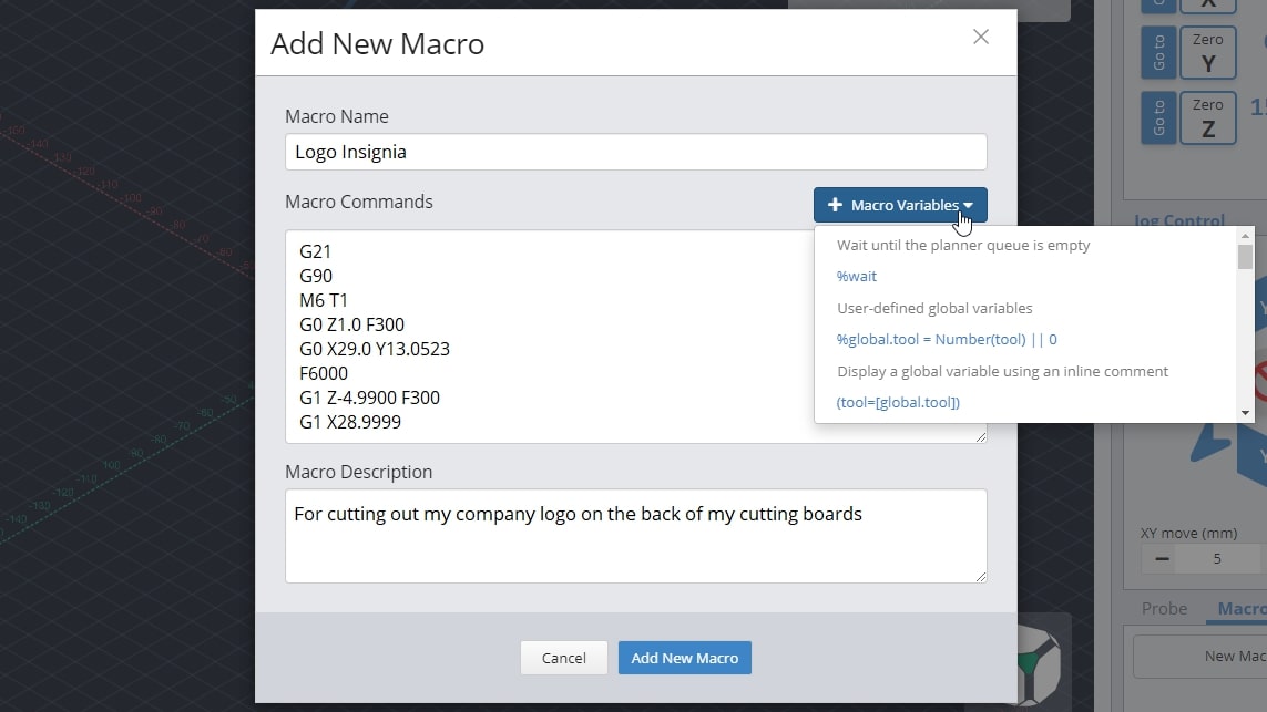
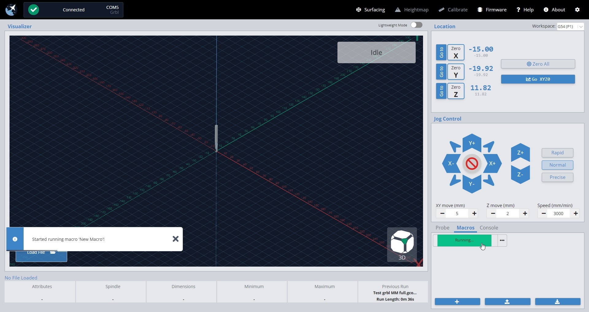
New macros will appear as buttons in the ‘Macro’ tab that can be rearranged by dragging them around. These buttons will display the macro name, show the description if you hover your mouse over them, and can always be later altered or deleted by clicking on their ‘…’ button.
Any macro can be executed by pressing it. Before pressing it, a play icon will appear to show that you can select it. Once running, you should see the macro start to pulse green while a toast notification on the bottom left hand side of gSender also notifies you that it’s running.
Macros can also be executed using shortcuts. Every time you create a new macro it’ll become available at the bottom of the shortcuts list for you to assign a key or gamepad button to. Add your keybindings and enable them by pressing the slider beside the label.
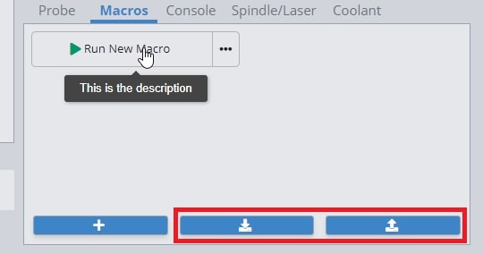
You can share macros with other users or transfer them between computers by using the import and export features. To import one or multiple macros, just press the button with the downward arrow and a browsing window will appear so that you can select the macros you wish to import. Similarly, to export all your current macros, press the button with the upward arrow and it’ll generate a save file for you.
Advanced Macros
gSenders Macro architecture is based on JavaScript and uses the Esprima library (https://esprima.org/) and so will theoretically support any code that it does. This is exciting because Macros can move far past basic variables if you’d like to perform advanced functions on your CNC:
If you want some initial inspiration, see other macros made by our community or ones made for CNCjs (another g-code sender) which should also work in gSender. Otherwise, here are some other points of guidance:
- You’ll want to develop your understanding of typical g-codes and m-codes that are used for CNC control (the pages linked are very good sources for that)
- The “Macro Variables” dropdown in gSender shows many of the most commonly used operations when making your own macro
- Make your own variable with
%variable = value_you_want_to_set(ex. % probeSpeed = 150) - Use your variable in g-code, like
G21 G91 G0 X[variable](moves the X-axis by the amount set in the variable) - Test your code by printing it to the console
([variable]) - Make dialog boxes appear on the screen to confirm a value or position by putting in an M0 line with a comment, for example
M0 ;Remember to turn on your router before the next stepwhich will pause the macro and give you the option to ‘continue’ or ‘cancel’ - Start experimenting with basic math using numbers and variables
- Use global variables
global.variableif you want variables that you can use in other macros (note that these get reset once gSender is closed) - Read up on all the other Math features available like absolute value, rounding, and trigonometry (become very useful for more advanced probing cycles for example)
- Start to add more logic to your code using ternary expressions to choose between two outcomes (e.g.
%variable = (30 > 20) ? 10 : 20which is checking if 30 is bigger than 20, and if it is it’ll make the variable = 10, otherwise it’ll make the variable = 20). - Here’s an example of a more advanced macro, made by gSenders Lead Developer, which shows off much of the guidance given above. This macro was made for our new SLB control board in order to cycle between its 3 status light states.
- The macro is only 3 lines. First it checks what the current light state is and sets it to 0 if it doesn’t have a state. Next, it sets the lights to the current state but applies a modulus of 3 since we can only have a state value of 0, 1, or 2 so we’ll get an error if the value is 3 or above. Lastly, it adds +1 to the state so that if the macro is run again it’ll put the lights into a new state.
%nextLight = global.lightState || 0M356 P0 Q[nextLight % 3]%global.lightState = Number(nextLight) + 1
- Store many variables in an array so that those variables can be used in other macros without assigning them all as global
%setup = {}%setup.this = 0%setup.that = 1%global.setup = setup- then in the other macro
%setup = global.setup
- Create functions that you can then call later such as
%rapid = function (x, y) {return 'G53 G90 G0 X' + x + ' Y' + y + 'n'}then later run it with[rapid(x, y)] - Read more about the Esprima library here: https://docs.esprima.org/en/latest/syntactic-analysis.html
Console
The console is a tab that you can access at the bottom right hand side of the gSender window. The text here shows a truer representation of the communication that happens between your computer and your CNC. As you start to understand more about your machine, this is a great tab to reference so you can see if commands are being properly sent, received, and executed. It’s also great for troubleshooting since you can:
- Manually send g-code commands to your CNC
- Check for errors or alarms and the g-code that caused them (normally the line that comes before)
- Copy text straight from the console to send in an email for help by clicking the icon beside the “Run” button
- Even open the console in another window by pressing the top, right icon to help you see more console text at a time (if you press the button again once you reconnect to your CNC, it’ll reconnect the console stream to the original window too)
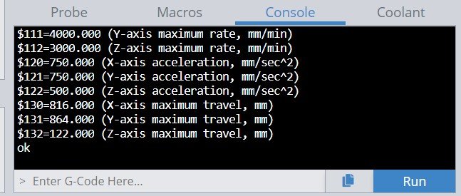
When you first start up gSender, the console will display EEPROM settings that are sent from the Arduino in the control box. These EEPROM settings control parameters for your CNC such as:
- Maximum speed and acceleration in each axis
- Boundaries of the work area
- Direction of each axis movement
- Limit switch settings
To access EEPROM settings again, enter in $$ into the console and hit the ‘Enter’ key or click the ‘Run’ button. These settings can be changed via the console as well as the Firmware Tool which we’ve designed as a much more visual way to alter machine settings.
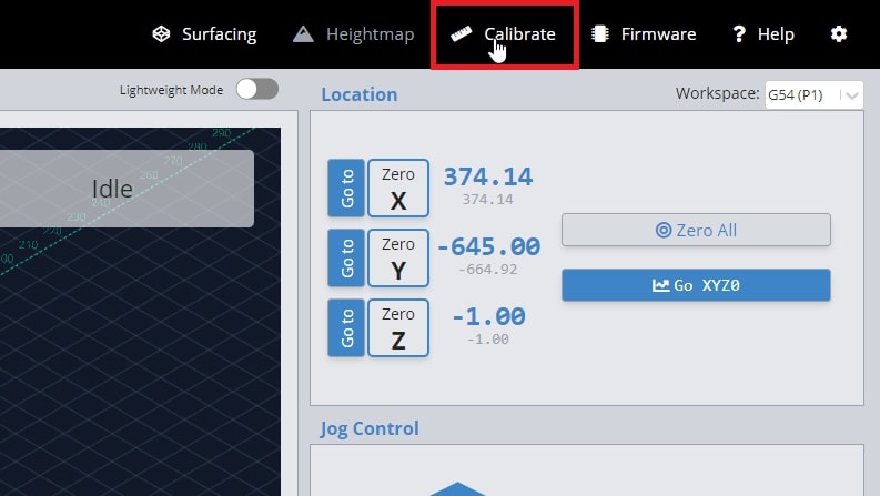
Calibrate Tool
The ‘Calibration Tool’ on gSender enables you to make finer adjustments to your machine for improved performance. There are three processes available on gSender:
- Diagnostics
- XY Squaring
- Movement Tuning
- Surfacing Wasteboard
Diagnostics
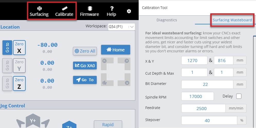
If you’d like to see general information about your CNC or are experiencing issues that you’d like to troubleshoot, gSender has a Diagnostics tool for that. Access it by clicking the ‘Calibrate’ tool on the top-right and opening the ‘Diagnostics’ tab.
Here you’ll see machine information, notable firmware settings, and at-a-glance status on whether your limit switches, touch probe, or other pins are activated. This can be handy if you’re encountering odd behaviour with certain machine accessories or to double-check your wiring.
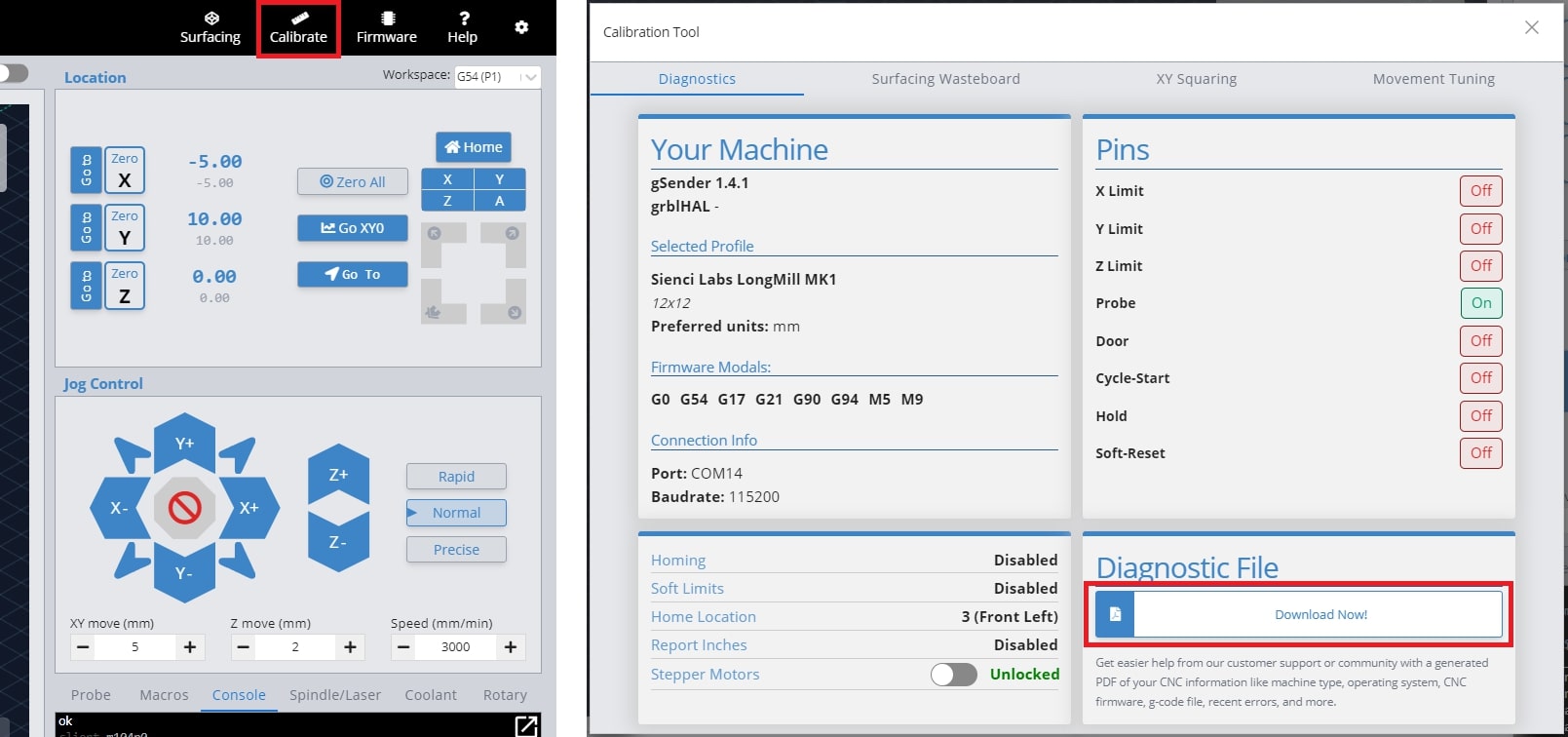
Another valuable feature is the ability to download a Diagnostic PDF file of your CNC machine when you click ‘Download Now!’. This PDF file is meant to include information on your computer, your CNC, recent alarms / errors, any currently loaded g-code file, and more. It’s basically a treasure trove of information that you can share on community forums, Facebook groups, or with your CNC customer support. This can go a long way towards getting help from others on diagnosing any problems your CNC might be experiencing.
To download the PDF, click the “Download Now!” button. This will open a save dialog box. Save the file to a location that you can easily access to send along to others in an email, support ticket or post online.
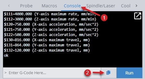
Lastly, you can copy the last 40 lines of code in the gSender console (1), by hitting the double page icon to the left of the Run button (2). This will copy the code to your clipboard, so you can paste it to forums or share it with support teams.
XY Squaring
When mounting your LongMill on the table, there is a basic squaring process illustrated in our instructions (https://resources.sienci.com/view/lm-table-mounting/). If you do find that the machine is not perfectly square, you can follow the steps in this process to fine tune the position of your rails.
When you access the ‘Calibration Tool’ window, the ‘XY Squaring’ procedure is shown on the first tab. All instructions are illustrated in the window, however a brief overview will be provided.
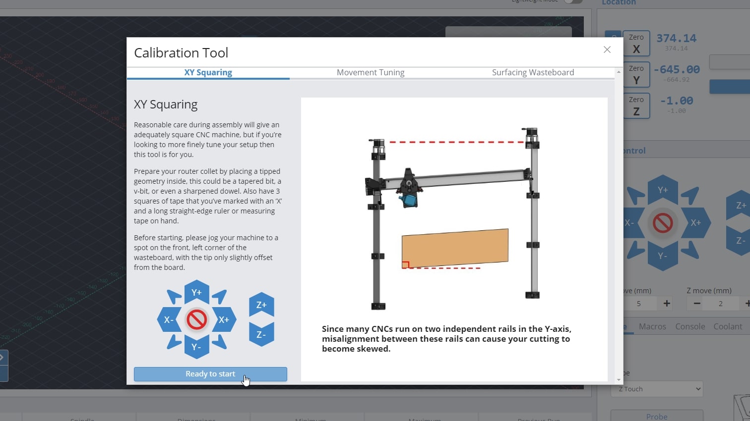
You will need the following:
- Ruler or measuring tape
- Tapered bit or V-bit
- Tape
- Jog the machine to the front left corner, with the bit raised slightly over the surface of your wasteboard
- Mark the points with tape and move the machine as directed
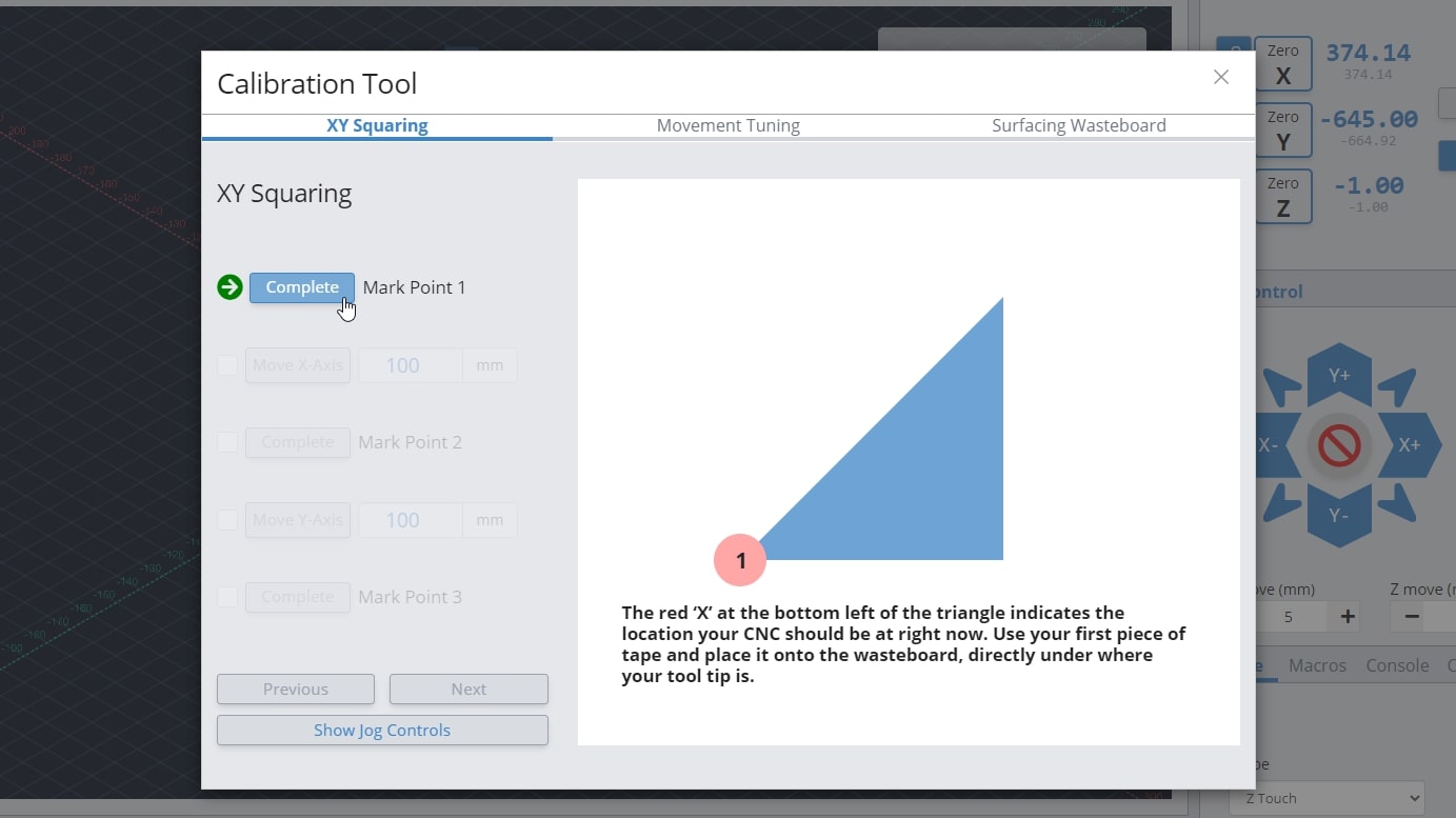
- Measure the distance between the marked points and record the values
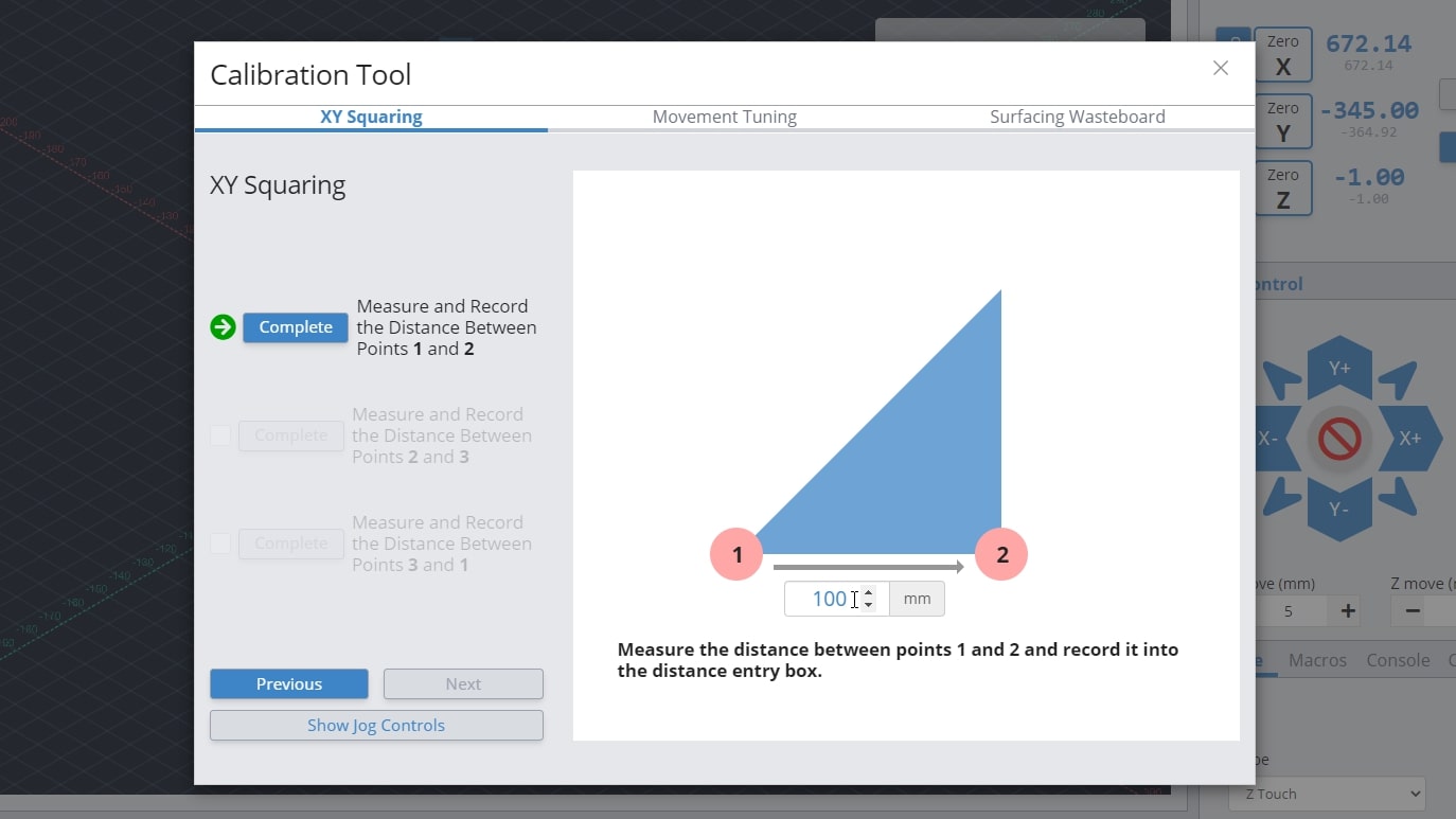
- Adjust your rail positions with the values determined by the XY Squaring procedure
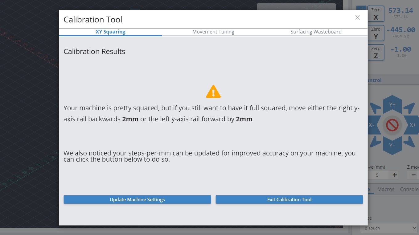
The great advantage to this tool is it saves you having to do the trigonometry yourself and will also let you know if your machine is aligned closely enough that it’s not worth worrying about.
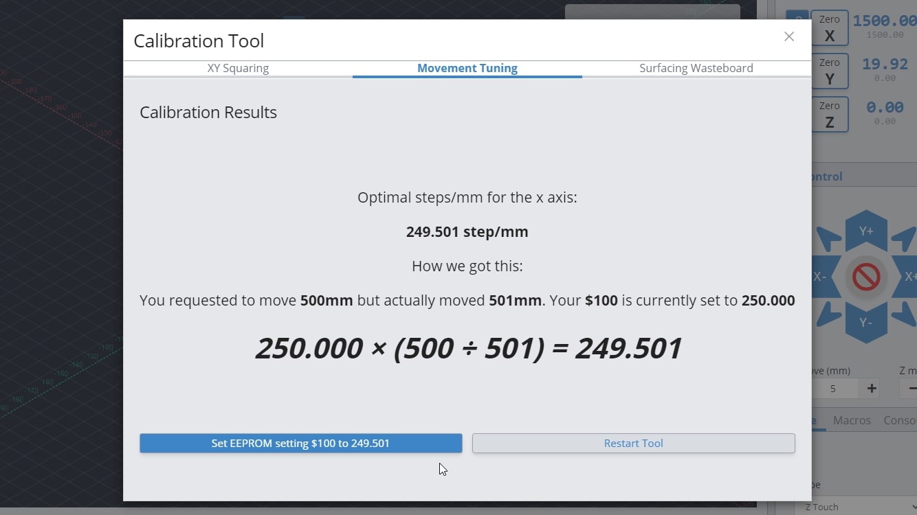
Movement Tuning
You are able to change how much your motors turn to improve the accuracy of your machine movement. This is done through modifying the EEPROM settings that are stored on your LongMill, which this process will guide you through. You can tune the X, Y and Z axes individually. All instructions are illustrated in the ‘Calibration Tool’, however a brief overview will be provided.
You will need:
- Marker or tape
- Measuring tape
- Jog your machine to the middle of whichever axes you choose to tune, so that there is enough room to complete this procedure. For example, on the X-axis you would jog halfway on the X-axis rail
- Select what axis to tune on the drop down menu
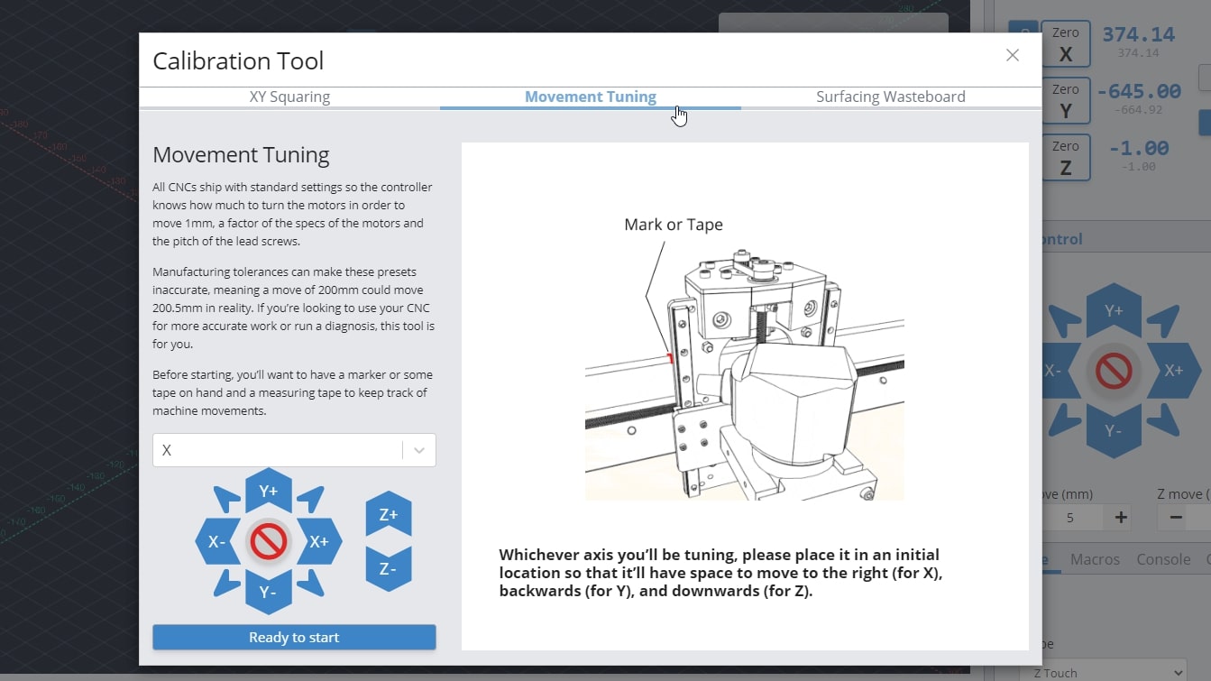
- Mark down the location of your reference on the machine. For example the X-axis tuning references the edge of the XZ gantry on the X rail
- Move the axis a chosen distance
- Measure the travel distance between the marked location and the reference edge
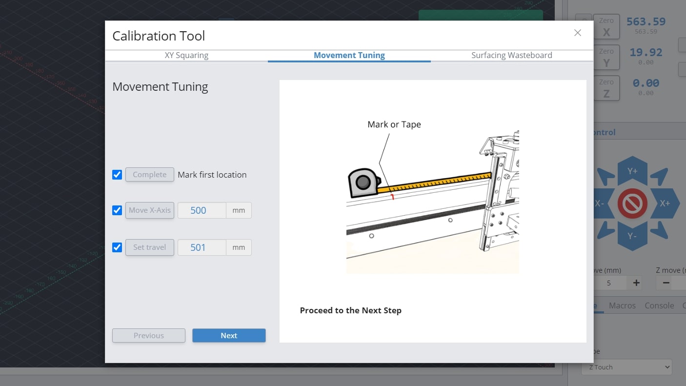
- Change the EEPROM setting as recommended by the procedure by pressing ‘Set EEPROM setting’
- Repeat the procedure for each axis you wish to tune
Surfacing
Surfacing the wasteboard of your machine can easily be done right inside gSender! The first thing you’ll want to do is decide where you want to start surfacing and in most cases the front, left of the machine is the most convenient. You might also want to remove any accessories that might get in the way of your machine travelling around during surfacing as well as have a good vacuum on hand because surfacing can get really messy. You can find the Surfacing Tool under the Calibrate tab, or under the Surfacing tab.
- Start by entering the settings you’d like to use to generate your surfacing job:
- X & Y: decides the cutting size (width and depth) you want to surface. If you’re surfacing your wasteboard, use the manufacturer’s spec on max machine travel or manually jog to the limits to cover the full cutting area, or if you’re surfacing a piece of material then you can use a measuring tape.
– LongMill MK2: 818mm (32.2″) or 1278 (50.3″) x 366mm (14.4″) or 866 (34.1″)
(if using limit switches, remove about 8mm/0.3″ in X and 11mm/0.43″ in Y)
– LongMill MK1: 320mm (12.6″) or 805 (31.7″) x 344mm (13.54″) or 844 (33.23″)
(if using limit switches, remove about 35mm/1.38″ in X and 24mm/0.94″ in Y)
(if using magnetic dust shoe, remove about 34mm/1.34″ in X)
– Mill One: 235mm (9.25″) or 257 (10.1″) x 185mm (7.28″) - Cut Depth & Max: describes how deep you want to cut per pass and the total depth you want to cut down. For larger surfacing bits usually you should keep cut depth below 1mm, max depth should be increased to a couple millimeters if you think your material is very warped.
- Bit (typically 6 – 25mm): make sure you have the right bit for the job like a surfacing tool or a large, flat end mill since this will give you a better surface finish.
- Spindle RPM (default 1700): only applies if you have an automatic speed control, otherwise set this manually on your router.
- Feed rate (default 2500mm/min): influenced by the RPM, step over, bit diameter, and cut depth. Luckily if you set it incorrectly you’ll be able to override it during the job since surfacing can cause burning when cutting too slow or can have worse surface finish when cutting too fast.
- Step over (default 40%): sticking around 40% tends to be a good balance between speed (using a higher %) and better surface finish (using a lower %).
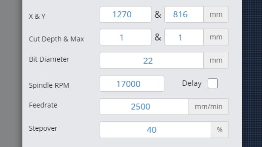
- X & Y: decides the cutting size (width and depth) you want to surface. If you’re surfacing your wasteboard, use the manufacturer’s spec on max machine travel or manually jog to the limits to cover the full cutting area, or if you’re surfacing a piece of material then you can use a measuring tape.
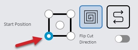
- Select a Start Position of any four corners or the center by clicking the dot; this is where the surfacing will begin. You can also select a surfacing pattern of spiral or zig-zag. The spiral will only cut from the inside-out if the start position is the centre. If you toggle the flip cut direction, the spiral will cut conventional instead of climb, and the zig-zag pattern will cut vertically instead of horizontally.
- Press ‘Generate G-code’ and check your surfacing tool path using the ‘Visualizer Preview’ tab. You can also see the raw g-code using the ‘G-code Viewer’ tab and can copy and save it to a g-code file if you’d like to use it again later.
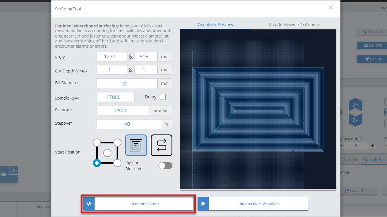
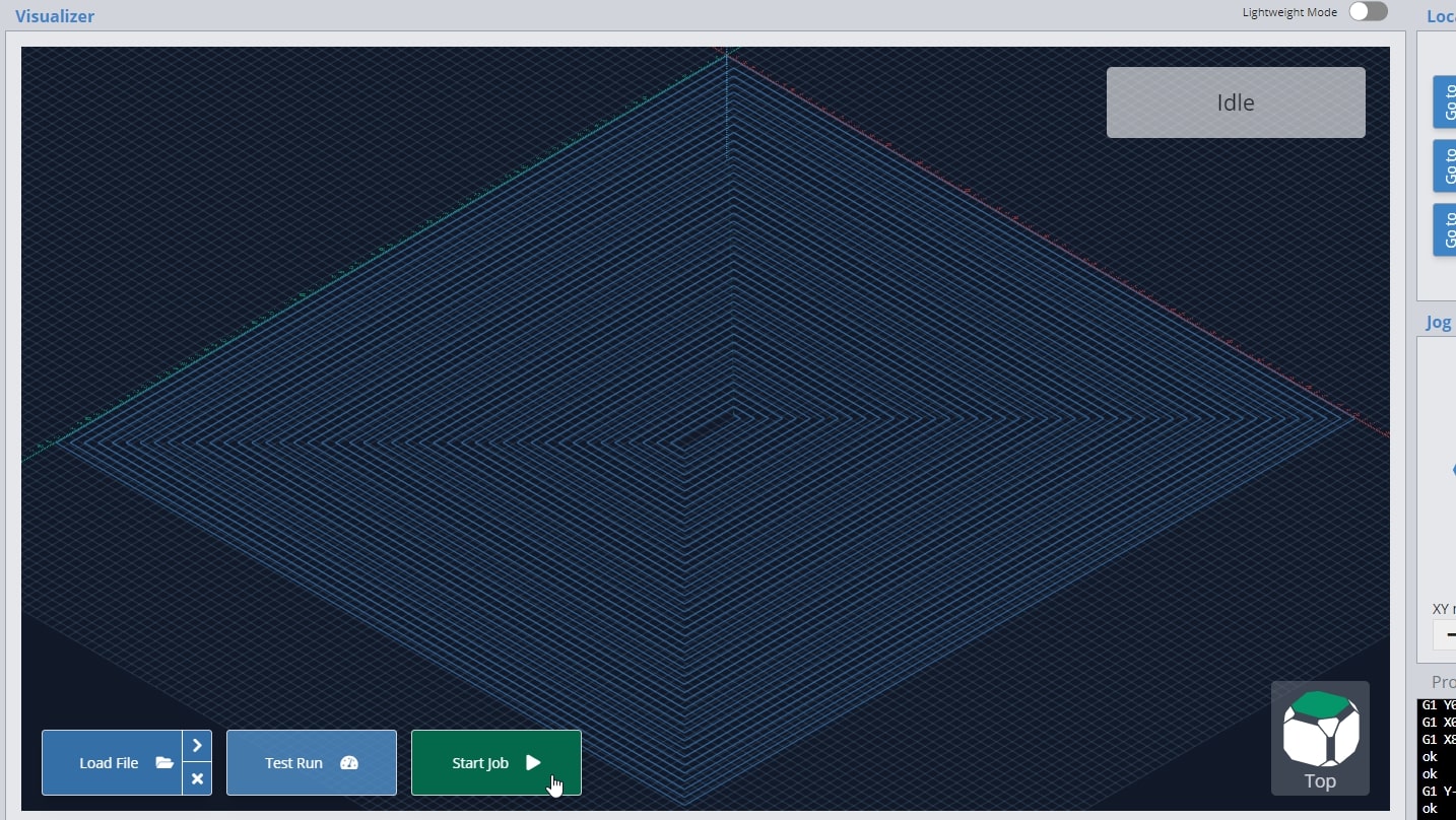
- Press ‘Run on Main Visualizer’ to bring the g-code into gSender’s main screen. Make sure that you jog to the starting point and set your zero in the right place before starting the job. You can also press the ‘Outline’ button as an easy way to check that you’ll be surfacing where you expect and if you find the dimensions aren’t correct you can always re-open the surfacing tool, tweak the size, and try again. Feel free to start the job whenever you’re ready!
Did you know that surfacing can be used for more than your wasteboard? It’s great for creating a perfectly flat surface of your starting materials, just like a jointer or surface planer would. You can also use the Rotary Surfacing tool if you are wanting round stock.
Job Stats and CNC Maintenance
Curious to know how many jobs you’ve completed, how many hours you’ve put on your machine or what maintenance you should be focusing on? Find this information in the ‘Job History & Stats’ section of Settings. Here you will find 3 tabs; Statistics, Job Table, and Maintenance.
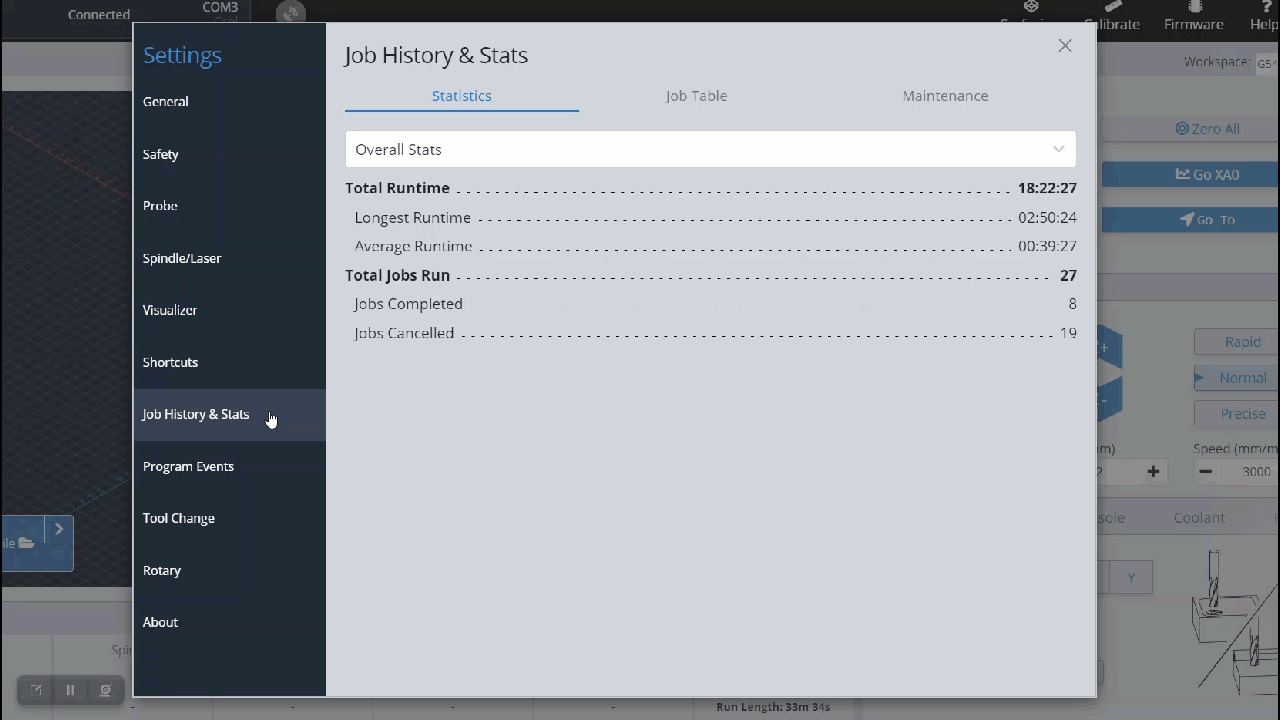
Statistics
The statistics tab has a dropdown menu that allows you to select between Overall Stats, Jobs Per Com Port (each com port is a different machine), and Run Time Per Com Port. These selections will show your statistics for total, average and longest runtime along with total, completed and cancelled jobs.
Job Table
The Job Table tab provides a simplified breakdown of each job, including the file name, duration of the job, number of lines in the job, the start date/time and completion status. This chart can be filtered by hitting the column header, or expanded to show more entries.
Maintenance
In the Maintenance tab, you will see preset tasks with an hourly countdown range, to remind you when a maintenance task is due to be performed. These times pull directly from the runtime of your jobs and allow you to mark them as complete to reset the timers. Once the task is in range, the maintenance is due, once past the range, the task becomes critical to address.
You can also add your own reminders, time due range and description to this section, to really make it your own.
Firmware Tool
Any board you have will come pre-installed with CNC firmware, along with the custom EEPROM settings for that machine, so typically you won’t need to access the ‘Firmware’ tool. If you choose to use this tool, it can give you access to many of your machines “behind-the-scenes” settings for tweaking or modding your setup. Open it by clicking the ‘Firmware’ tool at the top of the screen.
Unsupported CNCs
If your CNC isn’t listed below, then it’s considered “unsupported”:
- Sienci Labs LongMill (MK1, MK2, and MK2.5), AltMill, and Mill One (V1, V2, and V3)
- Don’t see your machine on this list and want it fully supported? Let your manufacturer know to get in contact with us so that we can add their machine profiles to gSender 🙂
If your machine is unsupported, it means that the Firmware Tool won’t be able to perform the same features as for supported machines. In this case, if your machine isn’t working, contact your manufacturer to get their advice on how to fix it. Using this tool makes it possible to ruin your machine further and we won’t be able to help you with your specific hardware. For unsupported machines:
- Choosing your machine name from the drop down menu is primarily cosmetic
- Flash either vanilla grbl, or for grblHAL boards upload a hex file to flash a new firmware
- Import EEPROM settings from a file if you had settings that were working and something changed
- Export current EEPROM settings if you’d like to save your current setup in case something goes wrong
- Restore all your machine settings back to typical vanilla grbl values
- And otherwise see and modify any machine settings as well as search any keywords to help you find what you’re looking for
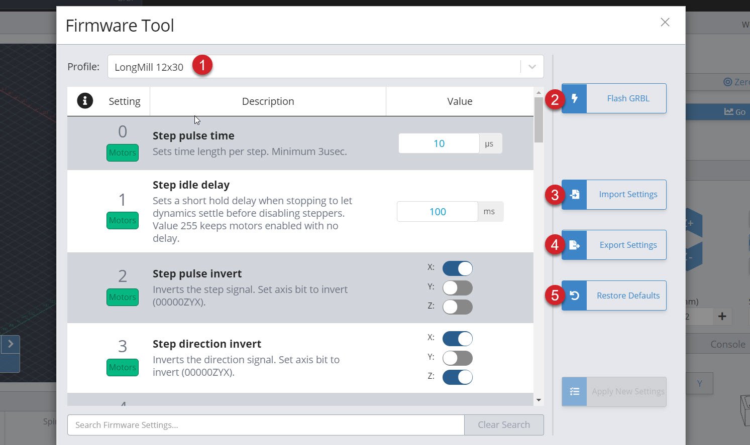
Supported CNCs
If your CNC was listed above then it’s “supported” by the Firmware tool. This means that the manufacturer is working with us to keep their machine profiles up-to-date, which in-turn gives you access to more features:
- Choose your machine name from the drop down menu
- Flash either your specific machines grbl firmware, or for grblHAL boards upload a hex file to flash a new firmware
- Import EEPROM settings from a file if you had settings that were working and something changed
- Export current EEPROM settings if you’d like to save your current setup in case something goes wrong
- Restore all your machine settings back to the defaults for your profile in case they’ve somehow been altered or wiped (like a “factory reset”)
- Also be able to see a yellow highlight and be able to reset individual settings that have been changed from the machine defaults
- And otherwise see and modify any machine settings as well as search any keywords to help you find what you’re looking for
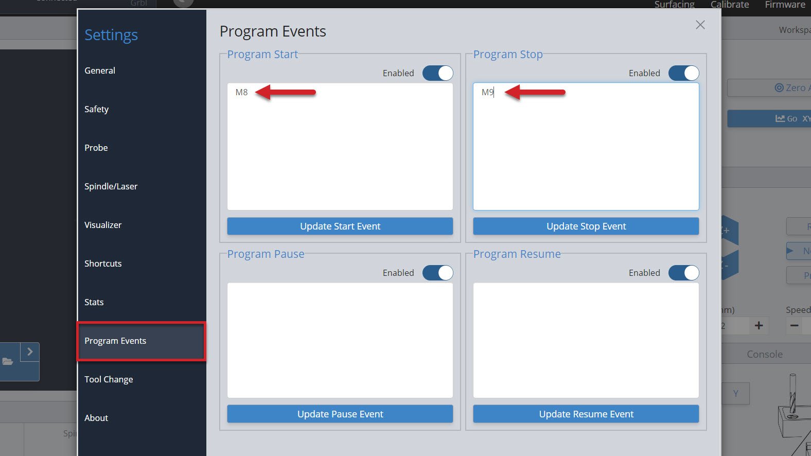
Start/Stop G-code
A powerful feature to control your accessories automatically (like turning on/off a spindle or vacuum) or to run movement macros that are custom to your machine. ‘Program Events’ (formerly “Start/Stop G-code”)’ in gSenders settings automatically apply g-code to your cutting job at the start, end, or if you stop, pause, or resume the job. The ‘Stop’ event is there to ensure that “ending g-code” is always run even if you have to stop a job prematurely. You can also toggle these on and off if you don’t want them run for specific jobs.
Three massive perks to setting up automations this way are:
- There’s no need to get into the weeds customizing your CAM post processor
- gSender is able to send code when you pause, resume, or emergency stop your machine, all of which a g-code file on its own would never be able to do
- This additional amount of control will make your CNC safer to use
For example, if you were to add M3/M5 commands to your CAM post processor to control your spindle but then chose to pause your job midway to check something, then most CNCs wouldn’t know to stop spinning your spindle or retract it since g-code files can’t carry this information; this is where gSender is able to the heavy lifting.
For the text-box of the situation you want the action to happen, type in the g-code commands you wish to run, then press the ‘Update‘ button to save it. For example, if you installed an IOT relay to turn your router and vacuum on and off and wanted to make sure they were enabled for every job you ran, you could add:
- “M8” for Start and Resume
- “M9” for Stop and Pause
- If you wanted to add a delay to give your vacuum or router time to fully turn on, then you could add “G4 P5” after the M8 for a delay of 5 seconds (you can customize that delay to your equipment)
- If you wanted to keep the vacuum and router running during a pause, then you don’t need to add “M9” to Pause
- All this can also apply to automatically control a spindle, where you’d instead use “M3” and “M5“, you can also add a delay with “G4 P#“
- If you want to raise the Z-axis on Pause and lower it on Resume, you could also add:
- “%global.move=modal.distance” then “G91 G0 Z-5” for Pause to move 5mm out of the way
- “G91 G0 Z5” then “[global.move]” for Resume to move back down
Tool Changing
For CNC machines, tool changes are pauses that are programmed in the g-code for a user to switch out the cutting tool for a different one, or the machine to do that automatically. The workflow can also sometimes involve pausing until the user tells it to continue, usually through a ‘Resume’ and/or ‘Confirm Tool Change’ button on the machine interface. This allows you to run multiple toolpaths (cutting operations) within one g-code file.
The g-code for tool changing is an M6 command. gSender is quite capable when it comes to customizing CNCs for tool changing, even having full Wizards built-in. The tool change options are in the Settings ➜ Tool Change menu. You can select from one of 6 different options, and even choose to ‘passthrough’ the M6 and T commands to the CNC controller for CNCs that are capable of handling tool changes on their own.
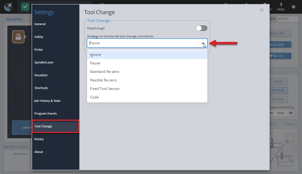
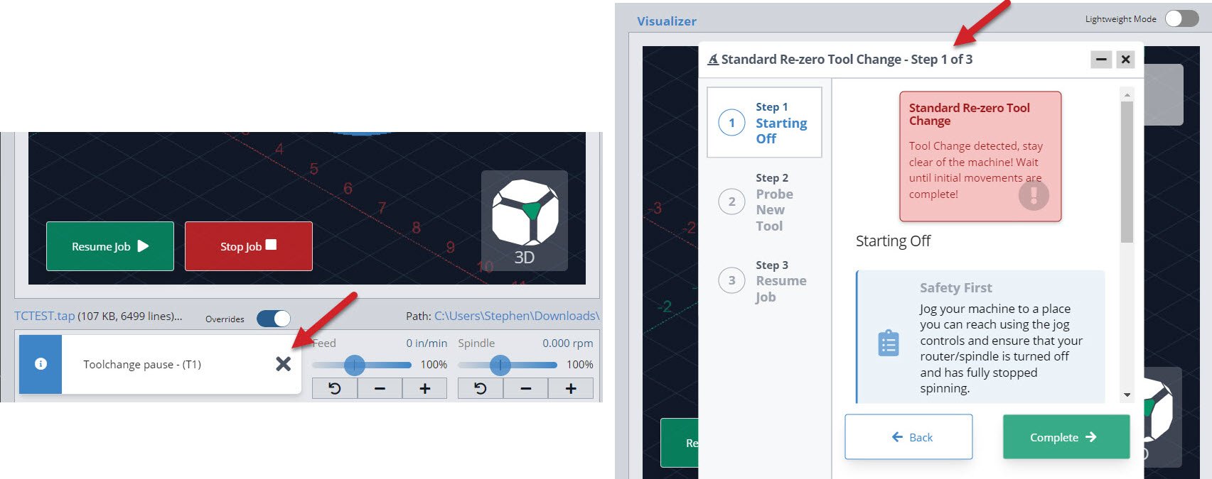
You can Ignore any M6 tool change commands, Pause the job when a tool change is recognized, or select one of the last three Wizards that will guide you through pre-set tool changing methods. In the split image below, you can see an example of the job Pause on the left side and the Wizard on the right.
If you are using one of the wizard options, know that you can access all other gSender controls while the wizard is open like jogging and zeroing. It also has flexibility to go back a step if you missed something or had a mistake, or to be minimized temporarily if you want to check the visualizer.
- Ignore
This simply ignores any M6 commands in the g-code file. This is the default option since it’s perfect for beginners that only make projects with one tool or those that create separate files for each tool and prefer to manually perform tool changes between files. - Pause
Pauses gSender at the tool change point, as if you had hit the pause button manually. This gives you freedom to jog, zero, or anything else you’d like, and is great for those that are running multi-tool files but want to use a different process than the Wizards provide. This could be a manual probing process, a different tool changing approach, or running custom macros to support your machines specific hardware. gSender is compatible with tool length sensors like the Carbide 3D bitsetter, and our community has compiled a list of macros for tool changing that you can use when you are paused. Just note that pausing can’t always guarantee keeping track of your movements and actions when it comes time to resume the job so try to ensure you get back to the starting point and set zeros correctly. - Standard Re-zero (Wizard)
Titled ‘standard’ because it’s exactly the same as the standard process you might normally follow for running a file, changing the tool, re-zeroing Z, then running the next file except it’s applied to a single file with multiple toolpaths. Since the process is so familiar, this is a great way to dip your toes into tool changing within one file. Compatible with using a touch plate or the paper method, zero out at a predetermined spot (usually at the front left corner), and use jogging to move around. The advantage of introducing this extra automation and guidance during tool changes is that you don’t have to worry about custom macros and it reminds you of simple steps like turning the router back on or zeroing Z. - Flexible Re-zero (Wizard)
Similar to the ‘standard’ wizard with similar steps and manual movements but provides the ability to zero Z off a point that wasn’t your starting Z when it comes time to change the tool. This is useful if you tend to carve away your material and lose the starting Z or you don’t have limit switches but would like a process similar to a tool length sensor. -
Fixed Tool Sensor (Wizard)
This is the most automated setting where all probes and movements are done for you, you only need to intervene by changing the tools. Set up the job and zero normally then expect the machine to move to the sensor location when it reaches a tool change, verify tool length, prompt for a change, probe new tool, then resume cutting. Your machine will need to be homed, have limit switches, and have a tool length sensor (compatible with Carbide 3D bitsetter for example) in order for this option to work. To set up the sensor mount the router/spindle as far down as you might typically put it, with the longest bit mounted in it, then jog it to hover over the tool length sensor with some room to spare and open the settings menu to save that location. This will be the spot your machine moves to every tool change so if it’s too low or your sensor doesn’t work it’ll run into the sensor.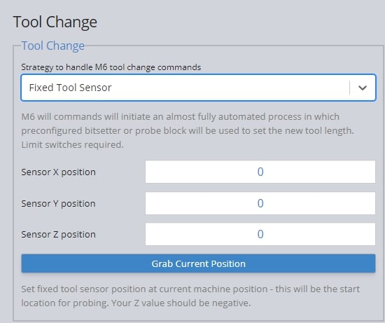
-
Code
You can enter your own macros before and after the tool change with this strategy selected which is fairly powerful for making tool changing processes that are more automated than just pausing.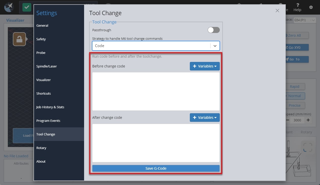
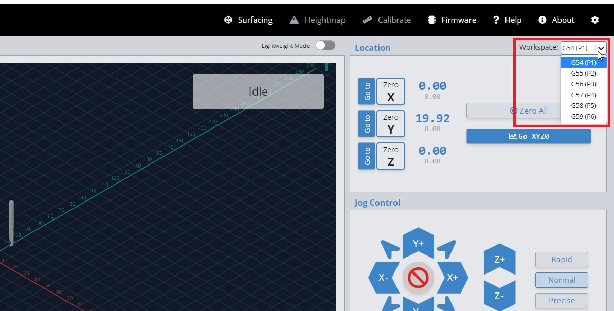
Workspaces
Usually you would only have one origin or zero position for your project, therefore gSender will only save one zero. However, if you plan to do a series of projects that require different zero positions, or are lining up to do some more complex jigging or part batches, you may want to set up multiple workspaces all at once. This can save you time by not having to set a zero position for repetitive tasks or specific jig setups. You can do this by creating up to six different zero positions with the six workspaces in gSender. Access each ‘Workspace’ at the top right of the program by pressing the drop down to select which workspace to use. gSender will act completely in-line with whatever workspace you’ve selected, whether you want to set zero, probe, surface, or anything else.
The video below explains the process in greater detail. If you’re coming from a more technical background, you’d usually call these ‘workspaces’ G54, G55, G56, … G59.
Settings
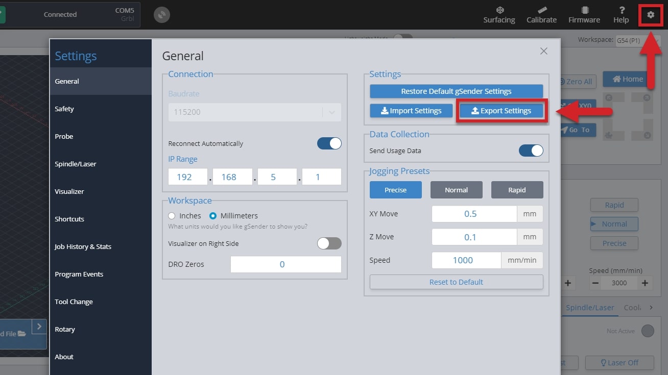
Transferring Settings
gSender’s settings are stored on a file on whatever computer is used to run it. This mostly includes everything that you’ll find in the settings menu such as units, machine preset, probe, tools, jogging presets, keymapping, tool change g-code, start/stop g-code, and more. If you plan on using a different computer to run your CNC using gSender or want to run gSender remotely, some of these settings might be very important to carry over to the alternate computer to make sure things keep running as expected.
To transfer your settings over:
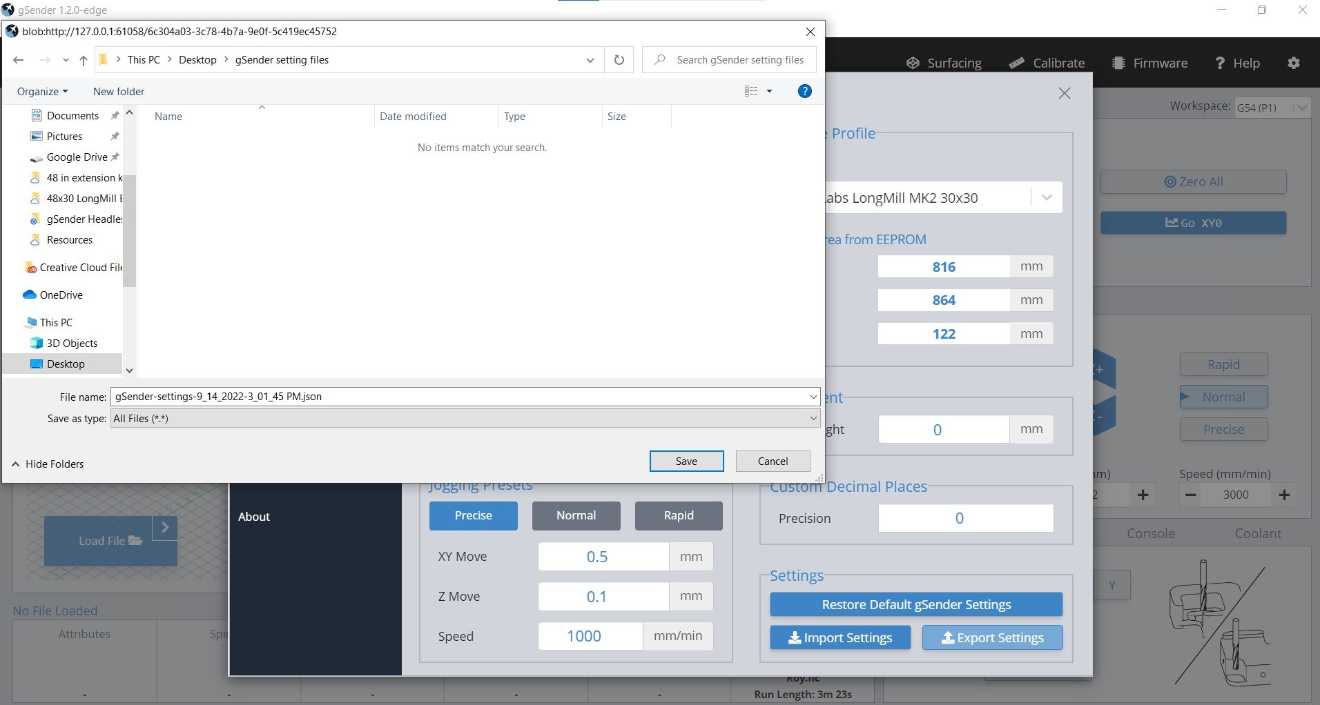
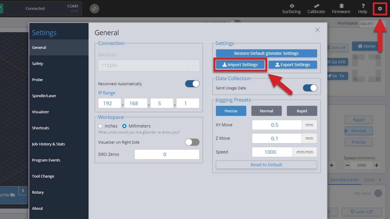
- Begin by opening gSender, going to the settings gear in the top-right corner, and clicking the ‘Export Settings’ button in the ‘General’ tab
- Save the file somewhere onto your computer that you can find afterwards
- Outside of gSender, find the file and transfer it using a memory stick or sending it over the internet by emailing to yourself or using Google Drive or OneDrive.
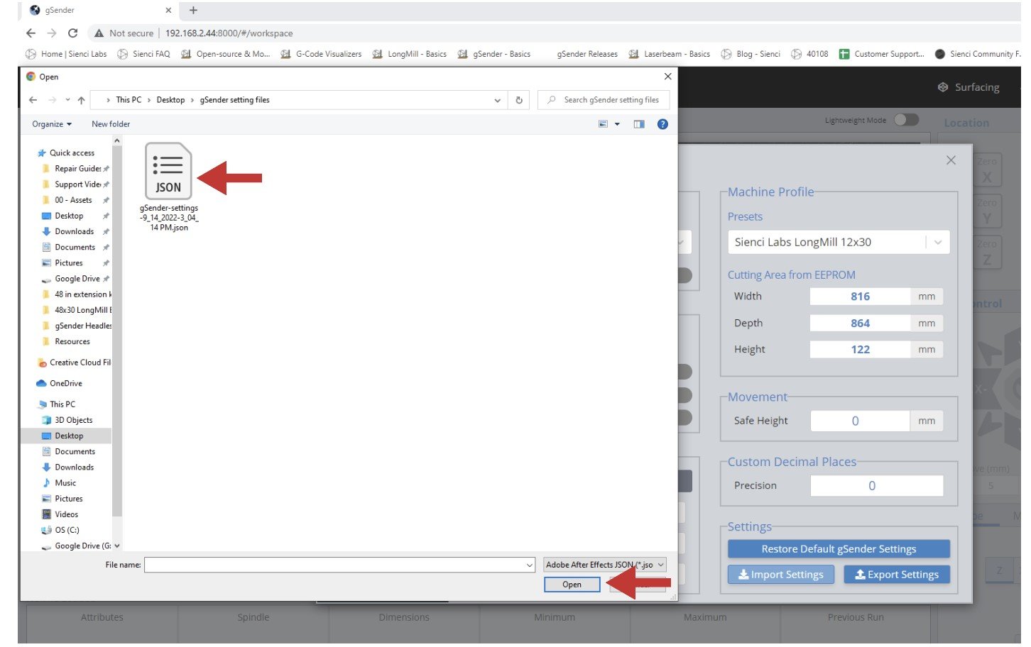
- Once you’ve got the file onto the other computer it’s now easy enough to open gSender on that computer, or in the web browser if you’re doing remote control, and go to the settings and click the ‘Import Settings’ button in the ‘General’ tab.
- Locate the file and click ‘Open’
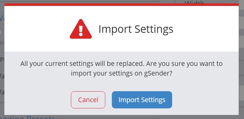
- You’ll get a warning. Click ‘Import Settings’ if you want to continue. Once you do, gSender will disconnect and you’ll need to reconnect the machine to resume operation but the settings should now be brought over.
Remote Mode
If you’ve ever wanted to run your CNC without being stuck right next to it, this is the feature you’re looking for. The remote mode is exactly how it sounds, it gives the ability for a remote computer to connect over a shared internet network to a permanently installed, normally lower-end computer, that runs the CNC. This ‘remote computer‘ can be any device that can connect to the internet and run a web browser, meanwhile the ‘inline computer‘ plugs into your CNC with a USB cable and will receive commands over the internet from the remote computer.
This feature is handy if you’d like to:
- Load in a file from your design computer outside your shop then run it on your computer inside the shop
- Use a tablet as the primary means of controlling your CNC rather than a mouse and keyboard
- Use a phone for occasional use when jogging or running functions
- Leverage a mini PC or Raspberry Pi as the inline (tethered) computer for cheap, fanless, and reliable operation without taxing them with a display, keyboard, and mouse
Before diving into the setup, here are some quirks and warnings that are important to keep in mind:
- Both systems need to be on the same internet network to work, where the device used to run remote operations needs to be able to run a web browser
- You may need to be an Administrator of the inline computer to make the changes needed so ensure you have that power
- This feature will always be inherently less reliable than a hard-wired connection because of its reliance on your shop’s internet connection for communication. Keep this in mind if you intend on using remote control for more important projects or with expensive tools or materials
- Remote control is still in development so expect to experience some bugs if you’d like to set this up for yourself. The setup process is a little bit more involved on your computer so we don’t advise using this feature if you’re not confident with troubleshooting your own setup
- This feature is NOT intended to enable use of your CNC while AWAY FROM YOUR WORKSHOP. A CNC should always be run while you or another knowledgeable operator is in the vicinity to ensure safe machine operation and be able to react if intervention is required. CNCs can cause fires from electronics, material friction, and can have other safety hazards if not properly monitored
- In other contexts this feature could be thought of as running ‘headless’ but it doesn’t fully meet the requirements of that term. Though remote controlling the CNC from another computer should reduce the requirements of the inline computer, at minimum it still needs to boot the idle version of gSender with a window manager. This is in contrast to a fully ‘headless’ setup where a skinned-down program exists only to pass along information from other devices with no UI to send along information itself
Enabling Remote Mode
All setup steps need to happen on the inline computer (the computer you’ll have connected via USB to your CNC) and have been simplified to mostly happen within gSender.
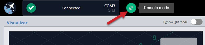
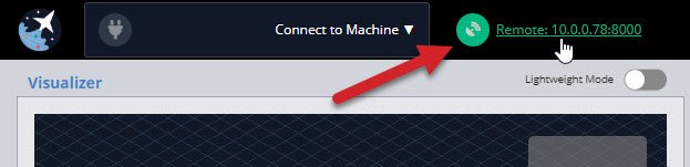
- To begin, click the satellite antenna icon on the top right of the screen. If the icon isn’t there, you’ll need to make sure you have a newer version of gSender that supports this feature.
- This is where remote mode is set up. First you’ll want to click the ‘Enable Remote Mode’ toggle. Second, click the box next to ‘IP’ and select one of the options that gSender tries to recommend for your particular computer network. For an average setup the ‘Port’ value can also be left alone. The third step is to click on OK once you have completed the configuration. You can also use your camera to scan the QR code, and be taken directly to your remote interface!
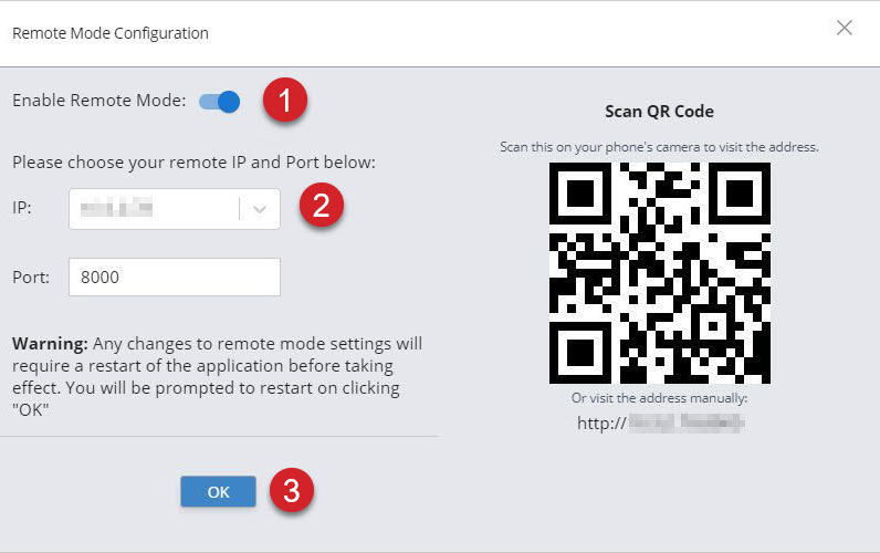
If you’re an advanced user or have tried the default values without success, you can type in any other IP address or Port that you’d like since the defaults aren’t guaranteed to work. Common port values are 3000, 8000, and 8080 and generally don’t go below 1024 since those are considered privileged. Changing IP addresses can also help if you’re running a VPN or need a different internal IP to external IP mapping.
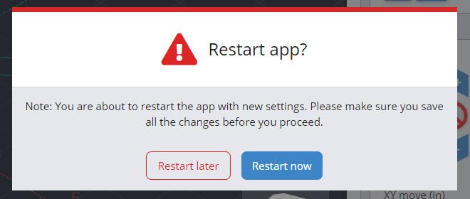
- gSender needs to restart in order for the remaining changes to take place. You can choose to restart immediately or wait until later.
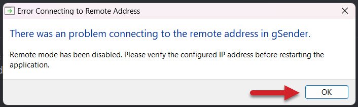
- If there was a problem using the specified IP address or Port, you’ll get an error window to let you know. In this case you should be able to reopen gSender, go back to the Remote Mode settings, and try another IP or Port until the setup is successful.
- You’ll know the setup was successful if gSender restarts, the antenna icon is green, and numbers show next to it. As a quick test, click on the numbers to copy them then open a web browser like Chrome or Edge and paste them into the address bar and press enter (you can also type the number manually). After the page loads, you should see a copy of gSender running in the web browser! If something’s not working, check you followed the setup steps correctly or reference the firewall or troubleshooting sections below.
Firewall Setup
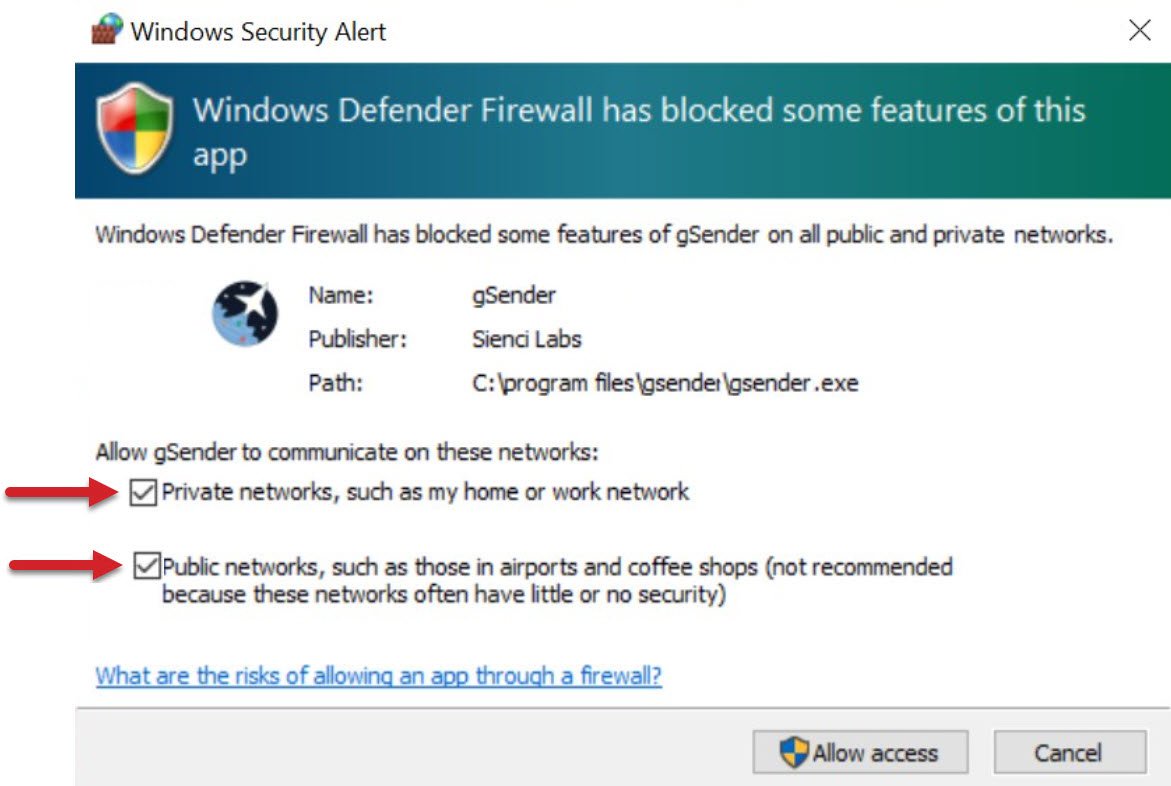
During initial setup, you might see a Security Alert window pop up or run into an issue where the browser address isn’t working. The most likely issue here is that your inline computer firewall isn’t allowing gSender to communicate to other devices on your network.
For Windows: You should simply see a popup from Windows Firewall or your antivirus software asking for approval to allow gSender to communicate on your home network. Please check the box beside “Private networks” and “Public networks”. This should be all that’s needed.
For Mac / Linux / Pi: If you find that you can’t connect with outside devices or just want some extra safety you might want to try opening the Universal FireWall (UFW) on a given port to allow external access. This can be started with sudo ufw enable (if UFW is not found then install it using sudo apt-get install ufw and your root password) then opening the desired port, for example sudo ufw allow 8080 opens port 8080 for external access. If you want to see what ports are already open, you can use ufw status verbose.
Using gSender Remotely
With setup complete, regular use is pretty straightforward:
- Connect the inline computer to your CNC as you would normally using the USB cable. Turn on power to your CNC and connect to it in gSender as usual.
- Look for the numbers next to the antenna and write them down including all the symbols and punctuation; these will be used to connect to your CNC on the remote computer / device.
- On any remote device that can run a web browser like Chrome or Edge (computer, phone, tablet) open the browser and type those same numbers you wrote down into the top address bar. In this example the numbers are 192.168.2.203:8000 but yours may be different. Press enter, and hopefully the familiar gSender interface will appear in your browser window. If not, ensure that your remote device is on the same network as your inline computer.
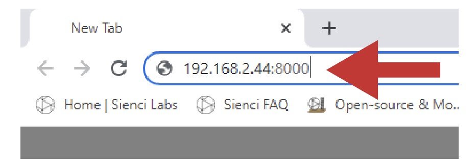
- Once connected, you should now be able to control your CNC remotely with most of the same features and functions you’d normally expect:
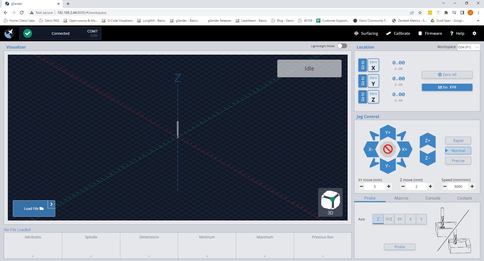
- You’ll be able to use both the remote and inline devices simultaneously to control your CNC like jogging, opening and closing files, probing, macros, and more
- You’ll also see that both their screens look exactly the same so you can watch the visualizer move around or check on the machine state
- On phones the screen will look different since we’ve optimized it for jogging, setting zeros, and probing
- When you click to ‘load a file’ you’ll see that you’ll only be able to load files from the device you’re currently on, don’t expect to gain access to the files stored on the opposite device. However once the file is loaded into gSender, you’ll be able to run it from any device
- There can be multiple remote devices all connected to the same inline computer at the same time to control your CNC from multiple devices. There can also be multiple inline computers controlled from the same remote computer, giving you multi-CNC control from the same device
- gSender settings like ‘safe height’, ‘start/stop g-code’, ‘tool changing’, and any other gSender specific settings won’t carry over to the remote computer. If you want to make sure files are run the same way every time you’ll need to transfer your gSender settings over by following the ‘Transfer Settings’ instructions below
- If you’re using your phone, save the unique URL to a bookmark on your home-screen so you can open Remote gSender easily every time! Check out this video for details
Troubleshooting
If you ran into issues during remote control setup, here are some other checks you can make:
- The easiest checks to make sure remote mode works for you is to make sure you have gSender open, you have gSender connected to your CNC, and you’ve turned remote mode on
- Double-check your remote mode configuration menu, antenna icon, and IP address are showing on the inline computer
- Ensure both your computers / devices are on the same internet network and the IP numbers match on both devices
- Double check you took the right steps in the Firewall Setup section. Your inline computer might be blocking gSender’s ability to send information to the internet because of the firewall. On Windows, follow these steps to modify the firewall:
- Click Start and open your computer’s Control Panel
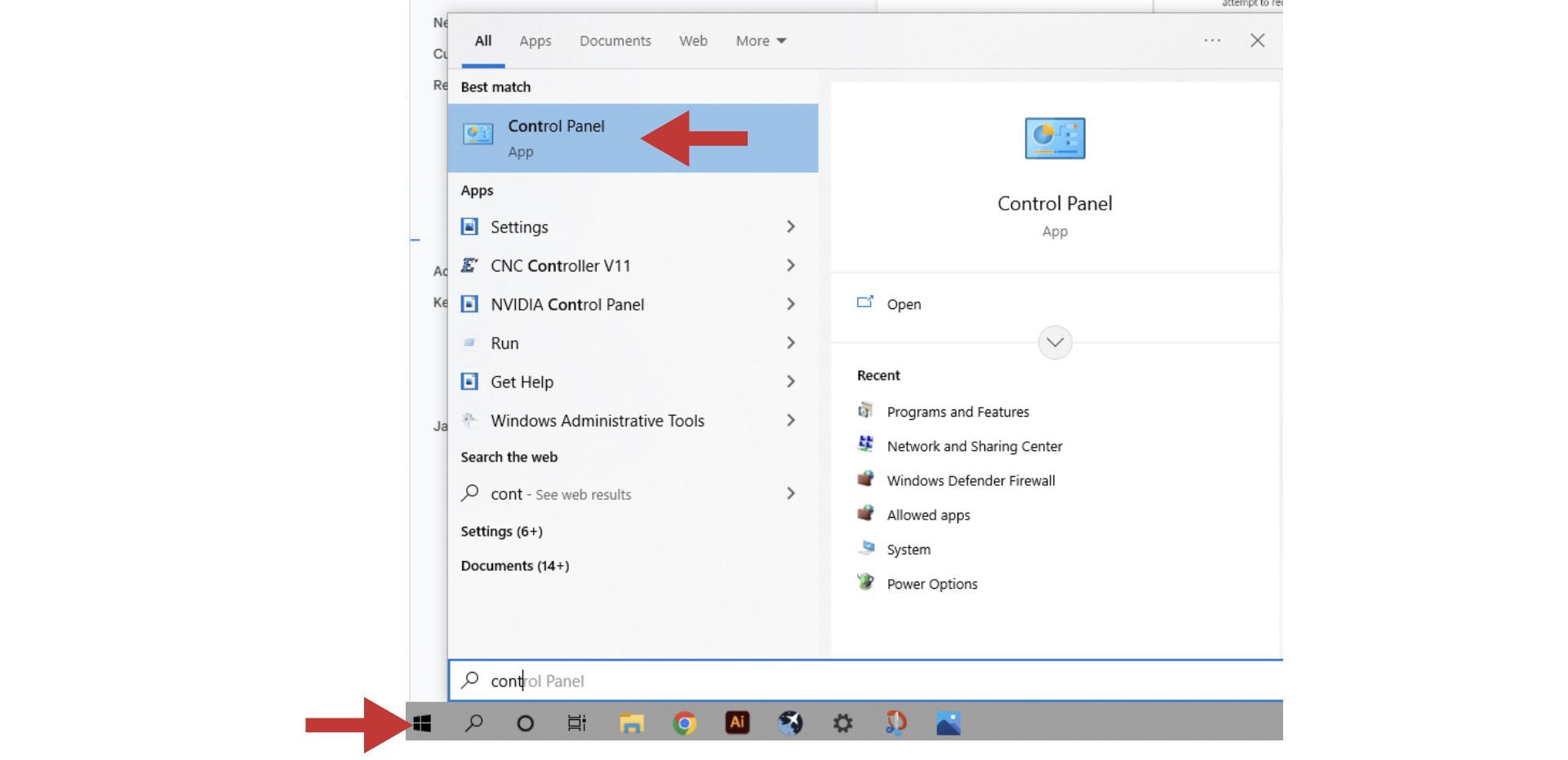
- Open the ‘System and Security’ settings
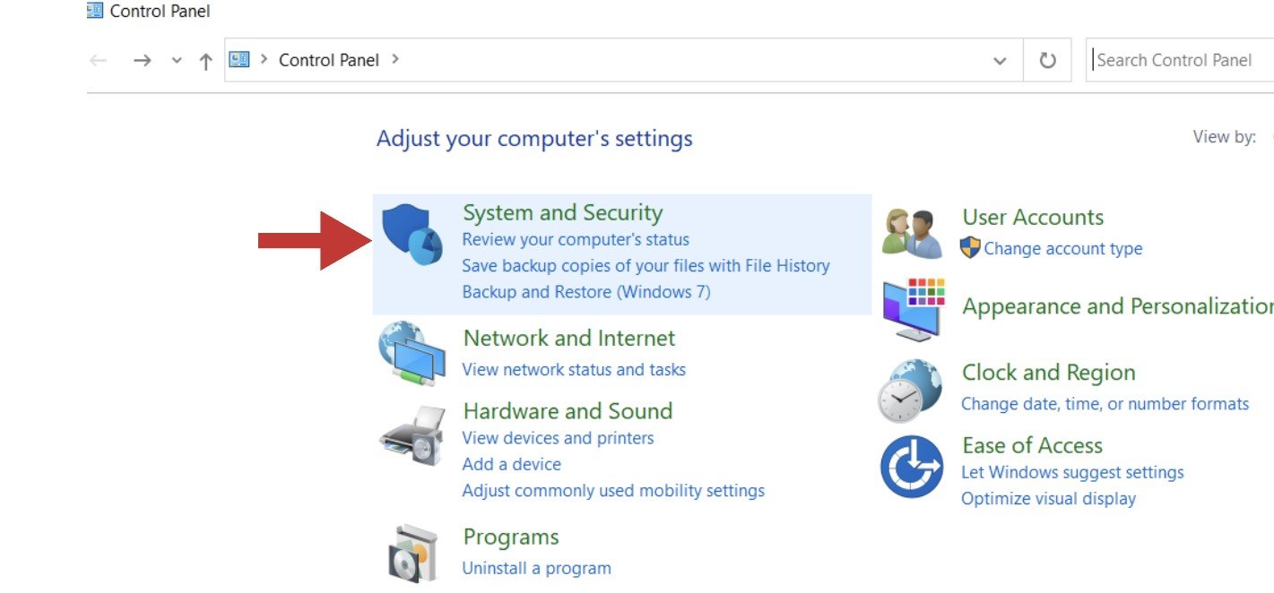
- Open the ‘Windows Defender Firewall’ and go to its ‘Advanced settings’
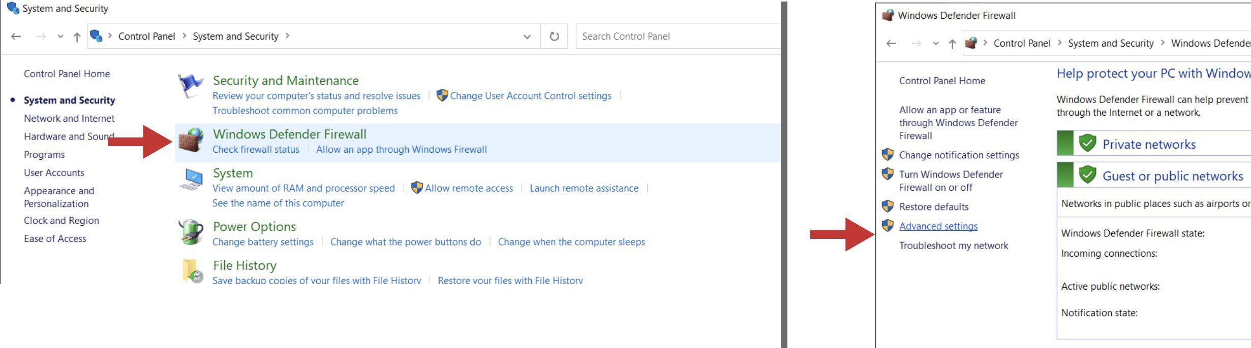
- In the column on the left, click on ‘Inbound Rules’ and then find and double-click on ‘gSender’. There might be three options of gSender to click on, you’ll want to click on the version that has the word “All” under the ‘Profile’ column
- In the pop-up box, click on the tab labelled ‘Protocols and Ports’. Next to ‘Local port:’ you’ll want to use the drop-down menu to select “Specific Ports” and then type in the default port of “8000”. If you have added a custom port to gSender’s Shortcut properties, you’ll need to type in that number instead. Once you hit ‘Apply’, you can check to see if this resolved your problem.
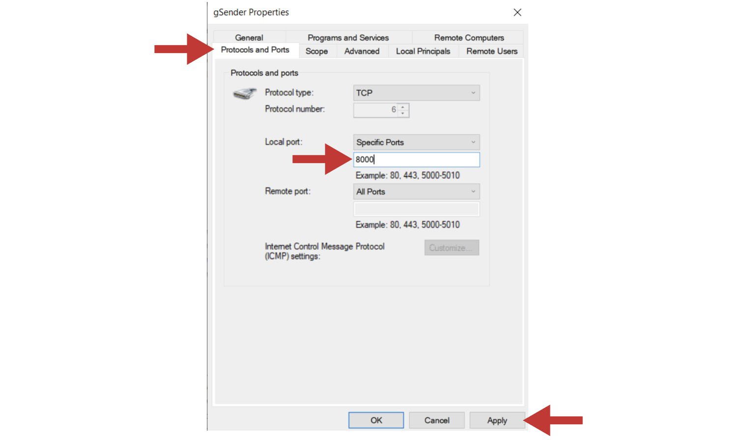
- Click Start and open your computer’s Control Panel
- If when gSender reopens you’re met with a white screen, this means an error has occurred that we weren’t able to detect. This is rare, but unless we can find some other way to manage this the only fix is to uninstall gSender and reinstall it again.
- If on the remote device you get a popup for “Server Connection Lost”, this indicates that either gSender on the inline computer was closed or the shared internet is disconnecting. You should be able to fix this by restarting gSender on the inline device, then clicking “Attempt Reconnect” on the remote device.

Rotary
gSender has a unique ability to control a rotary axis on normal, 3-axis grbl machines. We call this “rotary mode”; which isn’t to be confused with grblHAL machines where gSender by default supports full, 4-axis motion. The idea is that once you’re in this “rotary mode”, gSender does the legwork to swap firmware settings over to your rotary setup, translate A-axis movements to your machine as if they were Y-axis movements, and as long as you’ve done the legwork to align and swap over your wires then your rotary A-axis should now be good to go!
Rotary Mode
Navigate to the Settings where you will find the Rotary settings. Here you can toggle the Rotary controls to make them visible on the main page.
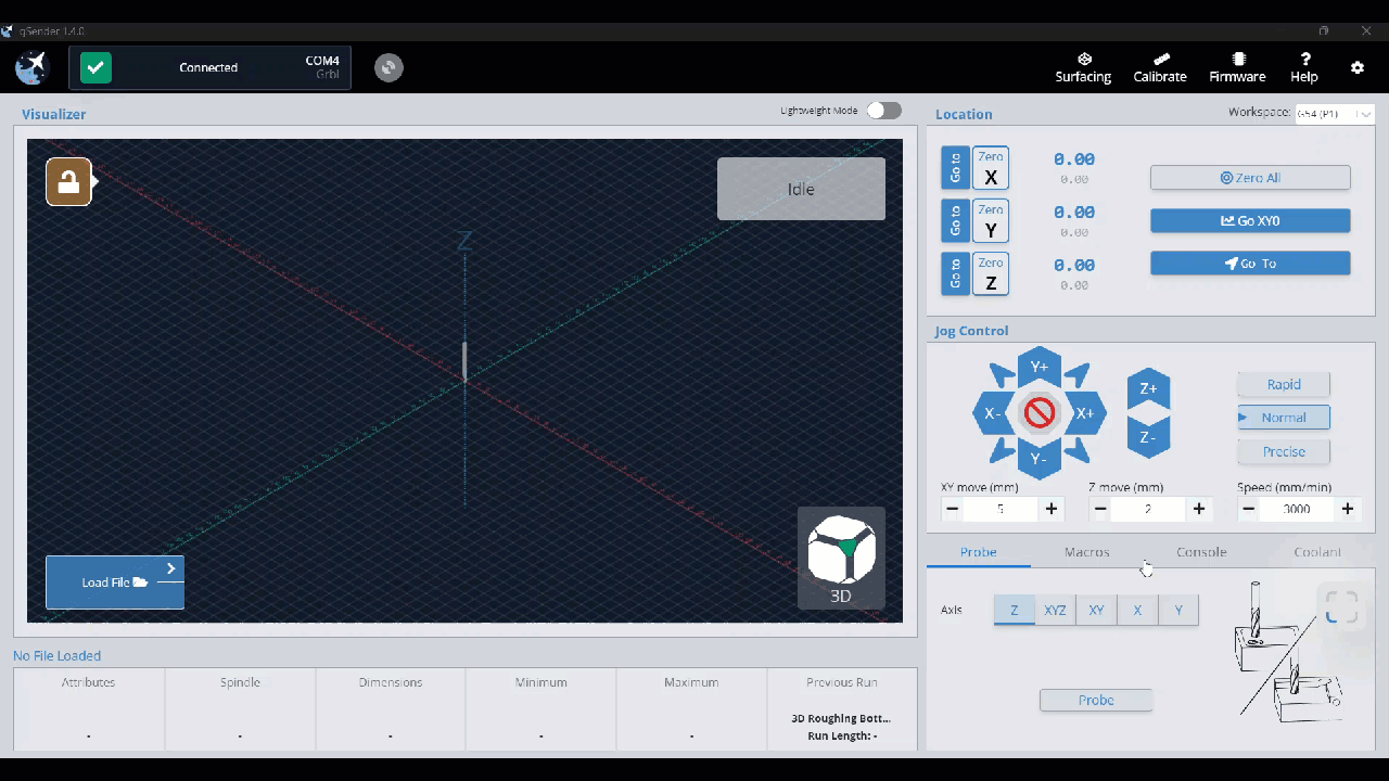
Once the toggle has been turned to display, you will see an additional tab at the bottom right of the window, called Rotary. With this tab you can:
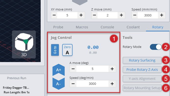
- Jog Control – Rotate the A-axis, go to Zero, set Zero, and adjust speeds
- Rotary Mode – Toggle into Rotary Mode
- Rotary Surfacing – Wizard to turn square stock round
- Probe Rotary Z-axis – Automatically probe to find the Z-axis
- Y-axis Alignment – Automatically probe to align the Y-axis along the A-axis (Turn rotary mode off to access this feature)
- Rotary Mounting Setup – Drill holes in your wasteboard to mount our own Vortex Rotary track (Turn rotary mode off to access this feature)
Note: Before switching to rotary mode, using the jog controls, rotary surfacing, or any other rotary actions, you’ll need to check that you’ve got your rotary set up and positioned correctly. This includes table mounting and Y-axis alignment, outlined below.
Rotary Mounting Setup
When mounting a rotary axis, it’s important to be parallel to the X-axis, and helpful to have a repeatable position so you can reliably mount and unmount the rotary, depending on when you want to use it. If you have your own rotary axis, this is a step that you’ll have to do yourself.
For those who might have our Vortex rotary axis, the ‘Rotary Mounting Setup‘ button is a specific macro that cuts into the machine wasteboard to help you fasten the rotary with perfect parallel alignment. Check out our Vortex Resources for more details on how to use this wizard.
While the Y-axis Alignment button helps in the setup of your Vortex Rotary, so does the Rotary Mounting Setup button. This feature has been designed to provide a center line for your rotary track installation. Check out our Vortex Resources for more details on how this wizard helps you mount your Vortex to your wasteboard.
Y-axis Alignment
When switching from regular CNC use to Rotary Mode, you will probe to align the Y-axis along the A-axis. You can do this in the Rotary Tab by hitting the Y-axis Alignment button. Check out our Vortex Resources for more information on aligning your Y-axis when setting up your Vortex.
Rotary Mode Toggle
This toggle can only happen once you’ve got your rotary axis set up properly, because after switching it’ll assume you’ve changed your motor wiring to be connected to your A-axis instead of your Y-axis. Here you can toggle the Rotary Mode on and off without going into the settings.
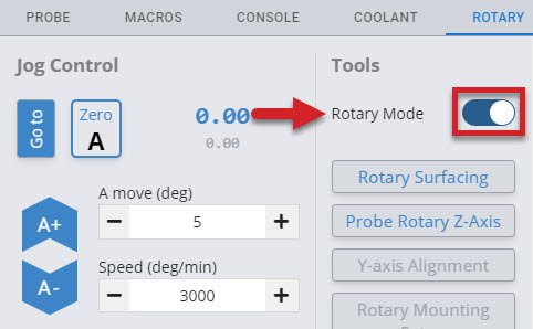
When you enable Rotary Mode, several changes will happen to your tool options:
- The Y-axis Alignment and Rotary Mounting Setup buttons become grey and hidden. This is because your Y-axis will be locked in its current position at this time, so there is no need to align it, and your rotary should already be set up.
- The Stock Turning and Probe Rotary Z-axis buttons become available
Several changes will also happen to your controls:
- The Go to button for Y-axis and Z-axis is hidden
- The Zero Y-axis button is hidden
- It changes the ‘Go to XYO‘ button to be a ‘Go to XAO‘ button
- The Y-axis jogging buttons are hidden
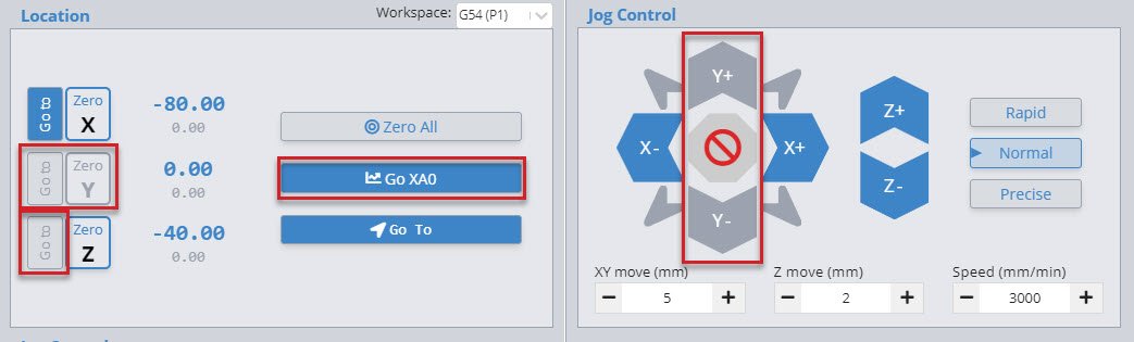
You will also see a reminder that:
- Your Y-axis will be set to Zero
- Your hard limits have automatically been turned off
- Your firmware EEPROM values have been set to new values, better suited to the rotary.
With a final check to ensure that your switch is turned to rotary, click OK to finish enabling Rotary Mode.
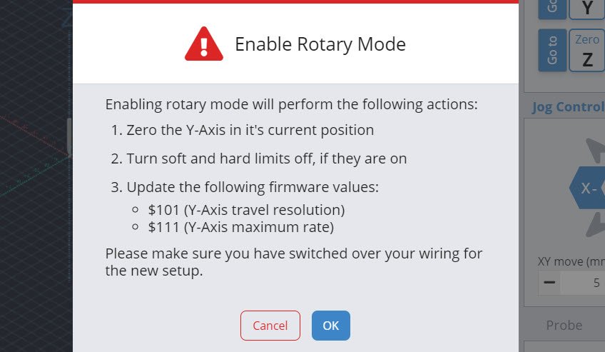
Rotary Probing
In a similar fashion to regular cnc machining where you set a zero position in relation to the stock you are using, we will do the same when rotary carving. Two differences are that we don’t need to enter a tool diameter and each axis will be set separately.
Setting Z-axis
You can set your Z-axis to either the rotating axis center, or the surface of your stock in a similar fashion to regular CNCing. We recommend using the axis center, as that allows you to make use of the Vortex’s built in Z-axis probing functionality.
To do this, jog the cutting bit to be hovering approximately ~15mm just above the chuck. Double check that your probing wires are in place before proceeding!
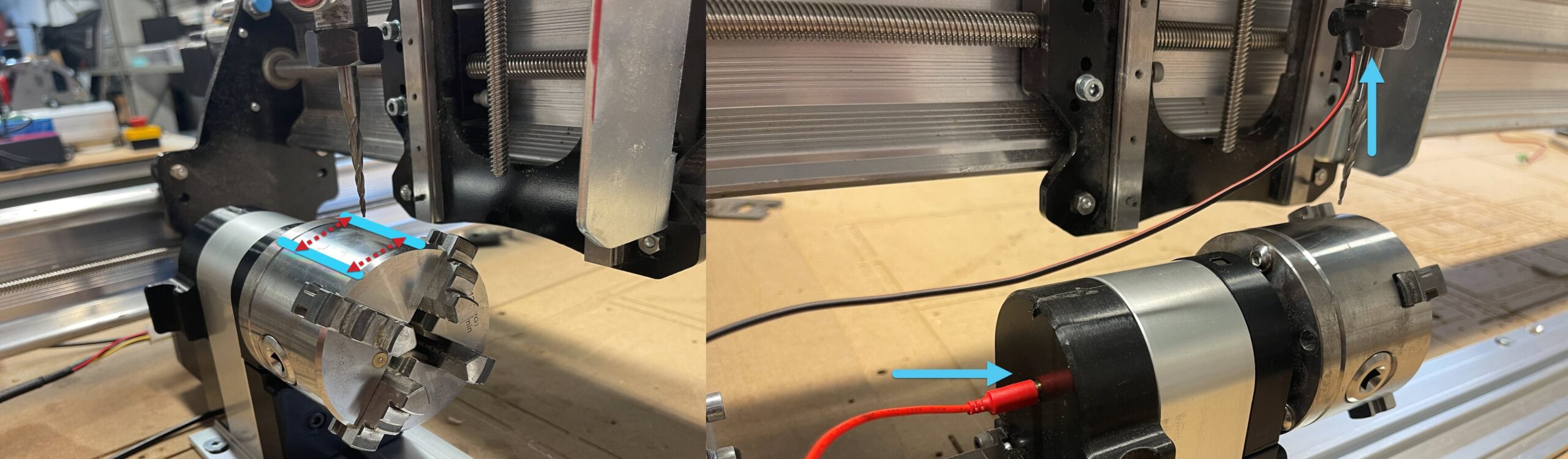
In gSender, select the rotary axis tab, then Click ‘Probe Rotary Z-axis’ and the Z-axis will begin probing automatically, setting the Z-zero point for you. This will need to be done for each tool change in addition to the beginning of each job.
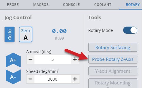
Setting X & A-axis
Setting both the X-axis and the A-axis are done manually.
- To set your X-axis, jog to wherever you’d like the job to start then click ‘Zero X’ to set your X-zero point. Make sure this is far enough from the chuck to ensure there won’t be any collisions with your cutting bit, workholding or screws.
- To set your A-axis, simply click ‘Zero A’ at the beginning of each job, under the Rotary Jog Controls. Note that if this isn’t done, the rotary will spin back to zero before the job starts.
Rotary Surfacing tool
he Rotary Surfacing button will allow you to turn square stock down to a cylinder. We recommend using a ¼ inch upcut end mill for turning stock, as it’s the most efficient.
Now you will see the Rotary Surfacing Tool. Here you will enter details about your stock length, start and final dimensions. You will also see spots for Bit Diameter, Step over, Spindle RPM, and Feed rate.
Rotary surfacing is similar to the regular XYZ surfacing tool. Let’s explore this a bit further.
- Your start diameter is the largest diameter on your stock. Usually this means the diagonal distance from opposite corners if you’re starting with square or rectangular stock.

- Your final diameter is determined by the short side of your stock.
- With a starting height of 90mm and a finished height of 63.5mm, we are removing 26.5mm of material. However, since we have the Z-axis set at the center of the material, we will need to divide that 26.5mm in half. We are basically taking 13.25mm off of the top and the bottom. If you want a single pass, your step down would be 13.25mm. Dividing that by two and setting the step down to 6.625mm, means that we will be doing two passes. This will produce a piece of round stock with the maximum diameter possible.
(Start Height – Finishing Height) / 2 = Total Step down for ONE pass
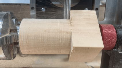
Rotary Settings
When you click on the setting button and then select the Rotary tab, you will see the firmware configurations. Here you can enter your own settings, reset the default settings and turn Hard Limits on/off.
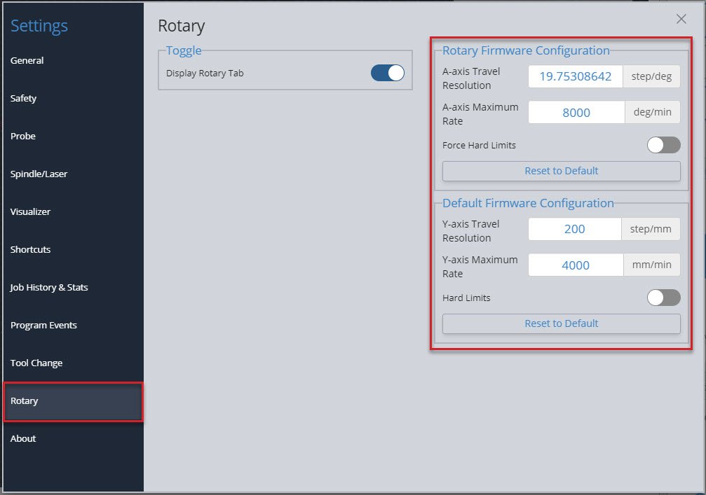
About Page
You can find the release notes for the latest version of gSender in the “About” section of the settings.
More
Check out this livestream if you’d like to see a super deep dive on gSender and all of its features as of 0.6.9. Chris spends a lot of time answering questions live about gSender and how to set up for a project:
Community Macros
Disclaimer! These Macros are submitted by our community. They aren’t vetted by us and might cause damage to your machine so use them at your own risk! Please review the code and test it before assuming it will work with your machine setup.
Formatting
If you’d like to add your own macros to this page, edit the page on GitHub and use the template below for each macro.
Problems or Bugs?
Having troubles with gSender (classic) or have suggestions to improve it? Here are the steps you can follow:
- Questions or suggestions are always welcome!
- If you’re having a problem, first help us out by ensuring that it’s not an issue on your end with your computer or CNC. If you can try with another computer or g-code sender and still see the same problem then certainly let us know.
- If you’re sure about the issue, and have already checked our docs, YouTube playlist, and Common Problems & Fixes below, give us a hand by sending us as much information as possible so we can help diagnose your problem more easily.
Information to Send
In order of importance, please collect together information of:
- Your computer Operating system and gSender version
- Please connect to your controller, try to recreate the issue, and as soon as it happens again create a ‘Diagnostic PDF‘ to send to us. If you can generate this shortly after the issue that’s ok too, but it won’t allow us to help you if you’re not connected to your machine or you generate it too long after you had the issue happen. Find this by clicking on the ‘Calibrate’ tool in gSender, then clicking the ‘Download Now!’ button in the bottom, right corner and saving it on your computer.
- gSender Settings, get these by going to Settings and locating the “Export Settings” button, then saving the file on your computer.
- Machine Firmware, get these by going to the ‘Firmware’ tool and clicking the button for “Export Settings”, then saving the file on your computer.
- Your g-code file if you’re seeing the problem only with a specific file
- Any other pictures or videos of the problem can also help us to help you faster
Please attach the files and information in your post / email to us.

Questions or Suggestions
Send us the information, questions, or suggestions either on:
- The gSender Forum
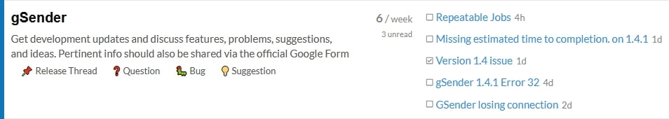
- Github page (feel free to also submit PRs)
- You can join the discussion on secondary communities like our Facebook gSender Group, and Facebook CNC Group, but we can’t provide as much support or hear feedback in these groups.
Common Problems & Fixes
We’ll continue keeping our ears out for common stumbling points while using gSender and ensure we address them here for quick reference. If these tips don’t help you, remember you can contact our support if you have a CNC from Sienci Labs or contact your own manufacturer’s support for instructions on fixing your machine.
Issues downloading or opening gSender
- The main cause of this is usually a “virus protection” or Firewall software on your computer, or your computer system itself, thinking that gSender is ‘unsafe’ even though it’s a proven software. In cases like these, first find the source of the blocking and then either make an exception for gSender or disable the blocking temporarily during download and installation.
- An example of this is if you see “Windows cannot access the specified device, path, or file. You may not have the appropriate permissions to access the item.”
- For Windows-based computers you can read more on it here: https://support.microsoft.com/en-us/topic/-windows-cannot-access-the-specified-device-path-or-file-error-when-you-try-to-install-update-or-start-a-program-or-file-46361133-47ed-6967-c13e-e75d3cc29657
- If gSender used to open fine but after an update it suddenly doesn’t, check here since the update might’ve gotten corrupted: https://resources.sienci.com/view/gs-installation/#gsender-updates (scroll past the first picture)
- If when you open gSender it gives you an error along the lines of “Entry Point Not Found“, this means that you’re trying to use a version of gSender past 1.2.2 with a 32-bit system. If you want to resolve this you’ll either need to continue using a version of gSender 1.2.2 or earlier, or change to using a 64-bit system.
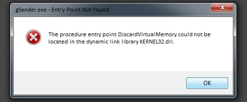
Screen goes Blank
If you find that gSender goes blank after you open it or while using it, there are a couple things you can try.
- Try to close and reopen gSender. If it makes a black screen again, then close and open gSender again ➜ Go to the settings ➜ Export your current settings if you care about them and want to later reload them ➜ then “Restore Default settings”. After doing this it’s more likely you won’t have an issue again.
- If you’re using gSender Edge, you’ll see a toolbar at the top of the app where you can click: View ➜ Toggle Developer Tools ➜ then look at the ‘Console’ where if you find any errors you can share these with us. Also if you click: View ➜ Reload, you’ll be able to refresh gSender to not show the blank screen anymore.
- Otherwise if you’re using the main version of gSender, you can try updating to the latest version.
- Check your antivirus software or Windows Defender and add gSender as an exception.
- Check to ensure you have read/write permissions for the preferences file
- Let’s locate the file! It’s called .sender_rc and can usually be found on your hard drive at: C:/users/{your username}/.sender_rc
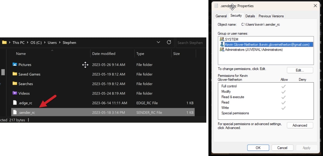
- Right-click on the file and choose properties. Under the security tab, check the name of your profile and confirm you have full control of the file.
- If not, select edit, choose your computer name, and grant permissions.
- Let’s locate the file! It’s called .sender_rc and can usually be found on your hard drive at: C:/users/{your username}/.sender_rc
- If you’re still getting a blank screen, locate your log file and send it in to us. It’s located at: C:/Users/{your user name}/AppData/Roaming/gSender/Logs/main.log
Use gSender without a CNC
It’s not easy for us to simulate how a real CNC will behave if you’re not connected to one, but luckily there are some workarounds:
- Buy a cheap “Arduino Uno”: this board is the ‘brain’ that runs many Hobby CNCs and can be easily found online or in some stores for around $10. Once picked up you can connect it to your computer over USB, flash Firmware onto it to make it behave like a CNC, then you’ll be able to connect to it in gSender. There are limitations such as not being able to home or probe (any sensor inputs) unless you manually short them together yourself; and this is because obviously you’re not connected to a real CNC.
- Use a file simulator: this won’t let you pretend to run your CNC in gSender, but can simulate how a cut might turn out. You can read more about these options here.
Connects but status says Disconnected
If your machine connects on a COM port successfully but the machine status says “Disconnected” then this is not an issue with gSender. A ‘Disconnected’ status means that gSender isn’t able to recognize your CNC even though it can see it.
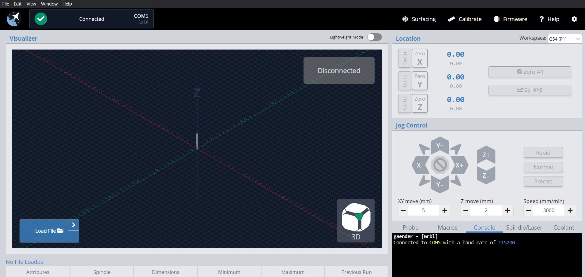
- Check that you have the right settings for your board, for instance click Settings ➜ Baud rate where most boards use 115200. Also your machine might not be supported yet by gSender if it isn’t using grbl or grblHAL or your manufacturer edited the core firmware too much.
- Your board may have a faulty connection. Try unplugging it then plugging back in, use a different USB cable, a different USB port on your computer, or plug the cable directly in if you were using a USB hub.
- Your board might have other loose connections. Power off your machine, then use a non-conductive tool like a plastic utensil to push down on all 4 corners of your control board shield or Arduino. For the LongBoard you don’t need to open it, just flip it upside down and you’ll be able to access the Arduino through the slats on the bottom. Doing this will ensure that everything is fully plugged in since sometimes if the Arduino is slightly off the control board it can mess with its communication.
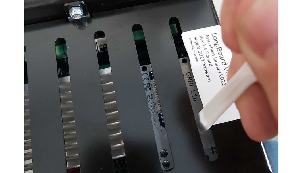
- Your board might have corrupted firmware. Re-flash your board if it’s a LongBoard, SLB, or by following your manufacturers instructions.
- At the least when you plug the board to your computer over USB you should hear a ‘connection’ sound from your computer. You should also see a new device appear under the Devices and Printers on your computer. If none of these are happening, then that means your computer isn’t recognizing the board so you might want to look at drivers or getting further technical support.
My CNC Profile is not listed
Much of the information that gSender needs about your CNC actually comes from its built-in EEPROM values, so the CNC profiles don’t have any impact. This means that as long as your CNC is grbl-based, gSender should be able to control it just fine, even if it’s not listed in the presets. Selecting the “Generic” preset will work just fine.
If some aspects of your machine don’t seem right, it’ll either be because your machine’s manufacturer didn’t flash your CNC with the appropriate EEPROM settings out of the box or they have some type of documentation which explains the values you need to change manually.
Port not Found (3018 CNC)
The 3018 and similar variations have been tested to work with gSender. Sainsmart points out in their documentation that sometimes an additional driver is needed for your computer to recognize the CNC via the USB port. They make this driver available for download here.
In case this link stops working, the associated documentation can be referenced here.
For most of their machines they recommend using a 115200 baud rate, so double-check you’re using that value as well.
Port not Found
As long as your board is running normal grbl or grblHAL and you’ve selected the correct Baud rate in the settings then connection should be possible. Double-check that you’re not connected to your machine elsewhere like with:
- Other senders like Easel, CNCjs, UGS, Lightburn (some programs might auto-connect so you might have to close them entirely)
- Pendants or offline controllers since typically a sender and controller can’t be used at the same time
- Other programs like Arduino IDE or STMCubeProgrammer
We’re still working on making gSender work best across all devices and one aspect of this is port detection for a variety of CNCs. If your CNC still isn’t showing up on the port detector, we’d really like to hear from you.
One key bit of information that we need on our end is a picture or screenshot of your device information. You can get to this screen by:
- Make sure your CNC is plugged into your current computer via USB
- Open “Device Manager” in your Windows start menu
- Expand the “Ports (COM & LPT)” heading
- Find the listing related to your CNC. This will be the one that disappears and reappears if you unplug your CNC and plug it back in. It’ll also be the port you normally connect to on other g-code senders.
- Right click that device and open “Properties”
- Open the “Details” tab at the top
- In the “Property” dropdown, select the “Hardware Ids” option
- Send us a picture of the final view. An example of what that might look like would be:
We appreciate your feedback, and with your help we’ll make sure the next version of gSender recognizes your machine.
File is Tiny in Visualizer
You’re probably using the wrong post processor, go back and check what your CNC manufacturer recommends. By default it’s best to use “grbl_mm” even if you like to use inches since most CNCs work in mm.
Jogging not working, I get an Error
If you’re seeing a message in the ‘Console’ tab saying “error: Bad number format”, this is because you’re running an older grbl machine (pre Grbl 1.1f). Contact your CNC manufacturer or look through their resources to see how you can upgrade your grbl firmware so that your machine can be fully supported by gSender. If you have a Sienci Labs machine, this is as easy as using the ‘Flash grbl’ option in the ‘Firmware’ tool in gSender.
Alternatively, you could be getting an error for ‘soft limits’. If this is the case then either your machine limits have been set incorrectly or you didn’t home your CNC when you first connected to it. Try homing your machine and trying again, and keep an eye out for if you’re only having this issue in certain parts of your cutting area.
Gamepad Error or Inconsistent Jogging
If you can’t access your gamepad shortcuts or there’s a problem with the profile, the easiest way to fix it is to delete the profile and remake it. This can suck depending on how much you customized it, and we’ll keep working to make this process work better into the future.
If you can connect and jog with your gamepad but the jogging is sometimes unpredictable, then the problem might actually be the gamepad itself. Go to Settings ➜ Shortcuts ➜ Gamepad ➜ Gamepad Profile ➜ and click the ‘Help’ button at the top of the window. This will take you to a 3rd party Gamepad Tester website (that you can also visit at https://hardwaretester.com/gamepad) where you can try pressing buttons and moving joysticks to see if they’re all behaving properly. If anything seems out of place then you might want to try using a different gamepad to control your CNC.
Changes between “Running” and “Idle” during a Job
This is Normal. Sometimes there can be pauses or long changes in direction in the g-code that can make the machine state change in this way.
Workspace changes during/after a job
If your g-code includes any workspace commands from G54 to G59, G59.1 to G59.3, or has an M2 or M30 command at the end of the program this will alter your selected workspace either to the one specified or revert it to G54. These commands affect how grbl stores the active workspace and so also affect the workspace stored by gSender. If you’re experiencing this issue then you’ll want to check your CAM post processor and ensure that it stops inserting these commands when you export your g-code jobs.
Alternatively, gSender’s ‘Start/Stop G-code’ can also be equipped to sidestep problems with changing workspaces by saving the active workspace at the start of the program and then re-loading it at the end. This can be done with the commands %global.state.workspace=modal.wcs and [global.state.workspace] as shown in the picture below. Remember to ‘Update Event’ on both entries:
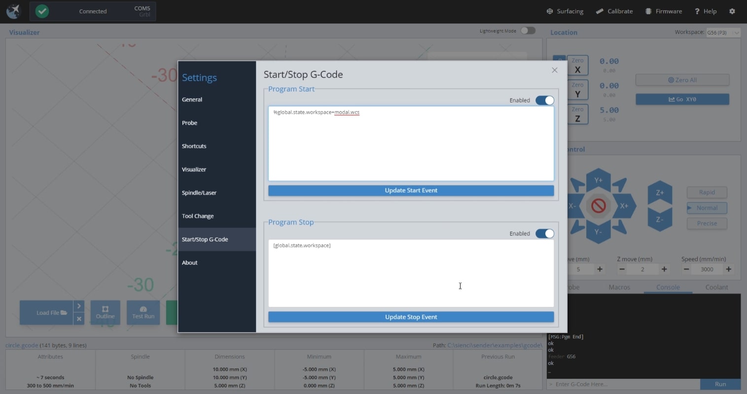
Changed $1 and Motors still Hold
This is a quirk of grbl boards where after changing this value you need to make a motor movement (a jog movement for example) before the new value will take effect.