This page serves as a reference in the event that something goes wrong with your rotary axis either during assembly, setup, or use. If you can’t find what you’re looking for on this page, or don’t find any of the solutions useful for your issue, please feel free to get in touch with us.
For any issues relating to your LongMill, such as general issues while running jobs, connecting to your machine, or the motion of the X, Y, and Z axes, please reference our CNC Issues & Fixes page instead.
Pulley is Slipping
It’s likely that the belt joining the Vortex motor and chuck pulleys was slightly under-tensioned when assembled, or became loose over time.
Remove the headstock from the mounting track by unscrewing the four screws at the bottom. Next, remove the 3D printed front lower headstock cover from the headstock to expose the four mounting screws at the front. Slightly loosen each of these screws, then apply a reasonable amount of pressure downwards onto the motor. While holding this pressure on the motor, re-tighten these four screws at the front of the headstock. Like shown in the photo below.
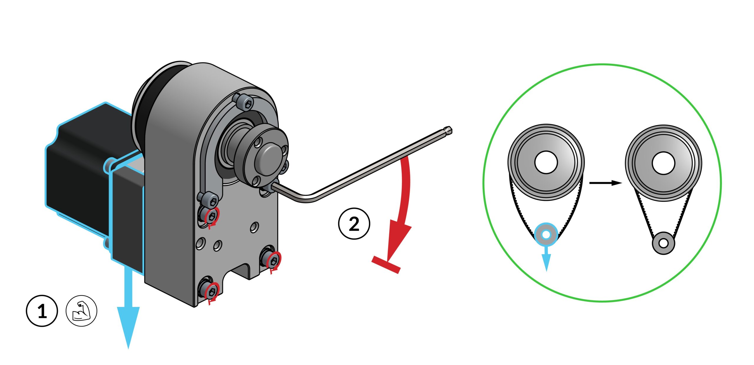
Re-assemble the rest of the components in reverse order. Ensure that the pulley can still rotate freely without any binding or resistance.
If you’ve checked that the belt on your headstock is fully tightened and not allowing for any slop in the chuck’s rotation, you may be cutting too aggressively and causing the motor to skip. This is especially more likely when cutting very large diameter stock (such as 2″+) since cutting forces from the bit will create much more torque applied to the router. You’ll likely want to reference our recommended feeds and speeds chart found here, as well as read about how feeds and speeds are affected by the rotary axis work here.
Backlash in the Headstock
If it seems like the chuck can be spun by hand freely back and forth, it’s likely that one of the set screws within the motor or headstock shaft pulley have come loose.
To check this, remove the two screws holding the rear cover of the headstock in place, then remove the four screws holding the motor onto the back of the headstock. Remove both the cover and motor from the head stock, then slip the belt off of the two pulleys. Check the fitment of the two pulleys onto their respective shafts and try turning each by hand to check for looseness.
If a pulley seems loose, identify the small set screw which sits closest to the flat portion of its respective shaft, then tighten this so that the screw bottoms out onto the shaft and there is no more play in the pulley. Tighten the second screw as well.
Chuck & Stock Wobbly
A wobbling chuck (and stock being held) indicates that the chuck back plate was not installed fully seated. Remove the three screws at the back of the chuck, then check the tightness of the three screws mounting this plate onto the headstock shaft. If you can see any small gaps between these two components, tighten down these three screws to continue pulling the two into alignment.
Tailstock is Not Parallel
If you notice when cutting with the Vortex that certain sections of your carved model have curved lines (when they should be straight), and certain sections seem warped, it’s possible that your moving X-axis is not aligned parallel perfectly to the Vortex’s rotary axis.
This can happen for one of two reasons and can be resolved as follows:
- The Vortex’s mounting track holes in the wasteboard have threaded inserts that are not fully seated, therefore the mounting track is not perfectly square with the machine.
- Run the hole mounting program again, making sure to run both the Y-axis gantries all the way to the front or back of the machine in order to align the X-axis before running this program and ensure your threaded inserts are fully seated and level.
- The X-axis rail is not squared, due to one of the left or right Y-gantries becoming out of sync with the other.
- Running the machine all the way to the rear of the machine (or front) until both Y-axis motors skip will cause the align the X-axis rail to realign itself.
Jogging the A-axis Causes Jogging the Y-axis
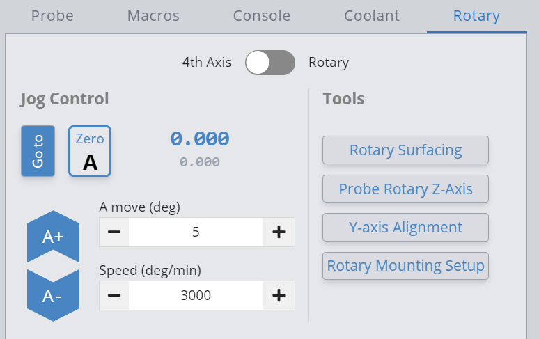
If you are using the Closed Loop Vortex, please restore defaults in your firmware then make sure to stay in 4th axis mode. Do not switch between Rotary and 4th axis.
Rotation is Incorrect
- If you have the Closed Loop Vortex, make sure you are in 4th Axis mode. If you have the Open Loop Vortex, make sure you are in Rotary mode.
- Click console and input or copy/paste the following exactly, $103=79.012345679, then click RUN. Write this number down in case the settings have been changed back to default.
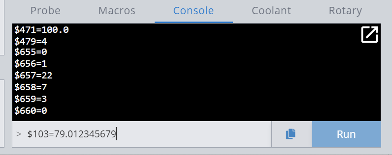
- Disconnect from, then reconnect to the controller.
- Open the firmware tool and confirm the setting has been updated. It should appear as below.
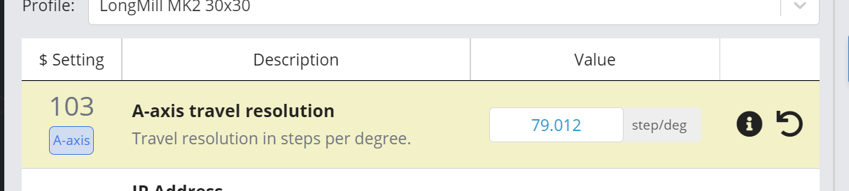
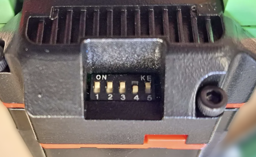
- If that does not work, please ensure that the DIP switch on your Closed Loop Vortex motor is set as shown below: ON-ON-ON-OFF-ON
Surfacing is Cutting Notches in Stock Material
There is a known gSender bug (as of version 1.4.11) that involves the closed loop stepper and Vortex surfacing in inches. For now we recommend reducing stepover to 25x less than usual, as the workaround. Our software team is planning to address the bug with the upcoming gSender releases.
Y-axis Alignment Probe is not Completing
Make sure $101=320 by going to the Firmware Tool on gSender. If not, go to the Console on the bottom of the screen, then type in $101=320 and press enter.
Motor Pulley is not Installed
If you received the Closed Loop Upgrade Kit without the motor pulley pre-assembled, please follow the installation instructions below.
 set screws for installation")
Take out and put the pulley on the motor. Then align the pulley so that the set screws face the flat side of the motor shaft.

Use a 3mm or M4 allen key to space the pulley off the motor face, keeping alignment with the flat.
If you have Loctite Blue, apply it on the threads of the set screws.
Use the provided 2mm allen key to tighten the set screws.

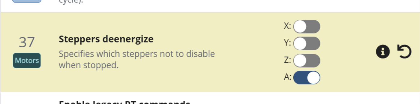
A-axis is slow to respond when jogging
Typically this happens on the closed loop Vortexes. To fix this, go to the Firmware Tool on gSender, scroll down to $37 and toggle the A-axis ON. Power cycle your board by turning it OFF then ON, then reconnect to gSender. You should be able to jog without a large delay.