
Congrats on upgrading to our newest and most powerful CNC controller to date, the SuperLongBoard!
Our main goal in this section is to have you go in with a working CNC, then leave with an SLB-boosted machine without skipping a beat. This guide will be written to try to accommodate switching over from other controllers on the market that you’re swapping out for the SuperLongBoard (SLB, on the right).
Unpacking
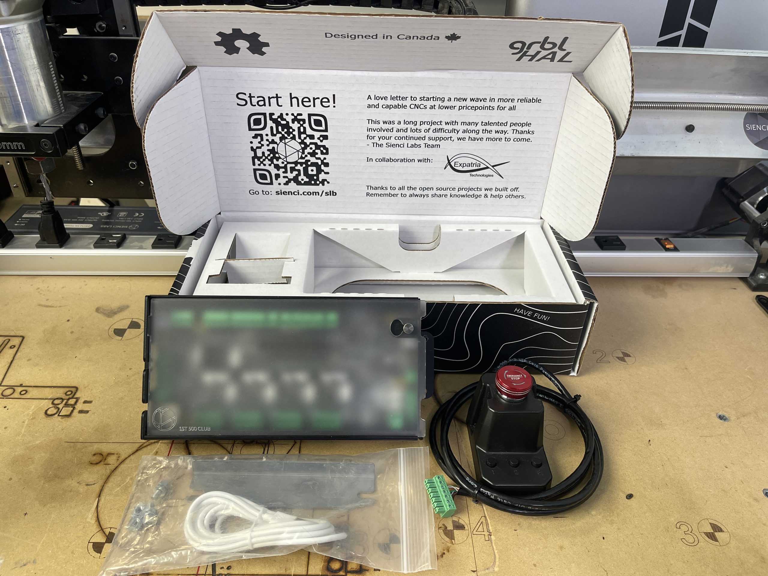
In the box you’ll find:
- Your new SuperLongBoard inside it’s aluminum enclosure
- E-stop with 3 additional ‘Action Buttons’ that are customizable
- E-stop cable, plenty long to increase mounting options
- And a USB-C cable, MK2 mounting hardware, and some spare connectors
- A spare baggy of 5.08mm plugs to connect power and stepper motors to your SLB. If you didn’t email us before purchasing your SLB, you might be missing these so you’ll need to source them yourself (first two plugs on the list).
The only other parts that you’ll need to supply yourself are:
- The minimum 24V 10A power supply needed to run the SLB (you can use the one for your old control board if the specs match, otherwise we also sell them)
- Your CNC machine, already tested to be working using its existing control board
- A computer running gSender with a free USB port
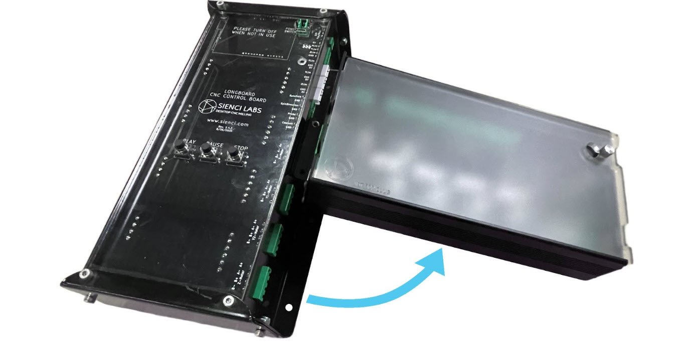
We hope everything arrived well and in one piece! Let’s take the cover off the SuperLongBoard and see what’s under the hood.
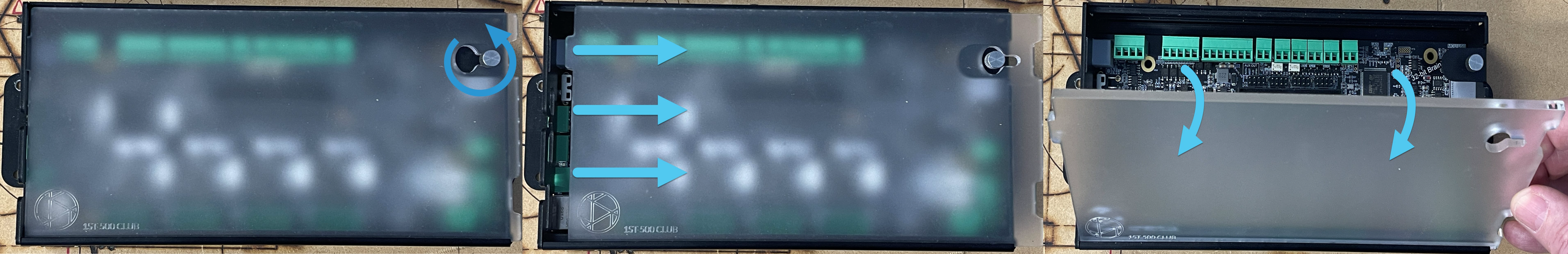
Unscrew the top-right thumbscrew a couple turns (pictured) then slide the cover to the right. Once the hole in the cover lines up, you’ll be able to pull the top of the cover towards you and it will come free.
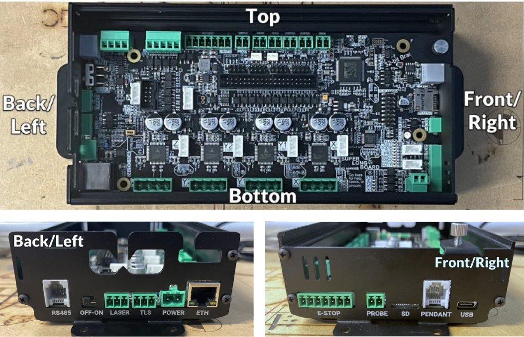
To help communicate where things are on the board, we use the terms shown below:
Preparation
Before diving into rewiring, we’d first suggest you note down any attributes that are unique about your setup. This is so that once you switch over to the SLB you’ll be able to create the same setup with the same settings.
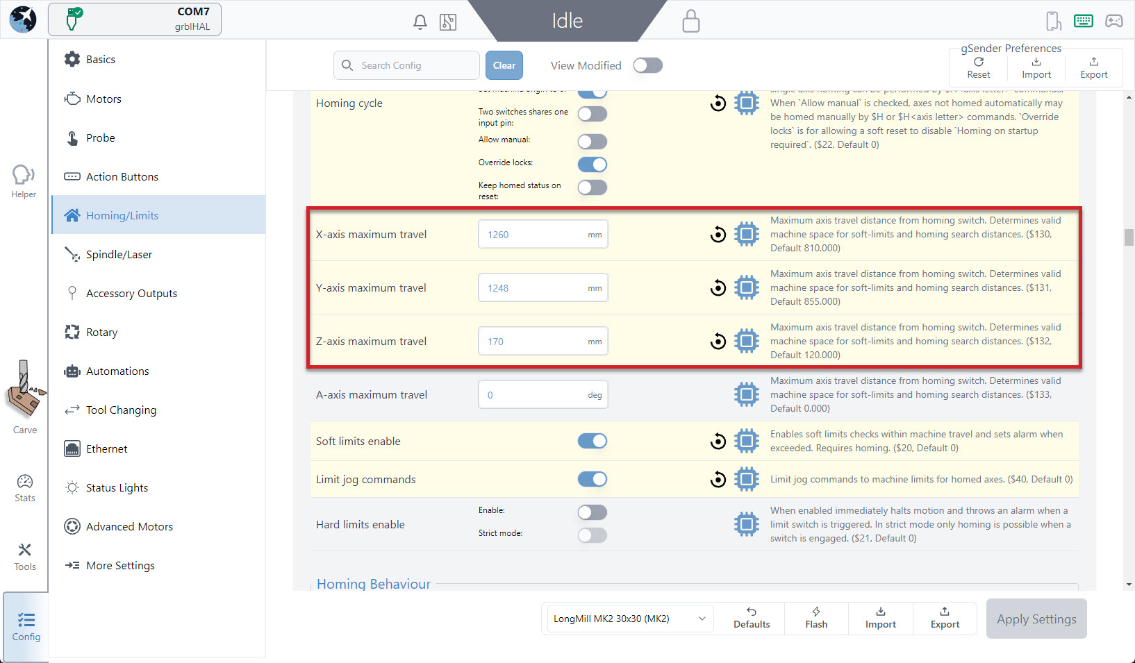
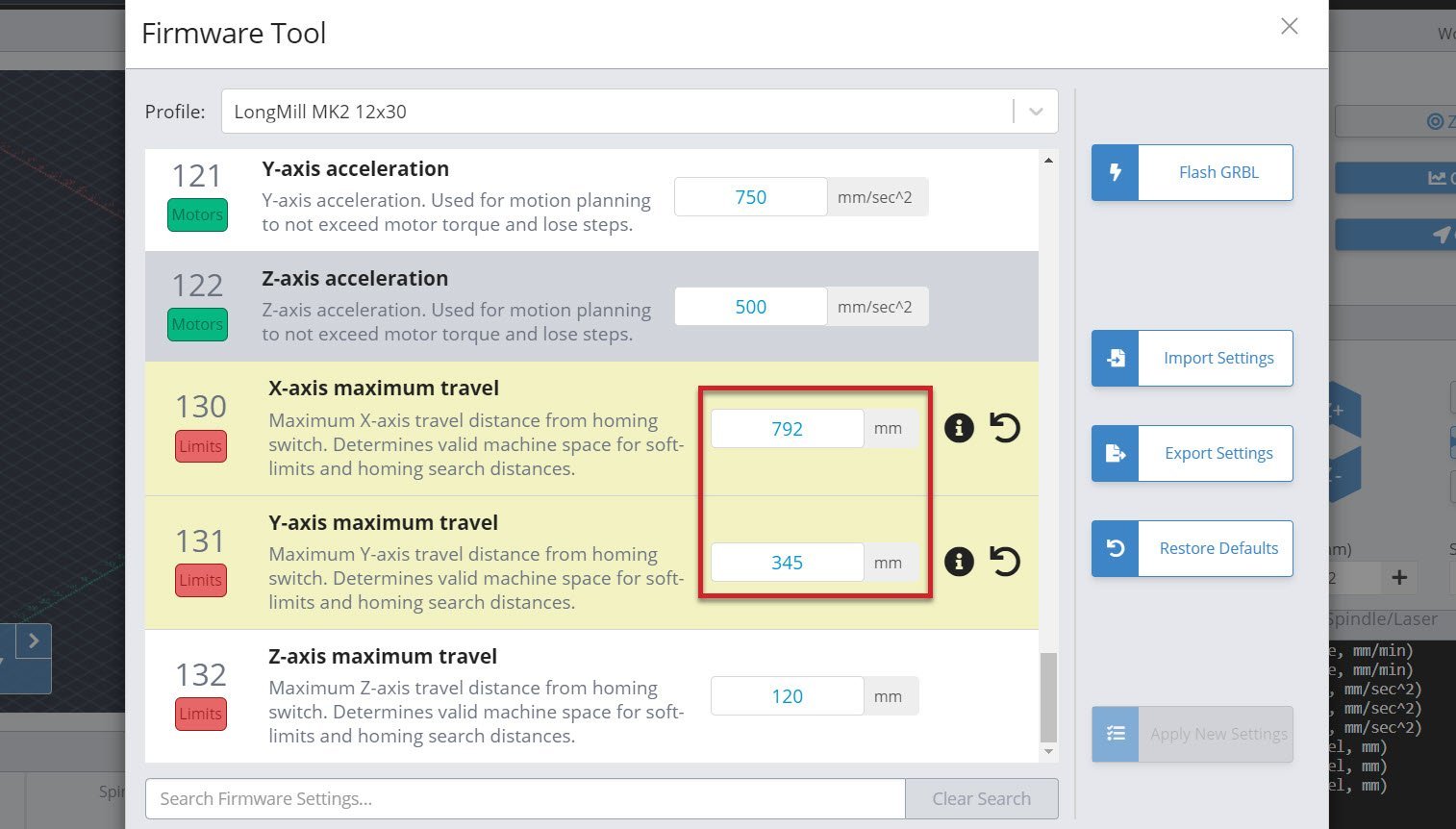
If you use gSender, you can do this by connecting to your CNC and using the Config tab (Current gSender) or Firmware Tool (Classic gSender) to find sections that you recall setting up or changing; things like max travel, speed, etc. It won’t be disastrous if you forget to record any of these settings, since your old controller should still work so you can always go back and double-check it’s settings.
Wiring xPRO V5
Let’s start moving plugs over to the SLB!
This is a community-contributed document so information might not be the most up-to-date so please submit feedback at the bottom of the page if you find anything missing. Another great resource to reference is the one made by SparksTech below:
- Power off your xPRO controller, then begin unplugging all the various wires one-at-a-time
-
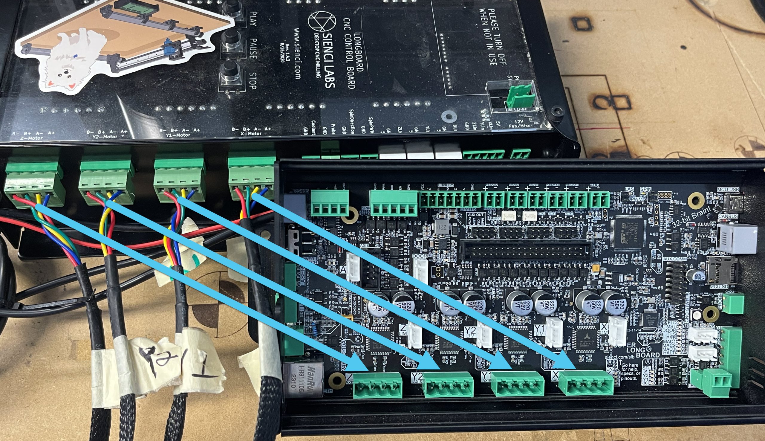
Start with the X, Y1, Y2, and Z stepper motor connectors. Use a small flat head screwdriver to unscrew the wires from the xPRO connectors and transfer them to the SLB connectors, making sure to keep them in the same order.
-
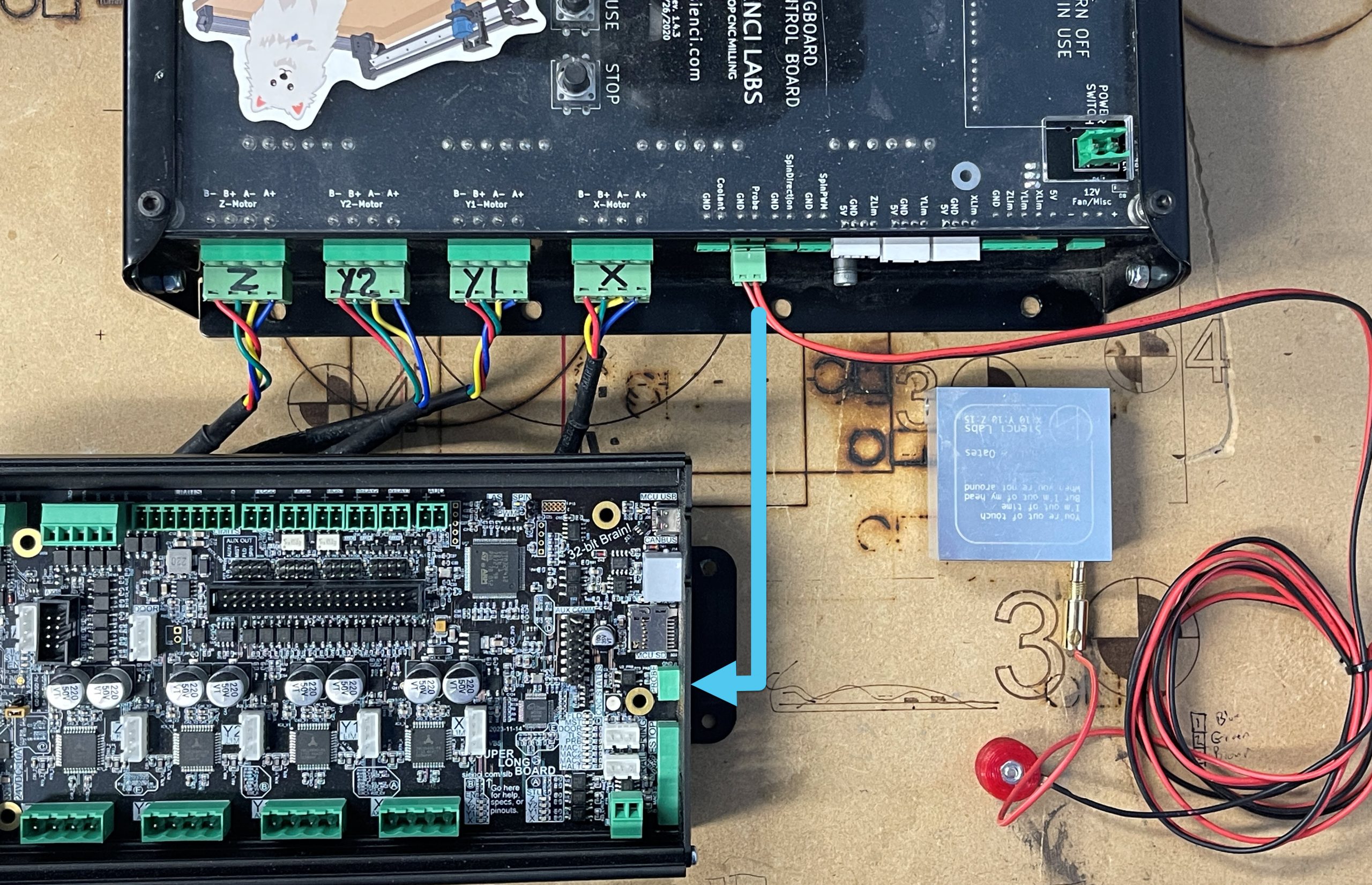
Unplug your touch plate/probe and plug it into the SLB, on the Front Side.
-
Grab the new E-stop and plug the green end into the Front Side of the SLB, then the other end into the backside of the E-stop.
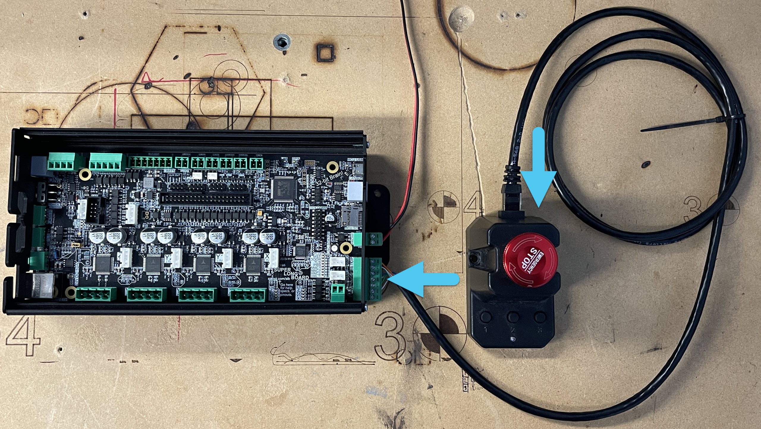
-
Now grab the USB-C cable that came with your SLB and plug it into the Front Side of the board. Plug the other end into your computer.
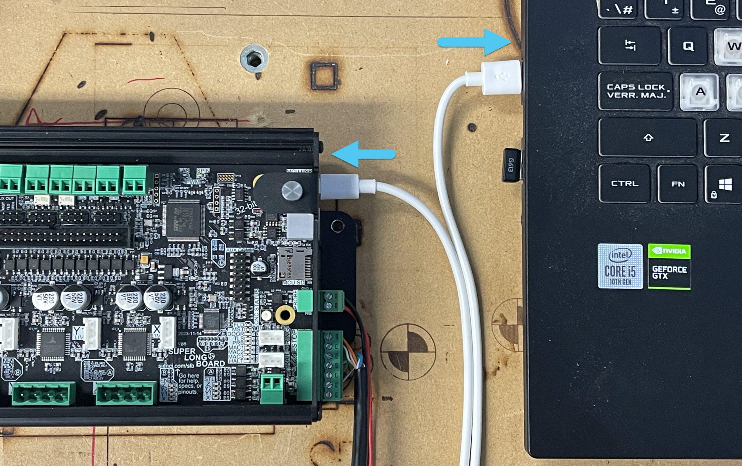
-
You’ll need to reverse the polarity of the xPRO power connector so that red is on the left side and black is on the right. Once it’s rewired, you’ll be able to plug the power connector into the Back Side of the SLB.
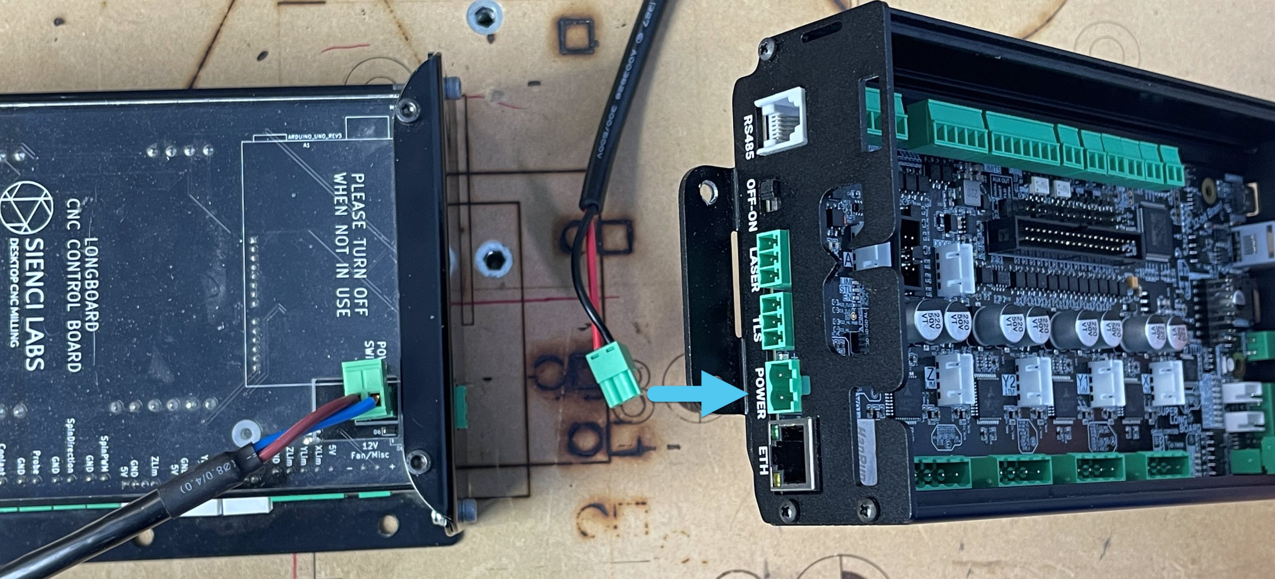
-
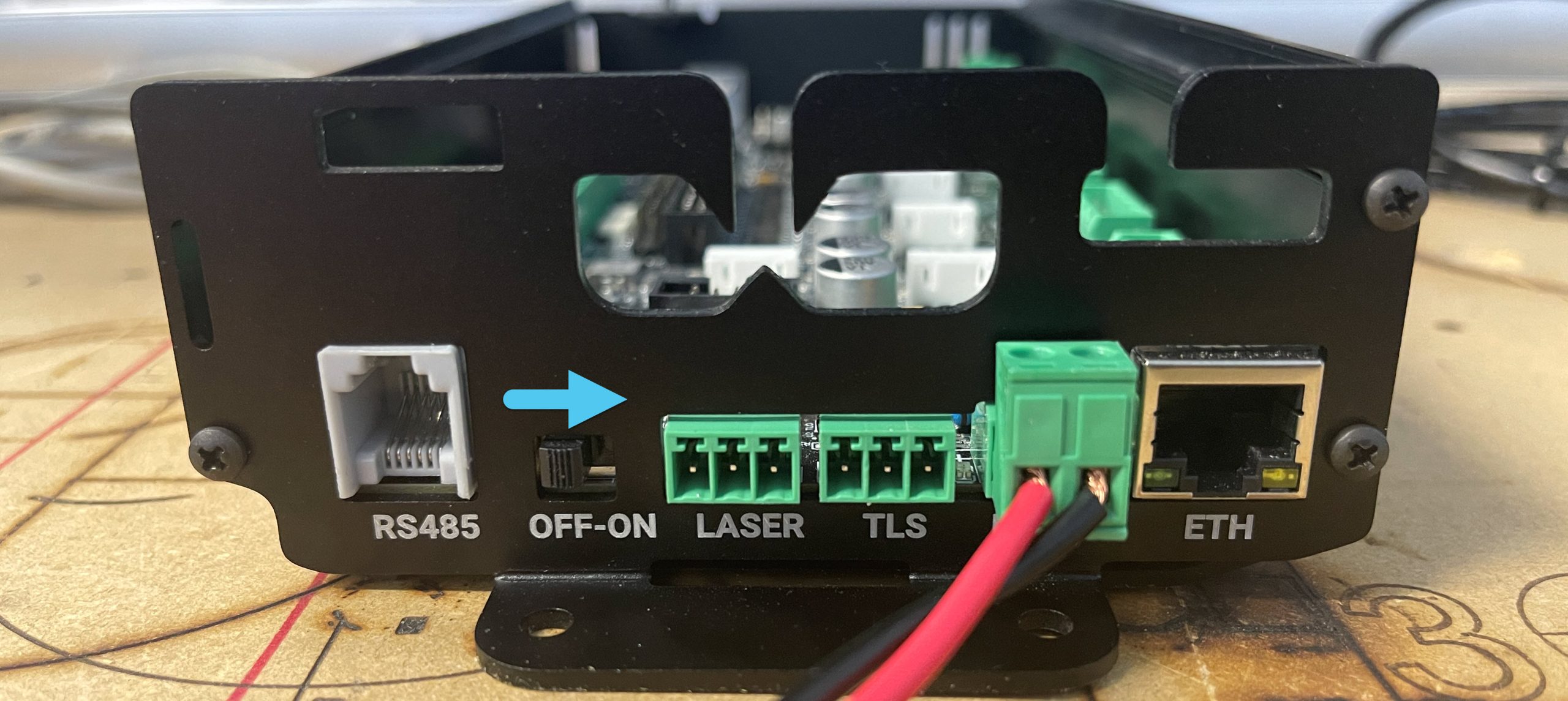
Lastly, when looking at the Back Side of the SLB, you will see a power switch. Slide it to the ‘ON’ position to power on the SLB. It’s Alive!!
Congratulations! You’ve wired up your new SLB with all its typical accessories! If you still have other, slightly less common accessories to wire in, then keep reading the next section; otherwise you can move over to gSender to connect and do some quick tests.
Optional Wiring
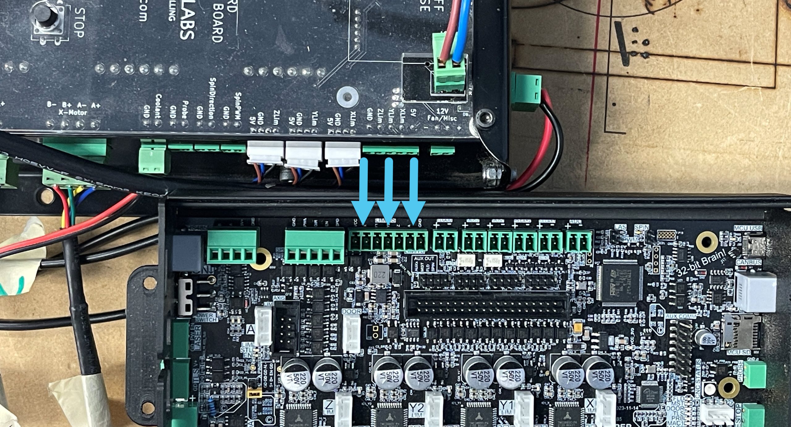
If you have Limit Switches, you’ll need to wire them in using the Auxiliary terminal connector input (shown below). One trick about this is that the connector has a shared ground, so you’ll want to either joint-crimp all your wires together, use a WAGO connector, or use a ground bus.
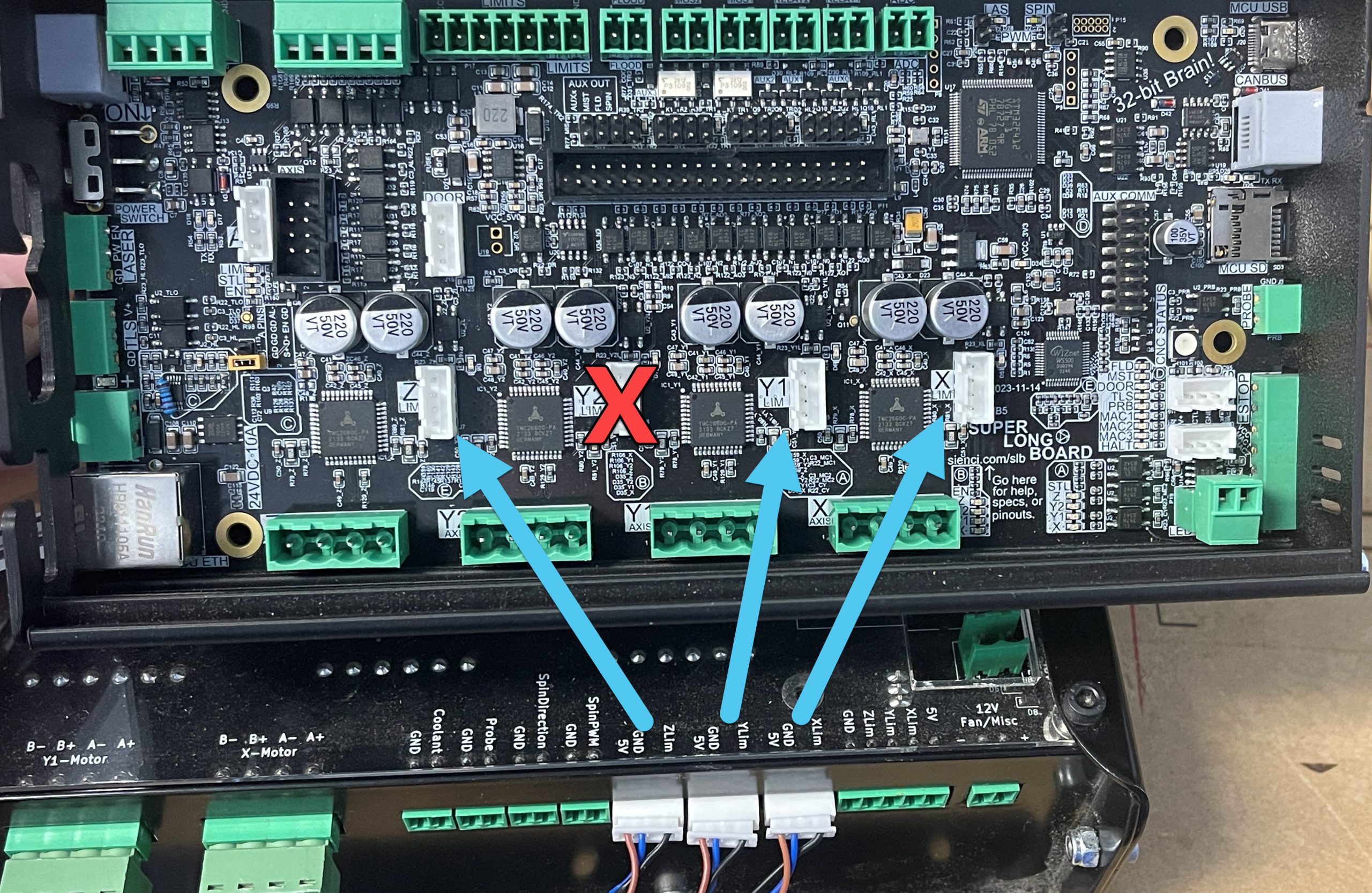
Note: The Y2 connection isn’t used at this time
If you have the resources, you can also crimp on 4-pin JST connectors and plug them straight into the corresponding plugs on the board. Sienci inductive sensors come with these by default, as do other common sensors.
Once you’re feeling comfortable with your setup, you can go back to the main “Upgrading to SLB” writeup to see how to set up gSender and run quick functionality tests.
For wiring other accessories like a Laser Diode, IOT Relay, Spindle over RS485, and more, then we’d suggest reading our full Technical Manual page here.
Some of this is also addressed in the second-half of SparksTech’s video where he was able to get Spindle RS485 for the H100 VFD set up, as well as he provides a 3D printable adapter for the E-stop to mount it to his Ultimate Bee CNC. There’s also a topic on our forum discussing the switch-over.
Troubleshooting
If you are still running into any issues with your new SLB, please see the Troubleshooting Section on our more Detailed page. You can also always contact us directly at support@sienci.com.