Touch Plate Setup
gSender has support for three types of touch plates:
- The Standard Block design
- Z Probe, also sometimes referred to as a ‘puck’
- And our specialized AutoZero touch plate
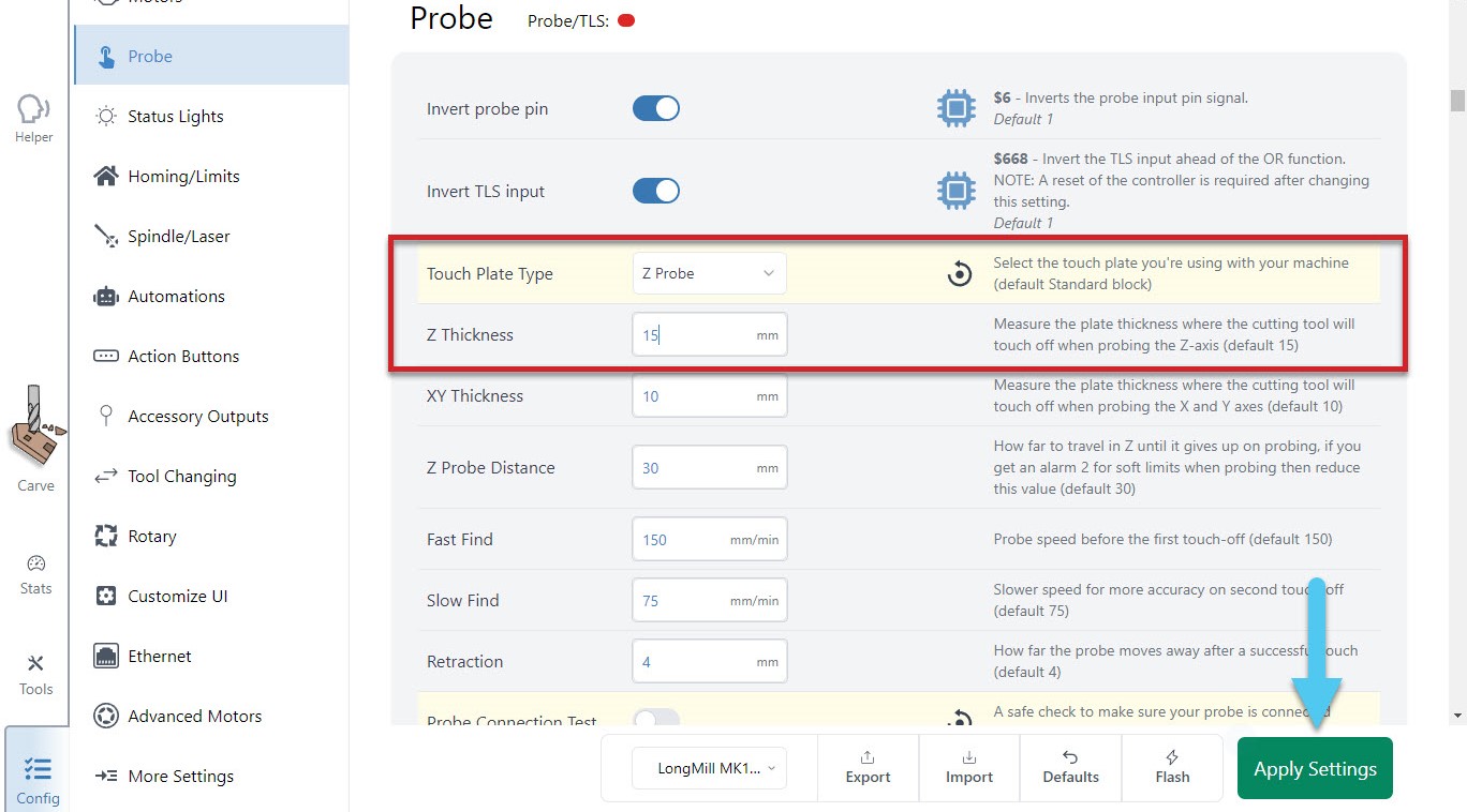
If you’re trying to set up a custom Standard Block plate, use some calipers to make the measurements shown below. Once these are noted down, enter these into gSender’s ‘Probe’ settings in similarly named entries, apply the changes, and now you should find that gSender’s probing routine has been altered to fit the shape of your touch plate.
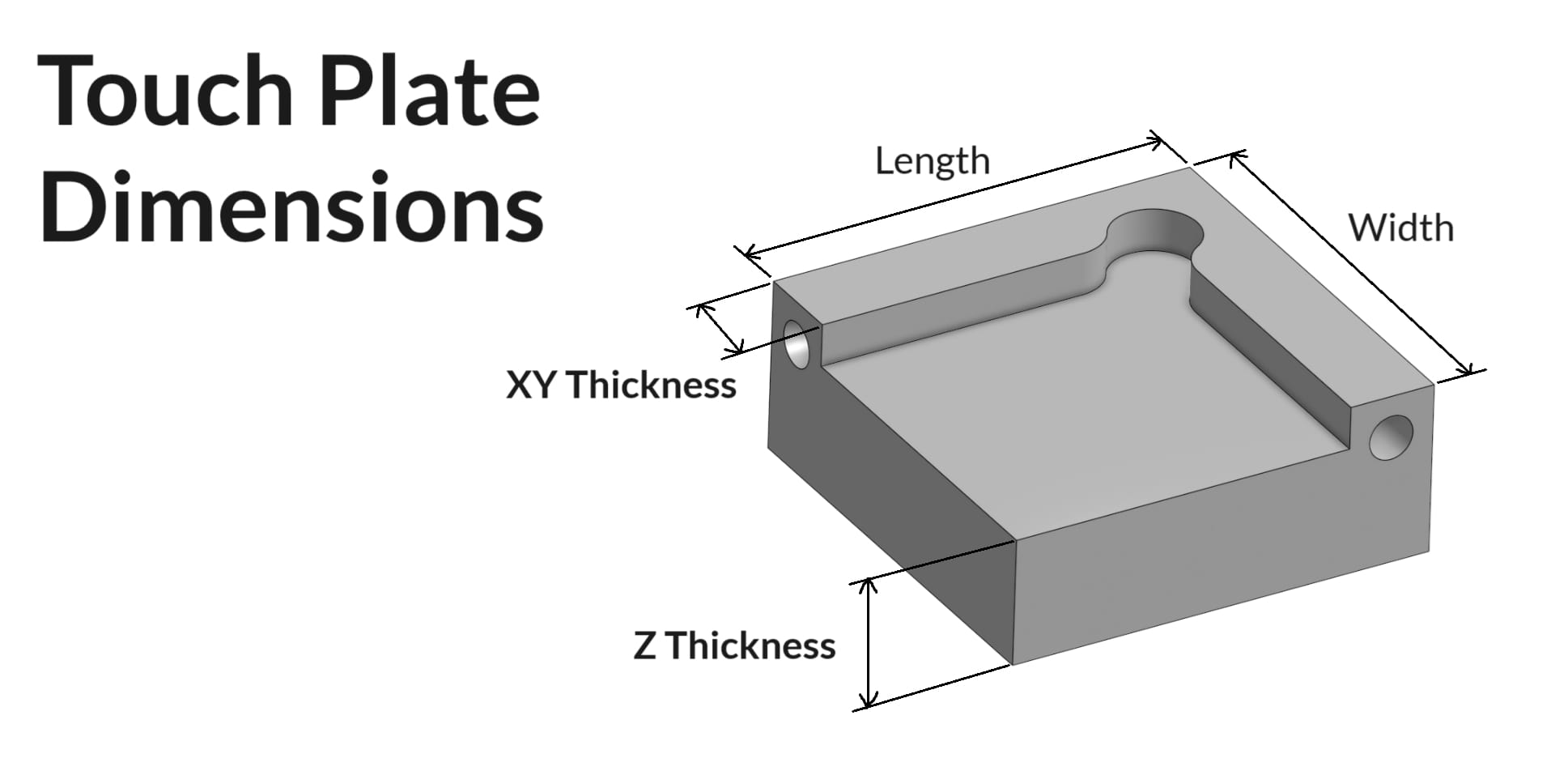
For a custom Z Probe, setting up is simple since you just need the thickness of the ‘puck’. Enter that value into gSender’s ‘Probe’ settings under ‘Z Thickness’, apply the changes, and you should be good to go!
The AutoZero touch plate doesn’t require any setup at all, other than selecting it, and applying the changes!
Spindle & Laser Support
Similar to the manual coolant control, this area is for manual control of a spindle or laser outside of g-code sending. If you have a spindle or laser, you can activate these controls by going to the Config tab ➜ Spindle/Laser section. Here you can enable these functions by flipping the ‘Spindle/laser controls’ toggle. Don’t forget to apply your new settings!
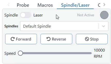
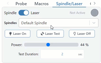
Back at the main Carve screen, you’ll see the ‘Spindle/Laser’ tab at the bottom right. Here you can click to toggle between ‘Spindle Mode’ and ‘Laser Mode’, changing your grbl settings for you and displaying buttons specific to each device. For each mode there is also a warning that will appear in the right, top bar of gSender to inform you if the spindle or laser are active. This will happen both during manual control but also during job sending.
In ‘Spindle Mode‘ you can select your current spindle, adjust the spindle speed with a slider, spin it up in either direction, and stop it again with the ‘Stop’ button. These are all based on g-code commands that can also be entered into the console manually if desired. The speed slider is set from your grbl firmware settings, so max and min speed can be altered in the Config ➜ Spindle/Laser.
‘Laser Mode‘ is very similar, allowing for On/Off control, a slider for setting the laser power during manual control, and a ‘Laser Test’ button. The laser testing function is handy when troubleshooting your laser setup or for other sorts of locating and alignment because it only enables the laser for a short time before turning it back off again. Though this is much safer than regular on/off control, we still highly advise that you have you have a hand on a kill switch or E-stop during testing or control of either Laser or Spindle modes so that in case something goes wrong with your computer or the program they can still be safely deactivated.
Laser Diode Support
Some accessories can be really handy to add to a CNC router like a laser diode, drag knife, or pen plotter. These would all perform better on a faster, dedicated machine, but for occasional use why not use the existing motion system of the router to do other things for you? A laser diode in particular can be great because you can clamp the material to carve and then laser engrave afterwards and know that everything is still aligned.
Since many CNCs are coming with diode accessories, gSender has some unique features to also support lasers. Once ‘Laser Mode’ is turned on, gSender will:
- Automatically apply an offset from the router/spindle to the laser so all your g-code files stay aligned (configured in the Spindle/Laser settings, or with Firmware settings $741 and 742 on the SLB).
- Turn on the laser at low power when running a job outline (enabled in the Spindle/Laser settings). This will help you to better see where your project is going to be located on the material.
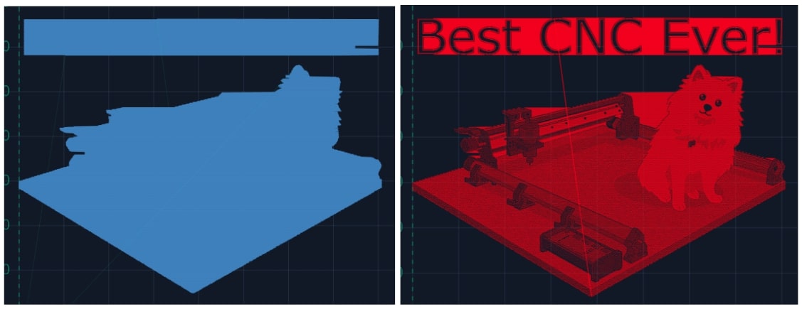
- Switch to a specialized visualization designed to show raster engraving images better than typical g-code visualizers. Seeing the laser intensity in the movements is very useful to get a better idea of what your projects are going to look like when they’re run. This will only apply to files loaded after ‘Laser mode’ is enabled, where you’ll see the colour change from the default blue to red.
Coolant Control / IOT Relay
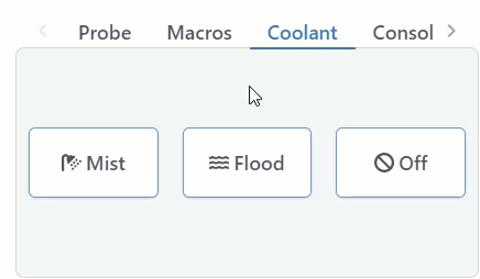
If you have a coolant control pin on your CNC machine, gSender has a tab for manually controlling it. Under the ‘Coolant’ tab on the main Carve screen, you can find the ‘Mist’ and ‘Flood’ buttons to activate the different modes of coolant use, as well as an indicator for whether the coolant function is active or inactive. This indicator also functions during job sending. You can turn off both coolant pins by pressing the ‘Off’ button.
Many hobby CNCers don’t have a need for coolant and so prefer to use these outputs for controlling other periphery. The most common is an IOT relay that can be used to automatically control a vacuum for dust collection, the CNC’s router, LED lighting, and more. See an example of how to set that up here: https://resources.sienci.com/view/lm-iot-relay/
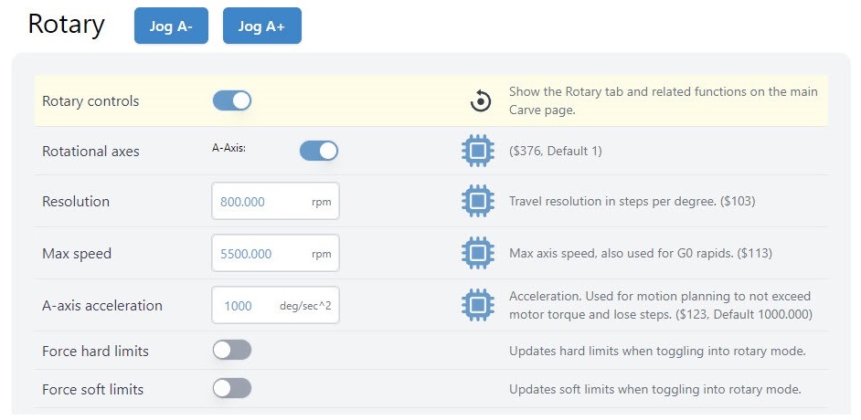
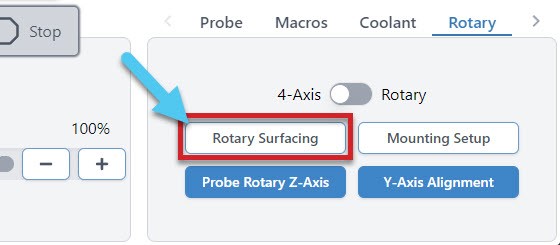
Rotary / 4th-axis
gSender has a unique ability to control a rotary axis on normal, 3-axis grbl and grblHAL machines which we call “rotary mode”, as well as typical 4-axis rotary setups on grblHAL machines. The difference between these two is just a matter of how you set it up and whether your machine has enough unique drivers to control either 3 or 4 unique axes.
In either case, the setup starts by going to Config ➜ Rotary and enabling the rotary controls. Don’t forget to hit the ‘Apply Settings’ button!
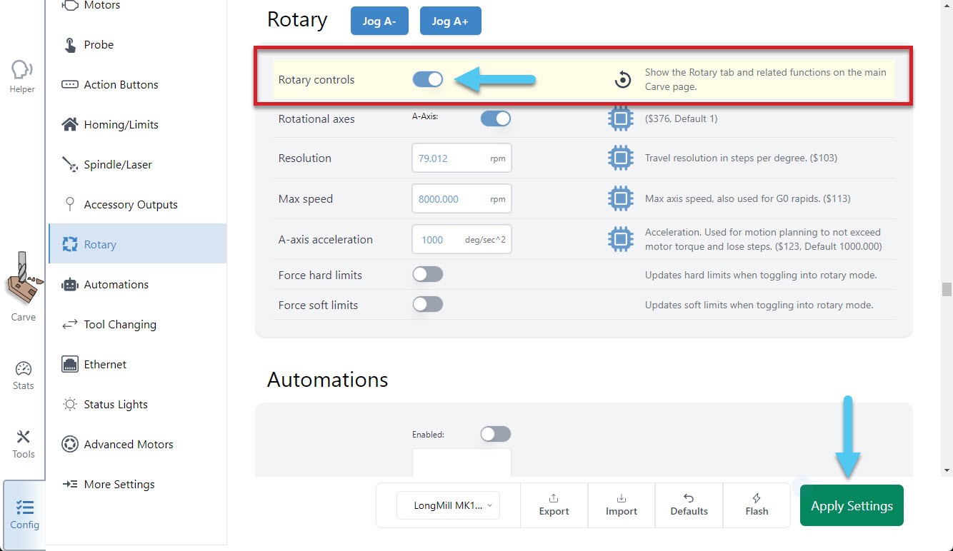
Once done, you will see an additional tab at the bottom right of the main Carve screen, called ‘Rotary’. For 4-axis setups, you’ll immediately have access to all buttons and it’s unlikely that you’d want to switch over to ‘rotary mode’, meanwhile for 3-axis setups you’ll notice that some buttons will be grayed out before you’ve switched to rotary mode, or once you’re in rotary mode. This is because some actions require movement in the Y-axis and others require movement in the A-axis, and since you have a 3-axis machine you can only do one or the other at a time:
- Rotary Toggle – for toggling between Rotary Mode and 4-axis Mode, or if you’re using a 3-axis machine the only option will be rotary mode
- Rotary Surfacing – an easy tool for turning square stock into round stock
- Mounting Setup (Vortex-specific) – helps to drill holes into your wasteboard to mount the Vortex track to your CNC
- Probe Rotary Z-axis – automatically probe to find the Z-axis zero
- Y-axis Alignment – automatically probe to align the Y-axis to the center of the A-axis
Note: you’ll always want to first mount (Mounting Setup) and align (Y-Axis Alignment) your rotary axis before moving forward with any of the other features like: switching to rotary mode, using the jog controls, rotary surfacing, or any other rotary actions.
- Jog Control – You’ll also see new options to rotate the A-axis, go to Zero, set Zero, and adjust speeds
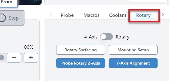
Mounting Setup
When mounting a rotary axis, it’s important to be parallel to the X-axis, and helpful to have a repeatable position so you can reliably mount and unmount the rotary, depending on when you want to use it. If you have your own rotary axis, this is a step that you’ll have to do yourself.
For those who might have our Vortex rotary axis, the ‘Rotary Mounting Setup‘ button is a specific macro that cuts into the machine wasteboard to help you fasten the rotary with perfect parallel alignment. Check out our Vortex Resources for more details on how to use this wizard.
Y-axis Alignment
When switching from regular CNC use to Rotary Mode, you will probe to align the Y-axis along the A-axis. You can do this in the Rotary Tab by hitting the Y-axis Alignment button. Check out our Vortex Resources for more information on aligning your Y-axis when setting up your Vortex.
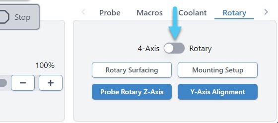
Rotary Mode Toggle
Moreso meant for 3-axis machines, this toggle can only happen once you’ve got your rotary axis set up properly, because after switching it’ll assume you’ve changed your motor wiring to be connected to your A-axis instead of your Y-axis.
The idea is that once you’re in this “rotary mode”, gSender does the legwork to swap firmware settings over to your rotary setup, translate A-axis movements to your machine as if they were Y-axis movements, and as long as you’ve done the alignment and swapped over your wires then your rotary A-axis should now be good to go!
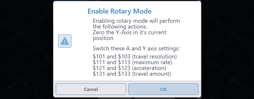
When you enable Rotary Mode, you will see a popup warning you of the changes that will be made by continuing:
- The current position of your Y-axis will be set to Zero
- Your hard limits may be turned off
- Other firmware values might get updated to suit your rotary
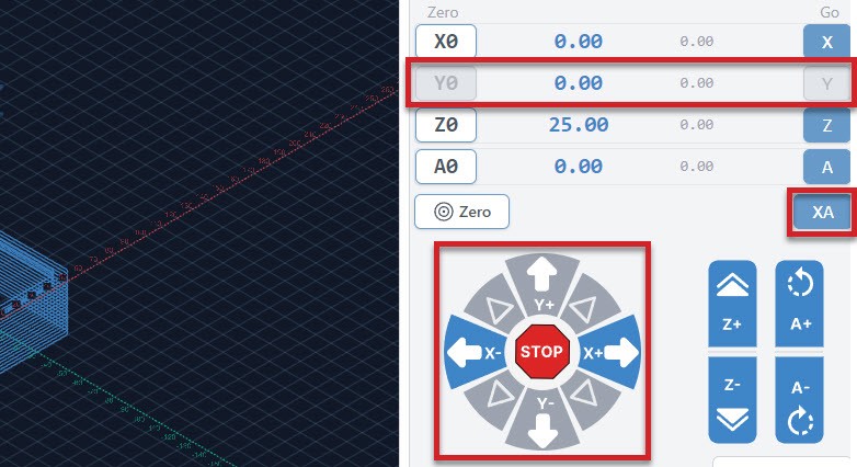
Once enabled, you will see a confirmation appear in the bottom right corner and several changes will happen in gSender:
- The Mounting Setup and Y-axis Alignment buttons will become grayed out
- The Rotary Surfacing and Probe Rotary Z-axis buttons will become available
- The Go buttons for the Y and Z-axes will become grayed out
- The Y0 button will become grayed out
- The ‘XY‘ Go button will be changed to ‘XA‘
- The Y-axis jogging buttons will become grayed out
Rotary Probing
In a similar fashion to regular cnc machining where you set a zero position in relation to the stock you are using, we will do the same when rotary carving. Two differences are that we don’t need to enter a tool diameter and each axis will be set separately.
Setting Z-axis
You can set your Z-axis to either the rotating axis center, or the surface of your stock in a similar fashion to regular CNCing. We recommend using the axis center, as that allows you to make use of the Vortex’s built in Z-axis probing functionality.
To do this, jog the cutting bit to be hovering approximately ~15mm just above the chuck. Double check that your probing wires are in place before proceeding!
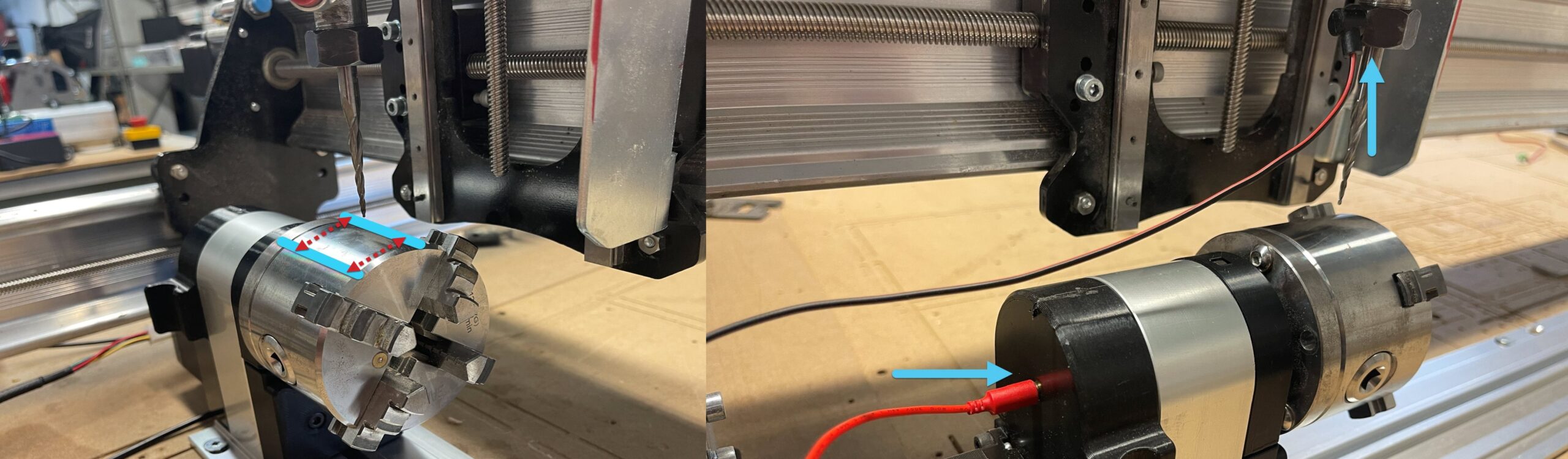
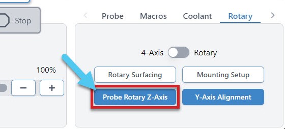
In gSender, select the rotary axis tab, then click ‘Probe Rotary Z-axis‘ and the Z-axis will begin probing automatically, setting the Z-zero point for you. This will need to be done for each tool change in addition to the beginning of each job.
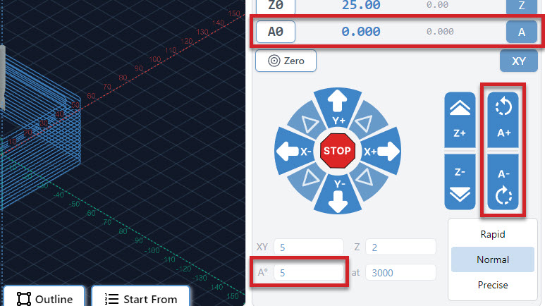
Setting X & A-axis
Setting both the X-axis and the A-axis are done manually.
- To set your X-axis, jog to wherever you’d like the job to start then click ‘X0‘ to set your X-zero point. Make sure this is far enough from the chuck to ensure there won’t be any collisions with your cutting bit, workholding or screws.
- To set your A-axis, simply click ‘A0‘ at the beginning of each job, under the Rotary Jog Controls. Note that if this isn’t done, the rotary will spin back to zero before the job starts.
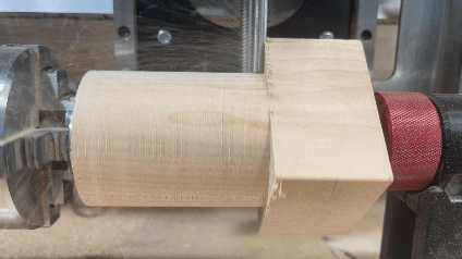
Rotary Surfacing tool
he Rotary Surfacing button will allow you to turn square stock down to a cylinder. We recommend using a ¼ inch upcut end mill for turning stock, as it’s the most efficient.
Now you will see the Rotary Surfacing Tool. Here you will enter details about your stock length, start and final dimensions. You will also see spots for Bit Diameter, Step over, Spindle RPM, and Feed rate.
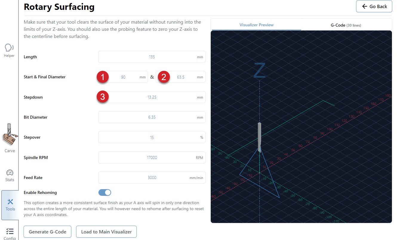
Rotary surfacing is similar to the regular XYZ surfacing tool. Let’s explore this a bit further.
- Your start diameter is the largest diameter on your stock. Usually this means the diagonal distance from opposite corners if you’re starting with square or rectangular stock.

- Your final diameter is determined by the short side of your stock.
- With a starting height of 90mm and a finished height of 63.5mm, we are removing 26.5mm of material. However, since we have the Z-axis set at the center of the material, we will need to divide that 26.5mm in half. We are basically taking 13.25mm off of the top and the bottom. If you want a single pass, your step down would be 13.25mm. Dividing that by two and setting the step down to 6.625mm, means that we will be doing two passes. This will produce a piece of round stock with the maximum diameter possible.
(Start Height – Finishing Height) / 2 = Total Step down for ONE pass
Rotary Settings
When you go to Config ➜ Rotary, you’ll be able to enter your own settings, reset the default settings and turn Hard Limits on/off.