
Congrats on upgrading to our newest and most powerful CNC controller to date, the SuperLongBoard!
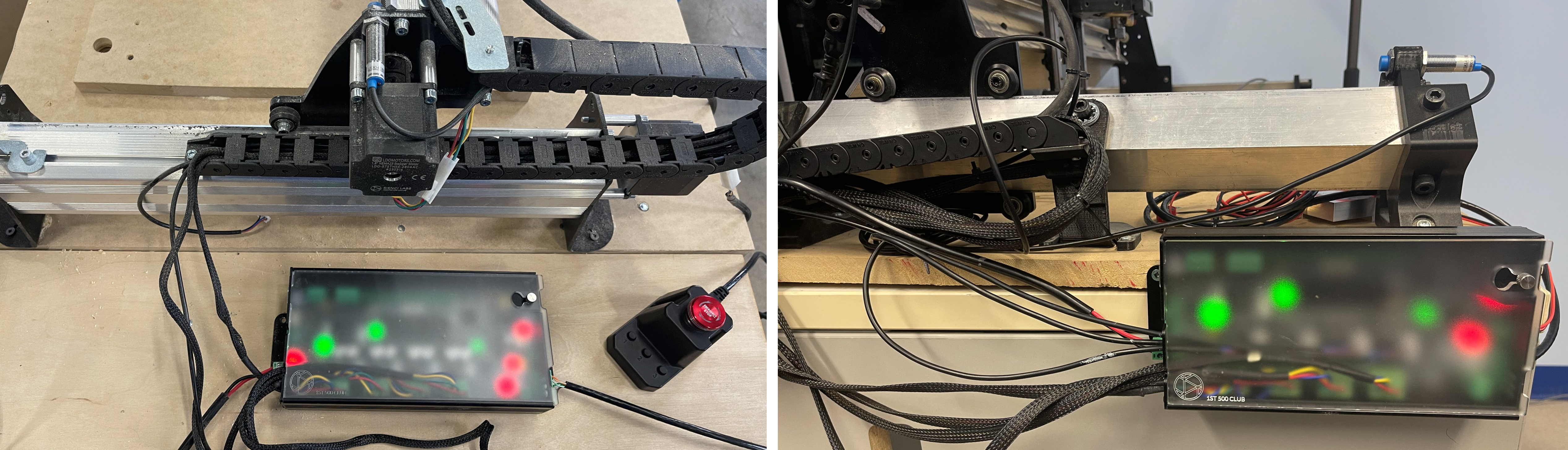
Our main goal in this section is to have you go in with a working CNC, then leave with an SLB-boosted machine without skipping a beat. This guide will be mostly written with LongMill owners in mind who have the older LongBoard (LB, pictured on the left) that they’ll be swapping out for the SuperLongBoard (SLB, on the right), though there will be minimal differences for other CNC owners with a LongBoard. If you’re swapping from the CNC xPRO V5 controller, we have a separate writeup for that here.
Unpacking
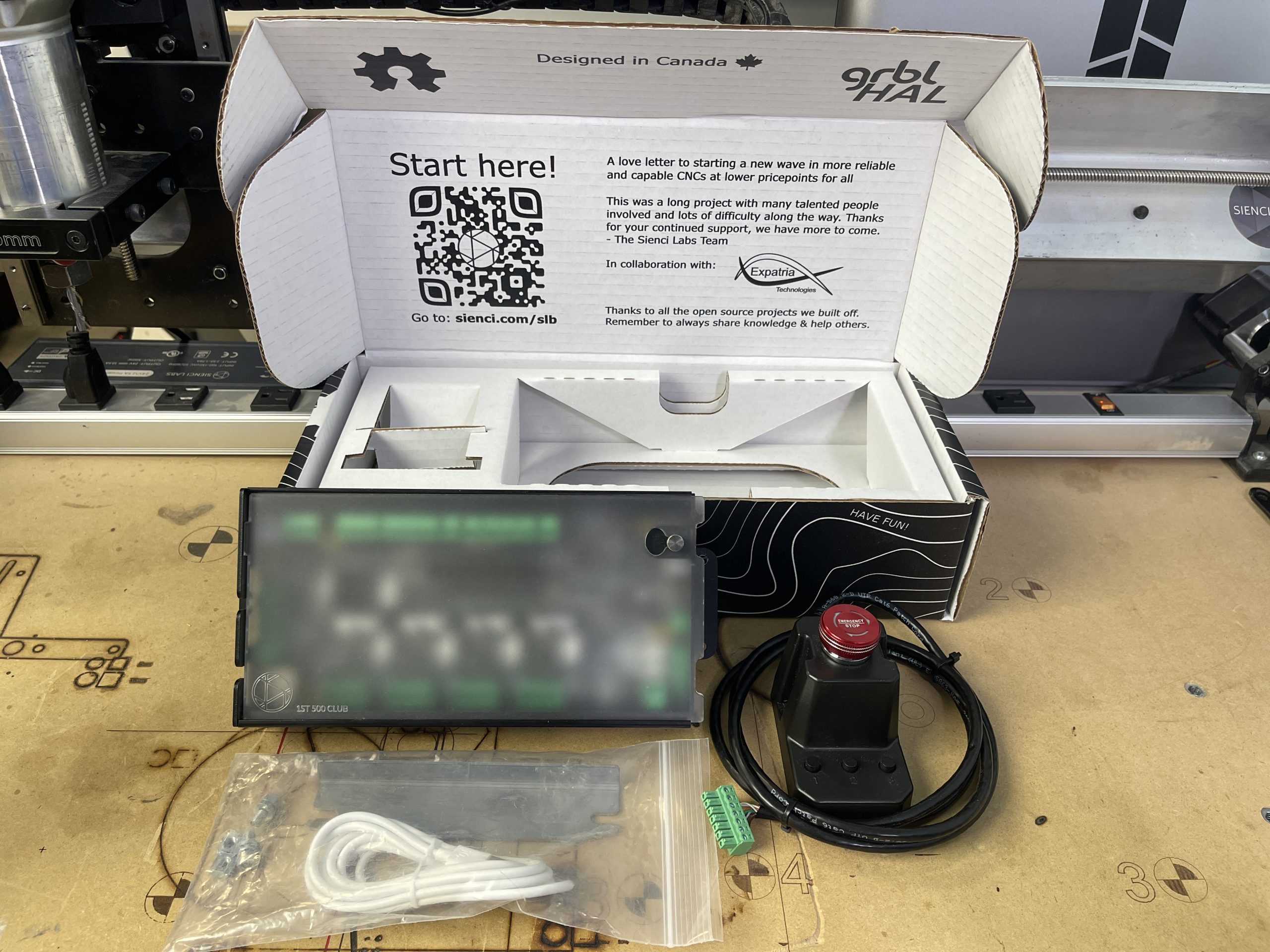
In the box you’ll find:
- Your new SuperLongBoard inside it’s aluminum enclosure
- E-stop with 3 additional ‘Action Buttons’ that are customizable
- E-stop cable, plenty long to increase mounting options
- And a USB-C cable, MK2 mounting hardware, and some spare connectors
The only other parts that you’ll need to supply yourself are:
- The minimum 24V 10A power supply needed to run the SLB (you can use the one your LongBoard currently uses)
- Your CNC machine, already tested to be working using its existing LongBoard
- A computer running gSender with a free USB port
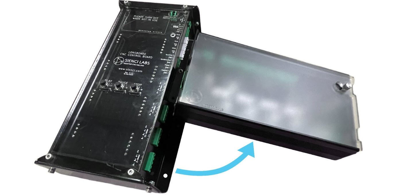
We hope everything arrived well and in one piece! Let’s take the cover off the SuperLongBoard and see what’s under the hood.
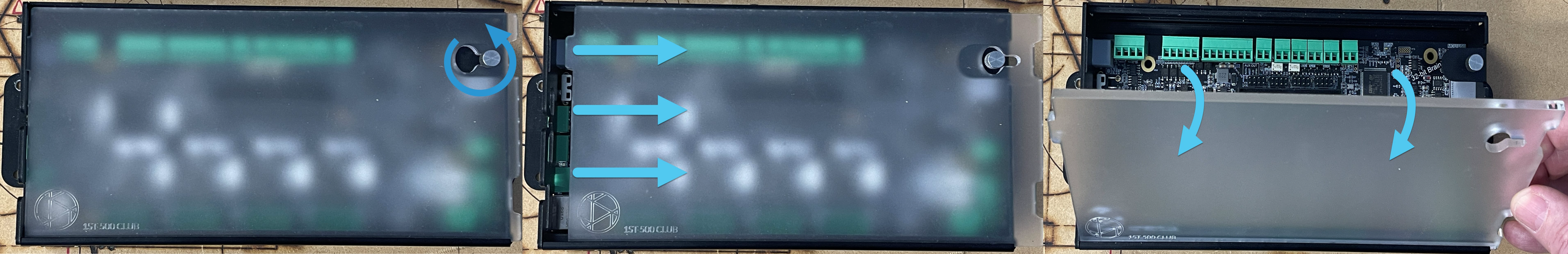
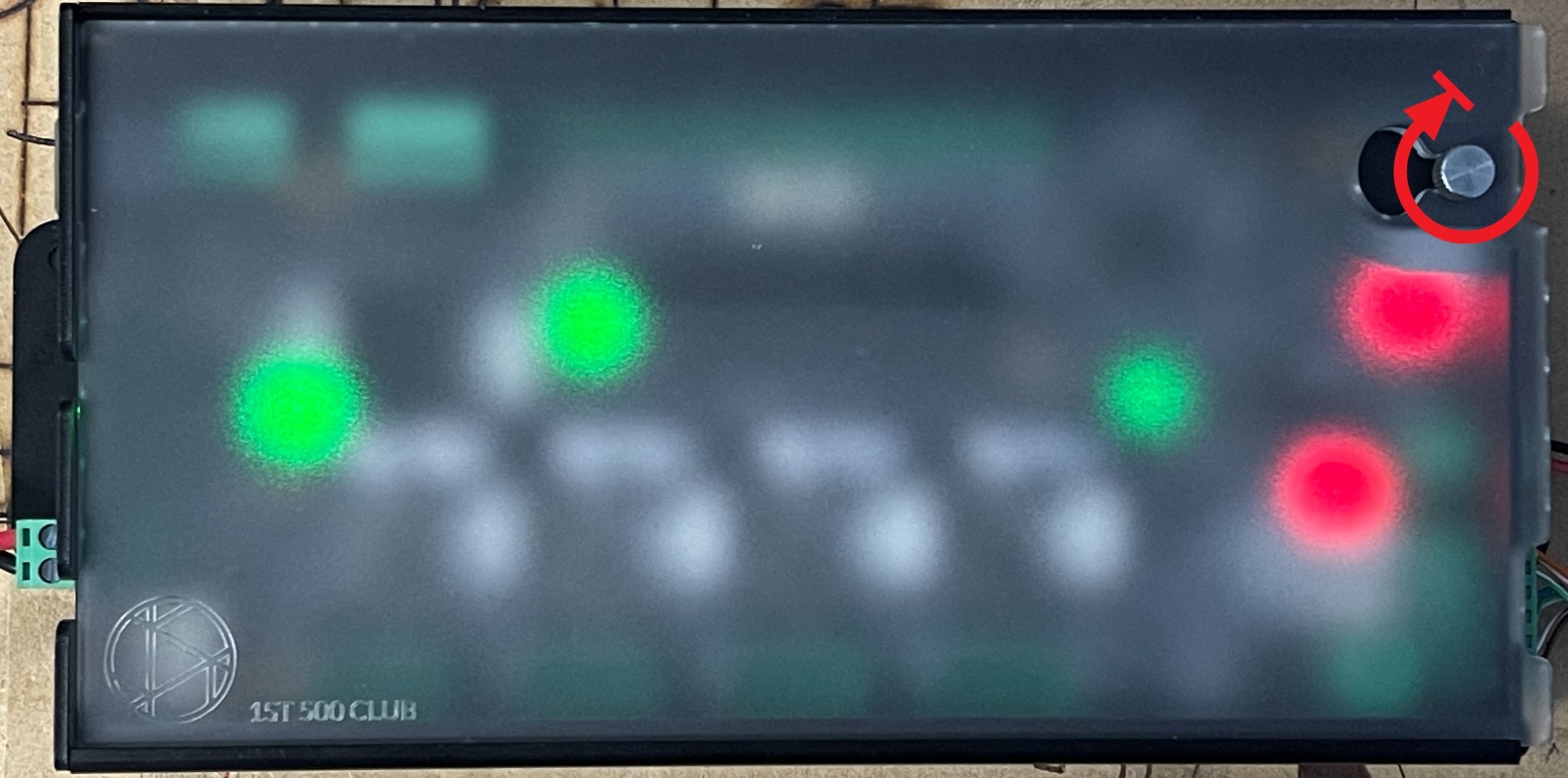
Unscrew the top-right thumbscrew a couple turns (pictured) then slide the cover to the right. Once the hole in the cover lines up, you’ll be able to pull the top of the cover towards you and it will come free.
Preparation
Before diving into rewiring, we’d first suggest you note down any firmware changes that are unique about your setup.
Current
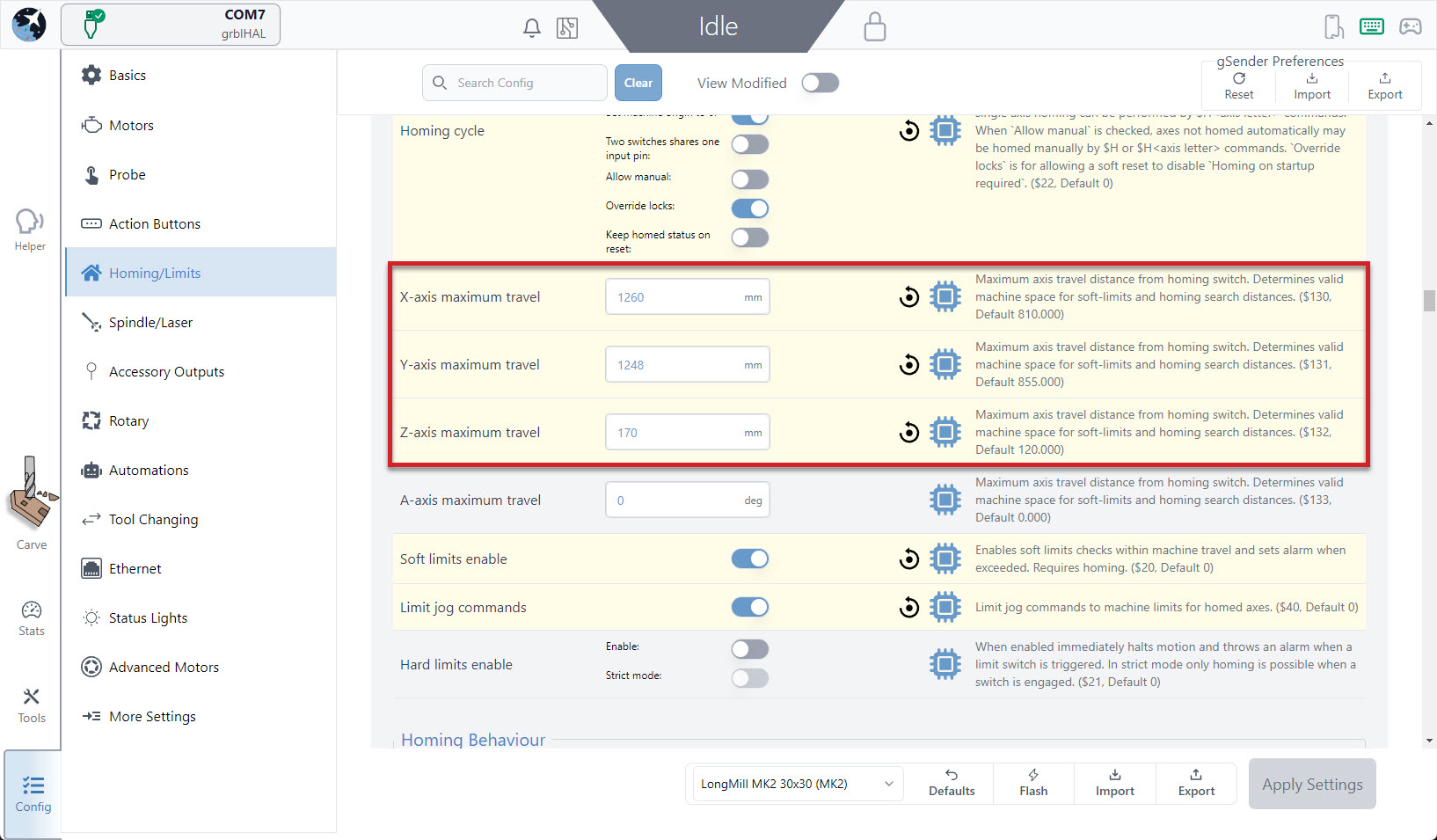
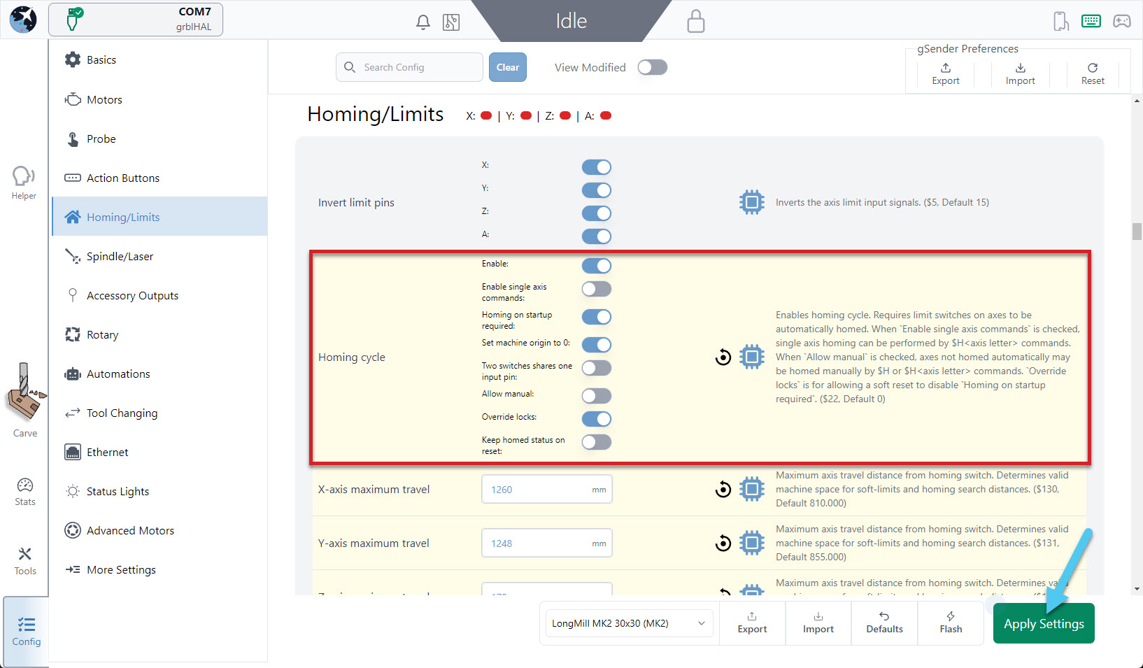
You can do this by connecting to your CNC in gSender and using the Config tab to find sections that are highlighted in yellow. In the example below, you can see that the X and Y maximum travel is different from the standard MK2 30×30.
Classic gSender
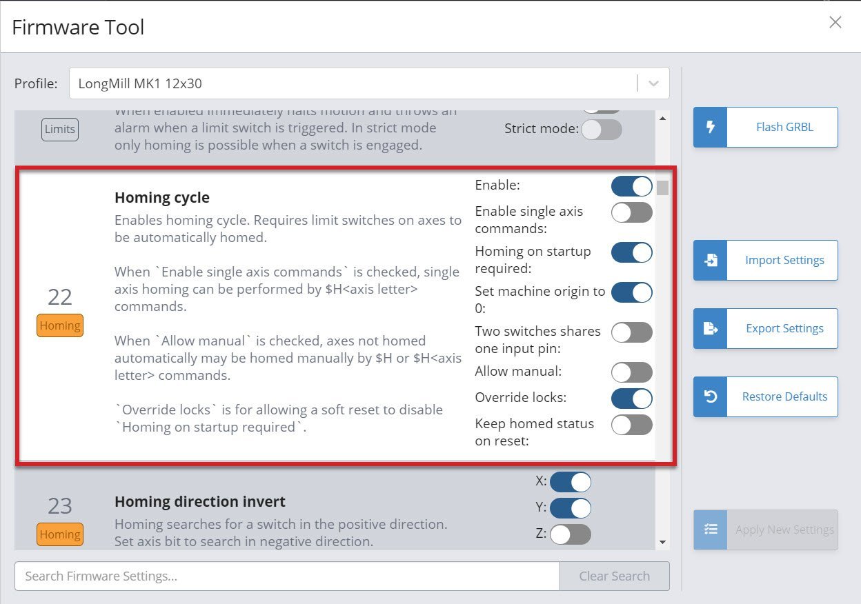
You can do this by connecting to your CNC in gSender and using the Firmware Tool to find sections that are highlighted in yellow. In the example below, you can see that the maximum travel is different from the standard MK2 12×30.
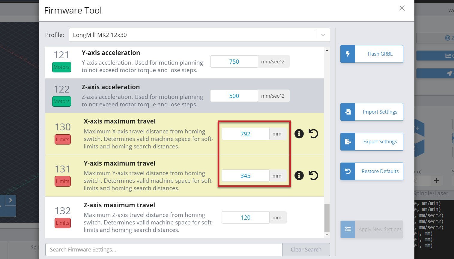
Yellow sections show when a change has been made from the default settings. Any of these should be written down and will be re-entered when the new board is set up.
Wiring
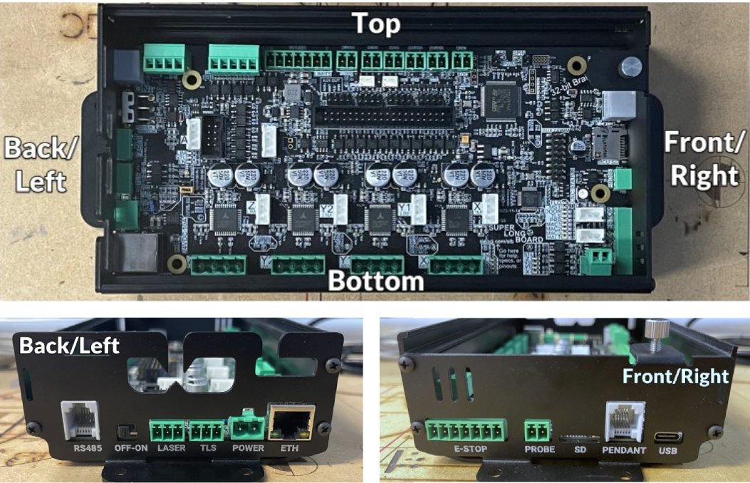
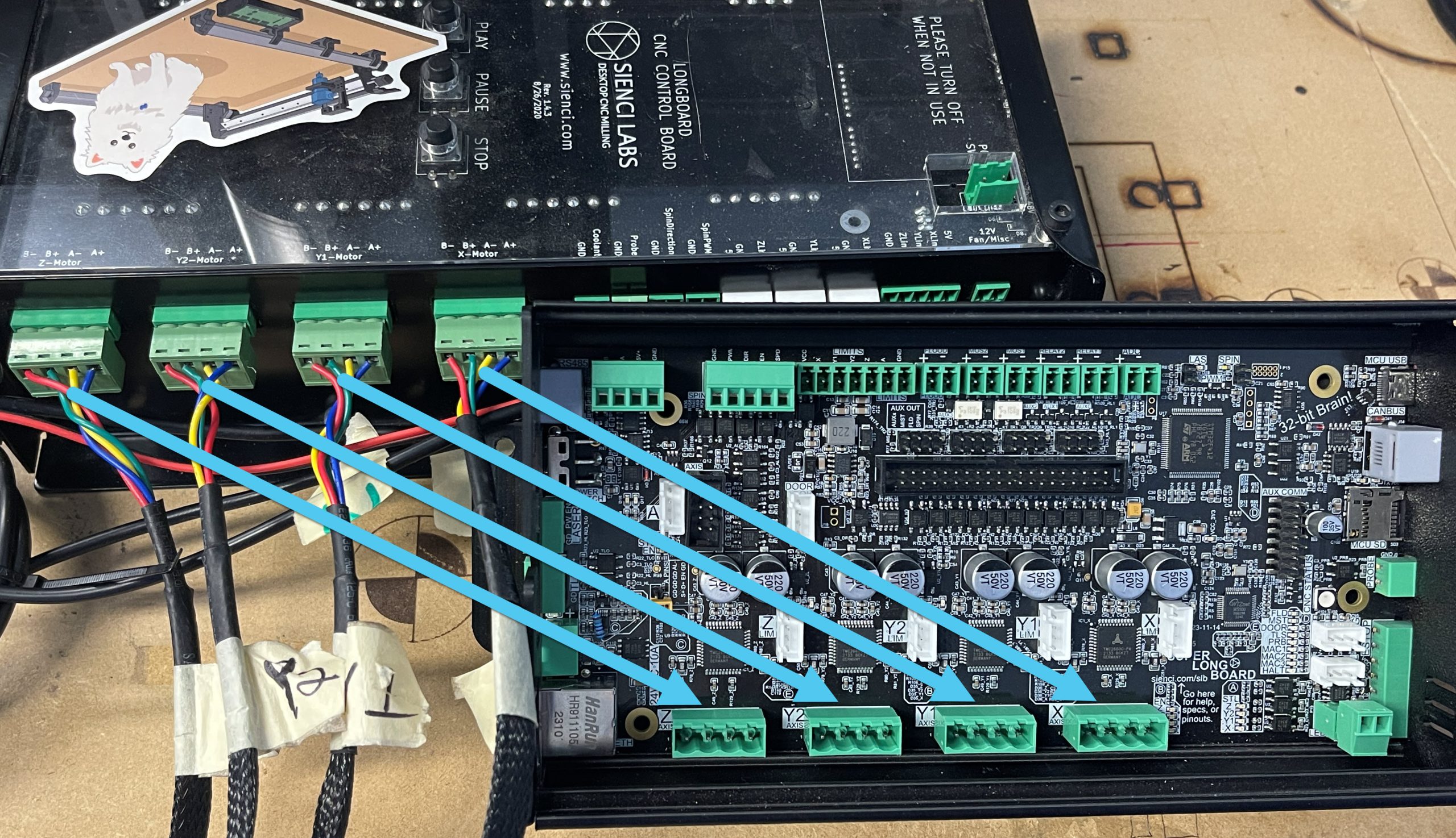
To help communicate where things are on the board, we use the terms shown below:
Let’s start moving plugs over to the SLB!
-
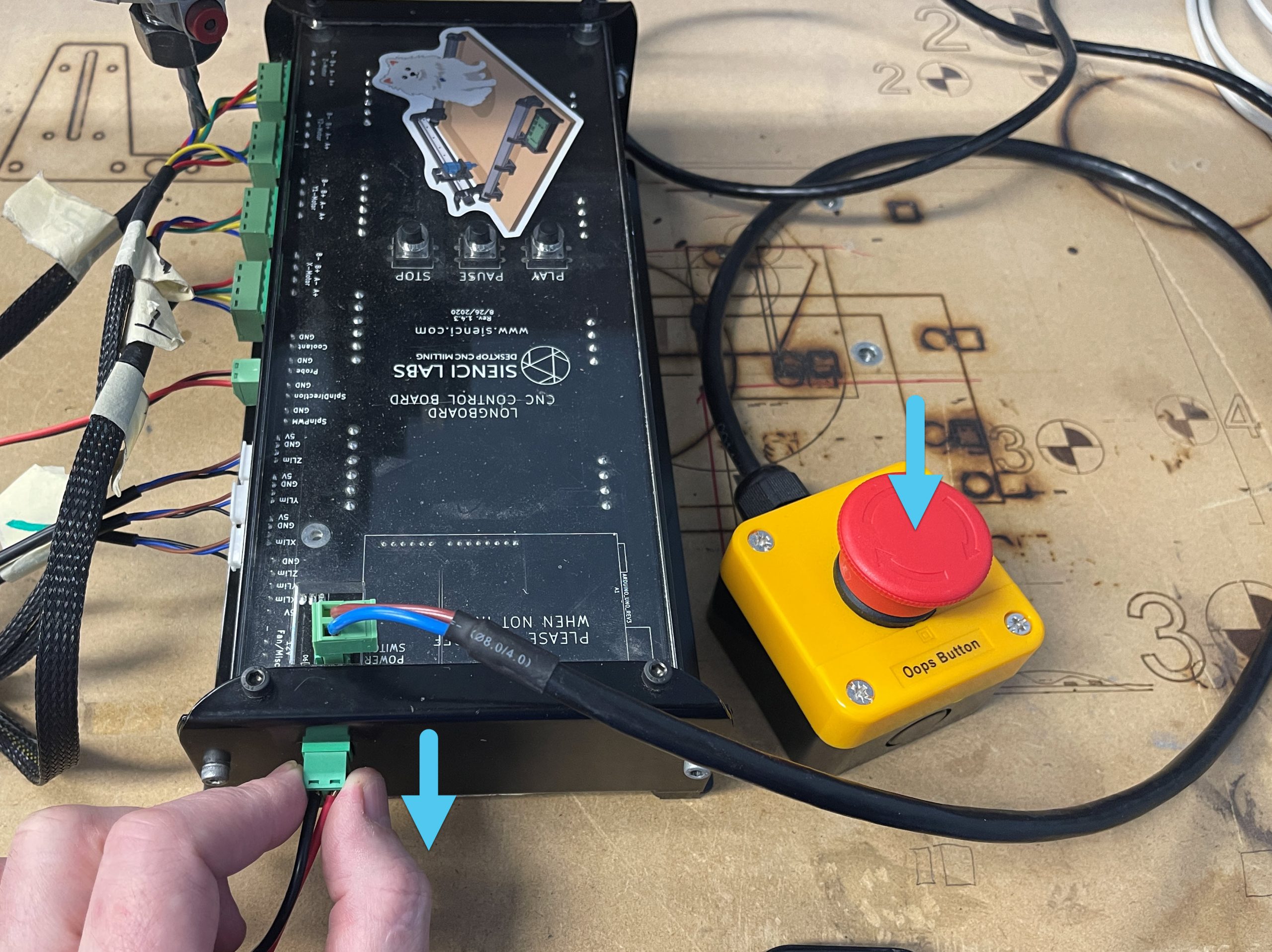
On your LongMill, hit the E-stop then unplug the power cable from the board.
-
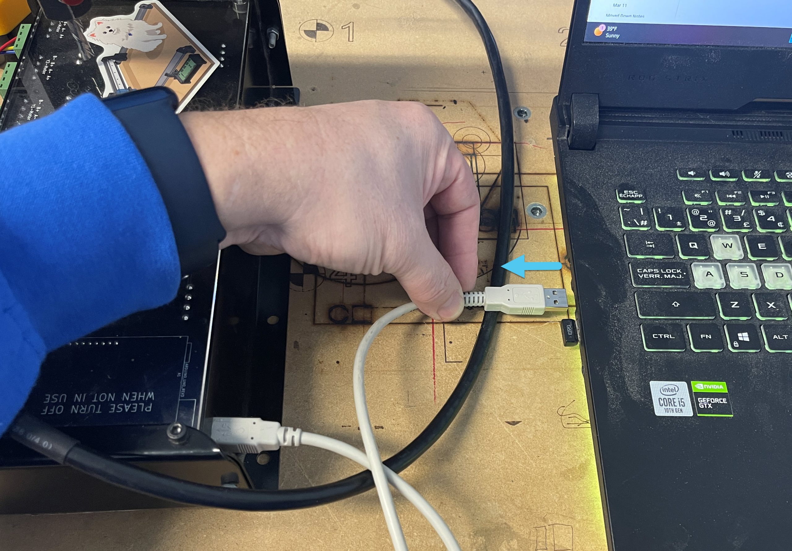
On your computer, unplug the USB cable that ran to the LongMill.
-
Unplug the X, Y1, Y2, and Z connectors from your LongMill and plug them into the SLB in the same order. There aren’t any extra steps you have to do even if you have the Vortex (as long as it’s the open-loop type with the rotary switch).
-
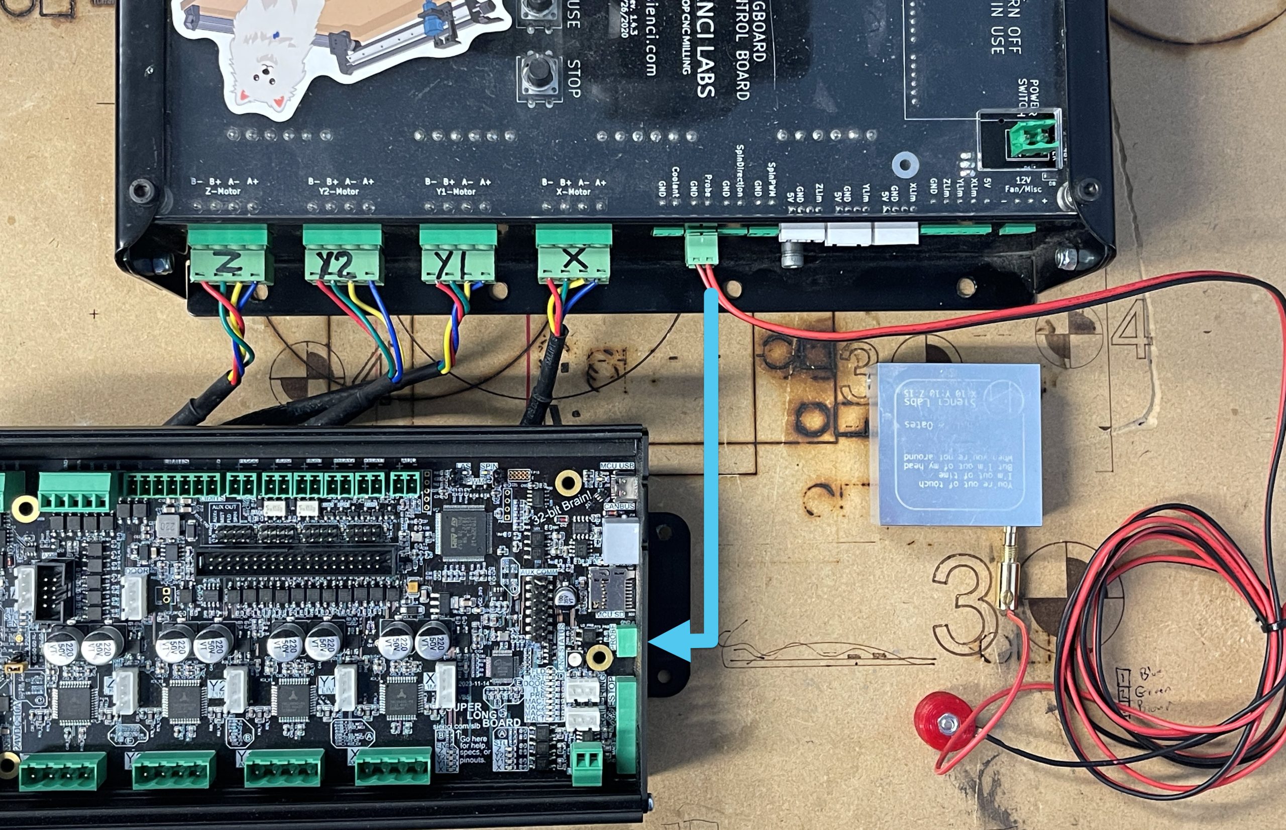
Unplug your touch plate/probe from the LongMill and plug it into the SLB, on the Front Side.
-
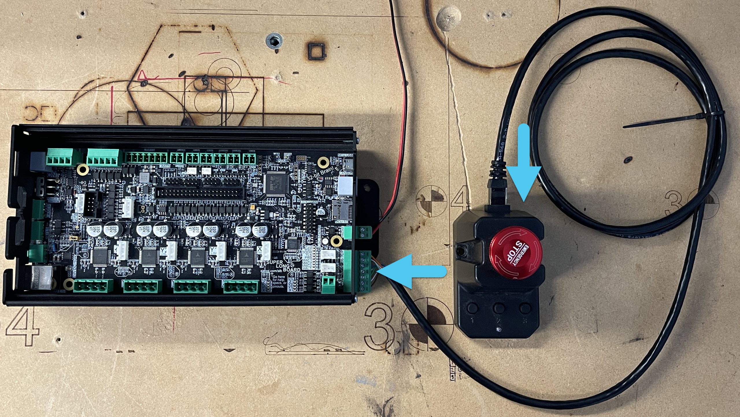
Grab the new E-stop and plug the green end into the Front Side of the SLB, then the other end into the backside of the E-stop.
-
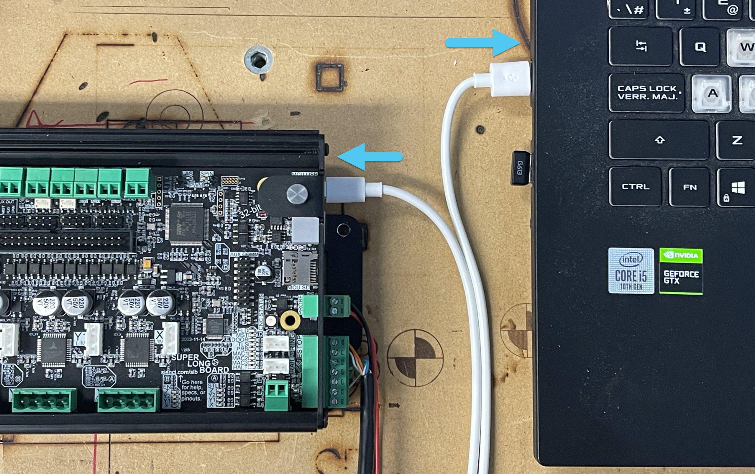
Now grab the USB-C cable that came with your SLB and plug it into the Front Side of the board. Plug the other end into your computer.
-
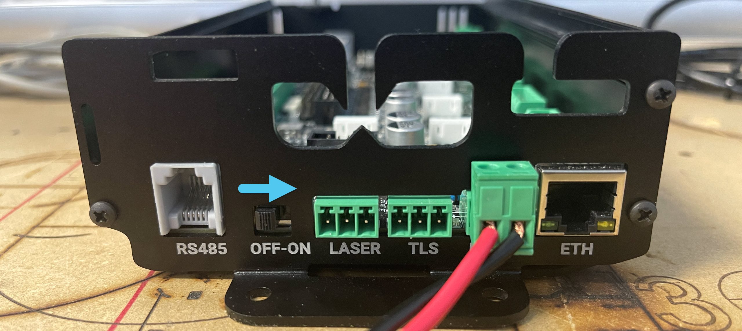
On the Back Side of the SLB, plug in the power plug that we unplugged from the LongMill earlier.
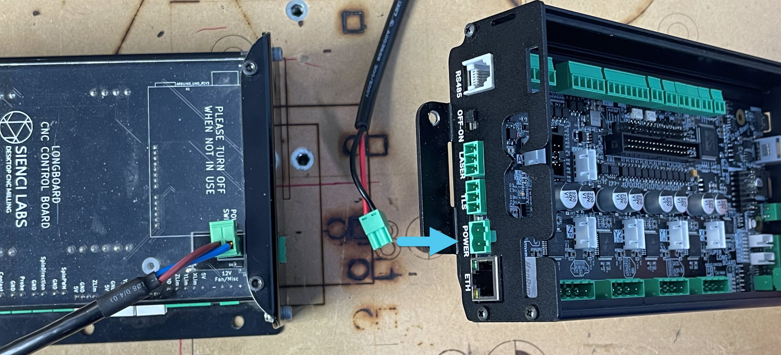
-
Lastly, when looking at the Back Side of the SLB, you will see a power switch. Slide it to the ‘ON’ position to power on the SLB. It’s Alive!!
Congratulations! You’ve wired up your new SLB with all its typical accessories! If you still have other, slightly less common accessories to wire in, then keep reading the next section; otherwise you can move over to gSender to connect and do some quick tests.
Optional Wiring
You have your SLB wired up and ready to go, but do you have:
- Limit Switches?
- A (pew pew) LaserBeam?
- An IOT Relay working to turn on your shop vac or router?
If so, this section is for you. Fear not, we’ve got you covered!
Limit Switches
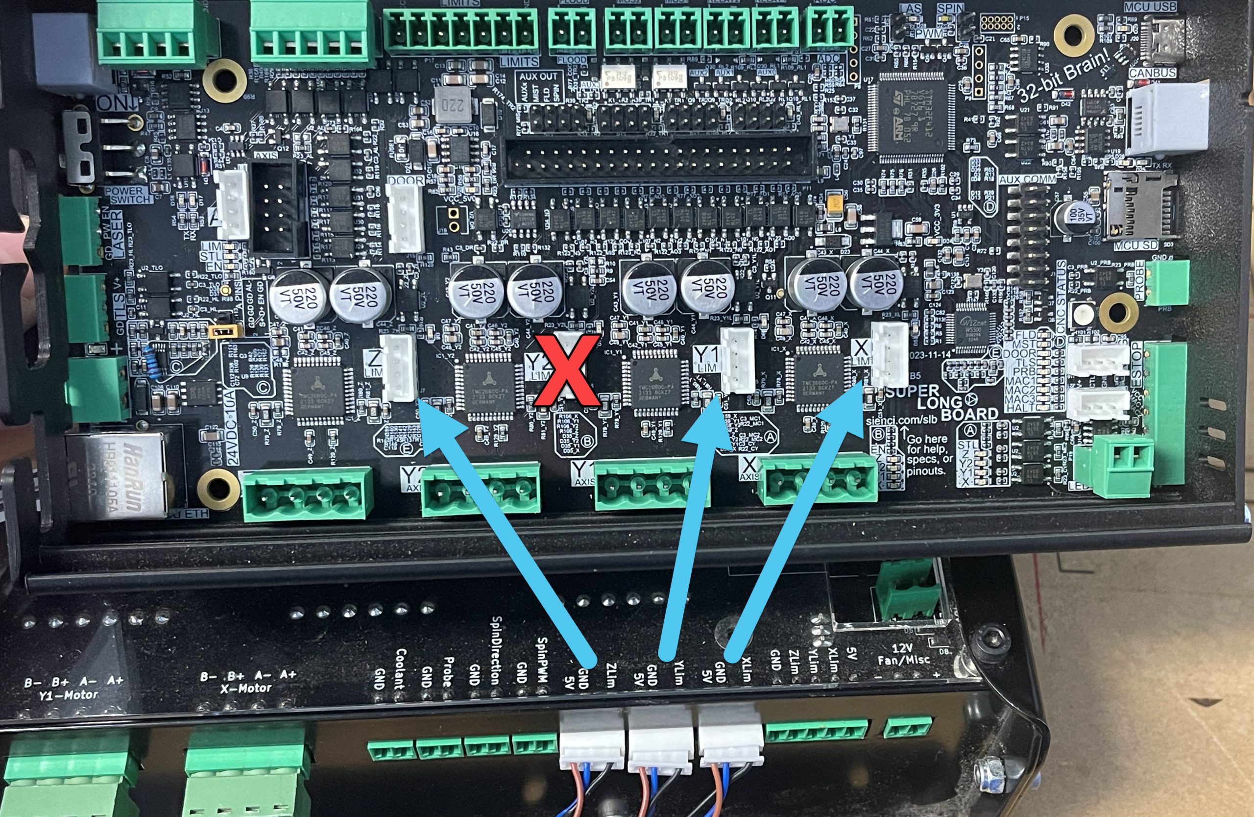
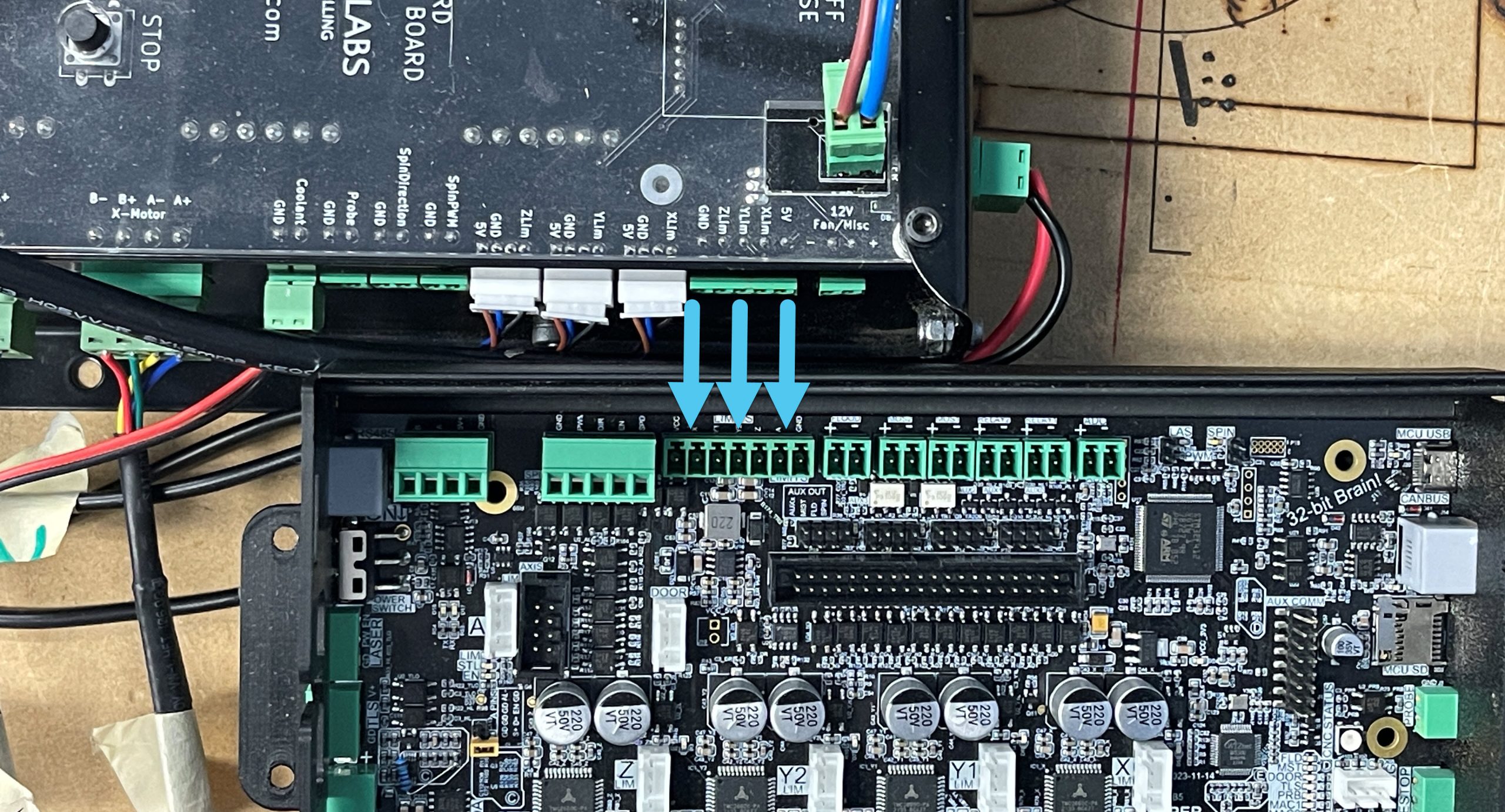
Sienci inductive sensors can be plugged straight into the white JST connectors, so you can simply unplug them from your LB and plug them into the corresponding spots on the SLB.
Note: The Y2 connection isn’t used at this time
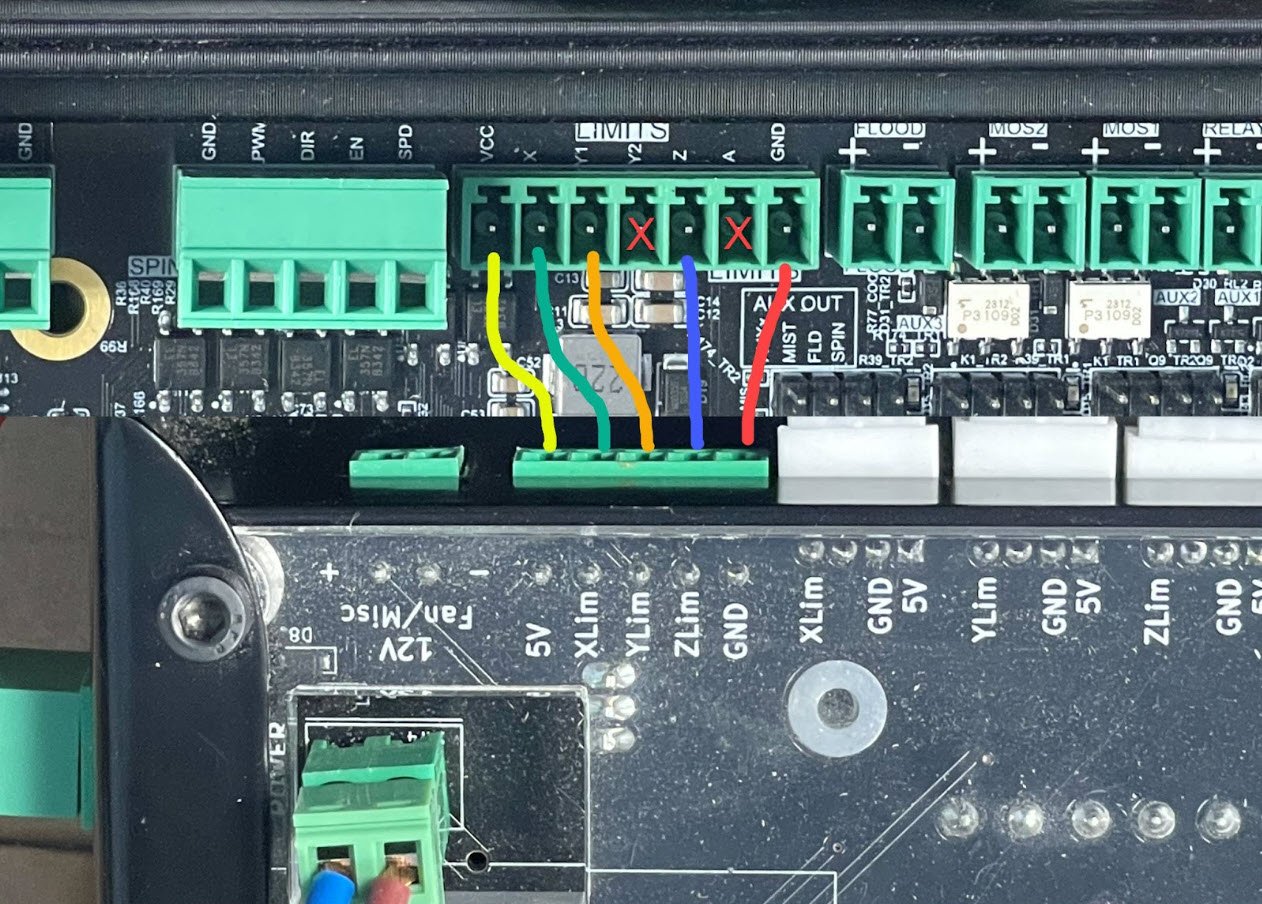
If you are not using the Sienci inductive sensors, wire your sensors in using the Auxiliary terminal connector input.
The hookup changes for this new plug, compared to the one we had on the LongBoard, is shown below. Don’t worry about the Y2 or A-axis wiring for now.
LaserBeam
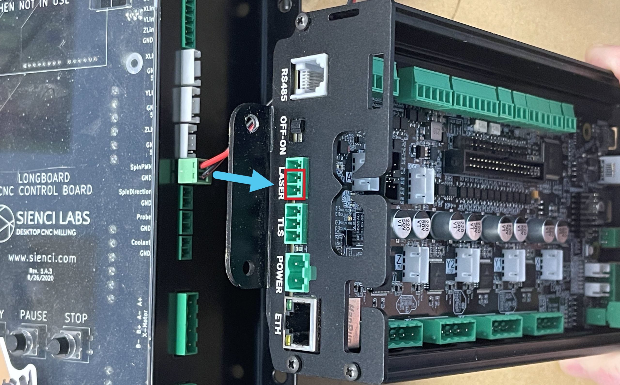
On the LongBoard, unplug your 2-pin SpinPWM plug and plug it into the 3-pin Laser plug on the Back Side of the board. Ensure that you plug the two plug connector into the bottom/far right two pins, as indicated in the pictures below.
Warning: Lasers are very dangerous devices that can instantly damage your vision and cause fires. Become knowledgeable on staying safe by reading documentation by your laser manufacturer, the SLB, how laser mode in grbl & grblHAL works, and how your g-code sender handles laser commands. Even then do not become complacent; continue to treat your laser with caution and respect and turn off power completely to the laser driver when you’re not using it. You can never be sure when the laser might fire unexpectedly and hobby equipment and software can be imperfect. If you have the driver turned on, everyone around should always be wearing eye protection and there should also be clear warning or signage to protect others.
Spindle
If instead you had a Spindle connected to your LongBoard and would like to swap it over to the SLB, just continue through the initial setup steps for now then when you’re ready swap over to the explanation for Spindle wiring in the full SLB Manual.
Rotary Axis
As stated above, if you have the original Vortex setup with a rotary switch and open-loop motor then there’s no additional wiring that’s needed outside of just transferring over your motor wires. If you’re trying to set up your own custom rotary axis that doesn’t have a switch to share motor signals with the Y-axis, then you might want to read typical wiring setups here.
IOT Relay
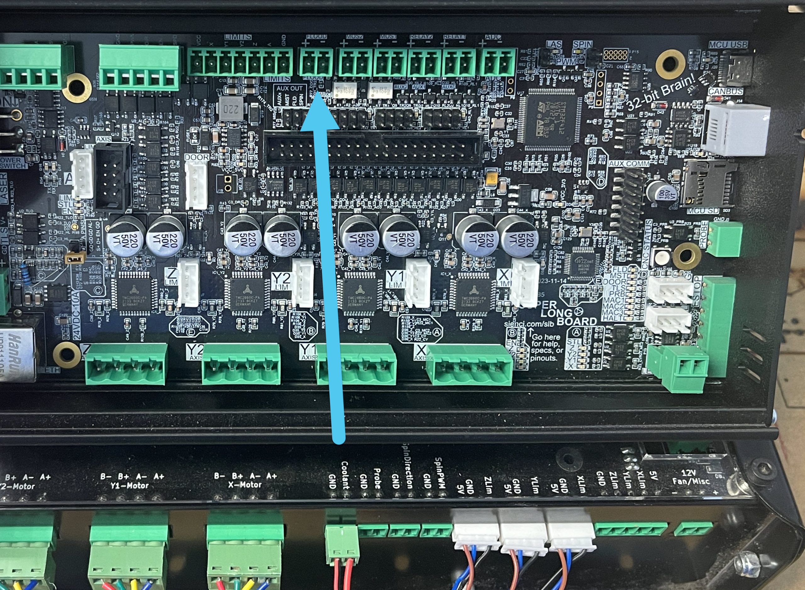
Simply unplug your 2 pin connector from the Coolant on the LongBoard, and plug it into the Flood connector at the top of the SLB.
gSender
The SLB requires use of version 1.4.0 or later, only these versions can talk to the SLB. Please keep up to date with installing the latest version of gSender here.
Connecting to your SLB
You will be connecting to the SLB differently than you are used to. Remember to power on your board before starting this process.
Current
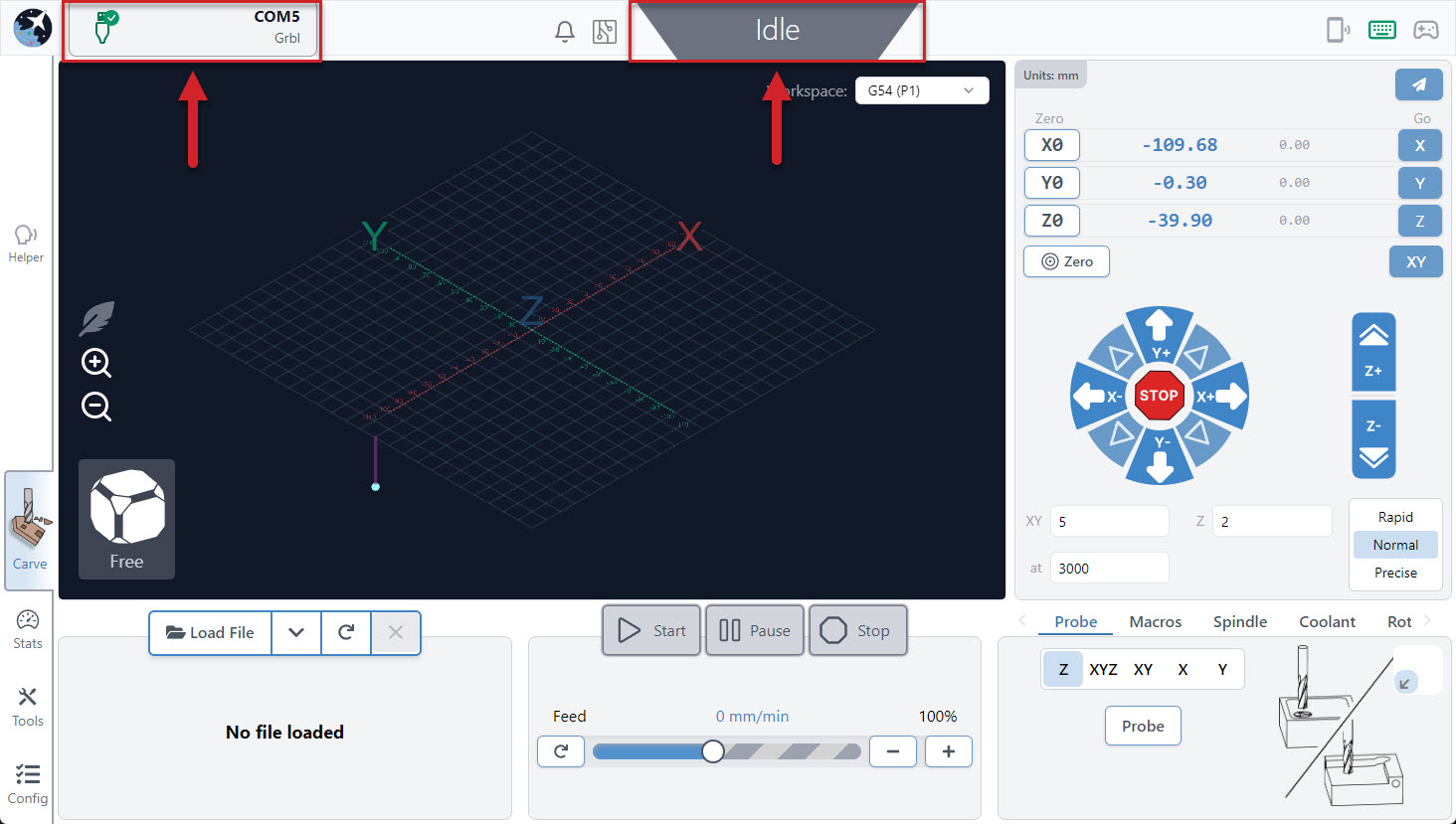
Hover over the Connect to CNC button at the top left corner of the screen and click the first option (connect this way on your first setup even if you’re planning to use Ethernet in the long-run).
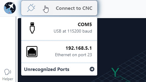
After a moment you should see the plug icon turn green with a checkmark, the status bar at the top, middle change from Disconnected to Idle, and all the controls in the app become coloured indicating that they’re ready to be used.
If you don’t see all these changes happen, we’d recommend you check a couple things then retry:
- You have a secure connection between your machine’s control board and computer.
- Click the ‘Connect’ button again to Disconnect, then hover over it to check if there are any other options listed that you can try. For some CNCs you might have to check the ‘Unrecognized Ports’ dropdown then help us update our list of recognized CNCs.
- Ensure that any other programs that could be talking to your CNC are closed (ex. UGS).
- If it’s connecting but behaving oddly, gSender’s automatic firmware detection might’ve failed. In this case ensure you set your board’s correct firmware as grblHAL under Config ➜ Basics ➜ Firmware fallback.
Classic gSender
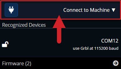
- Go to Connect to Machine in the top left corner.
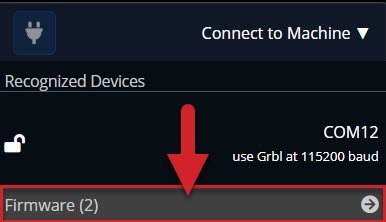
- Connecting to the SLB, requires you to select a new button. Click the gray bar at the bottom labelled Firmware.
- Then click on grblHAL.
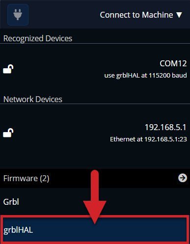
- With the SLB, we have the option to connect via USB or Ethernet. Under Recognized Devices there should be one option, let’s select that.
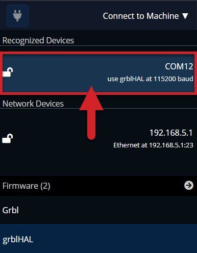
Congrats! You have connected to your new SuperLongBoard!! Since USB is plug and play, we’ve selected it now and can connect via Ethernet at a later time.

Let’s move on to some quick tests.
Quick tests
Now that we have the basics plugged in and are connected in gSender, we’re going to test out a couple things. This will help catch any issues before the SLB is more permanently mounted or you start on your wire management 😉 . Let’s put this SLB through some paces eh?!!
Power On Test
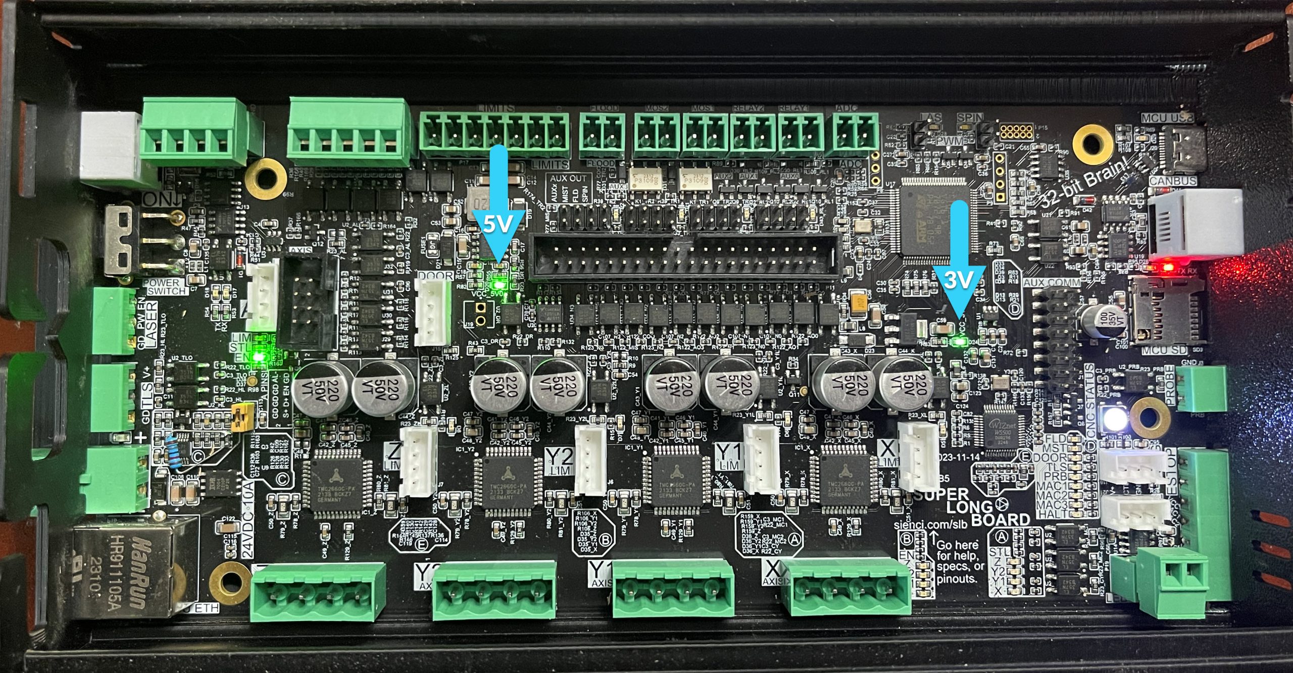
When the board is receiving power, you will see two specific green lights come on. One shows you that your 5V power is active, and the other shows that your 3.3V current is working.
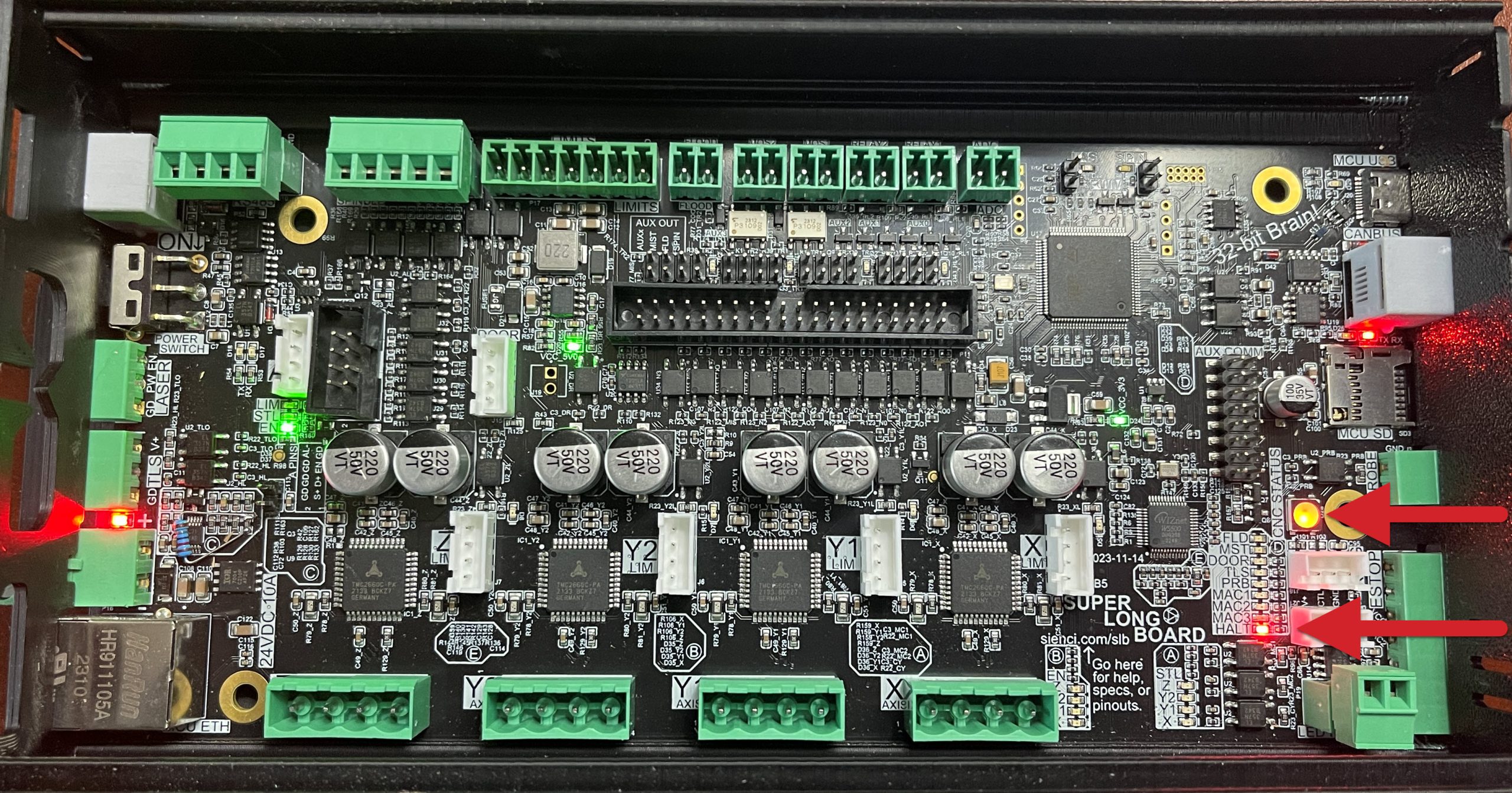
Now hit the E-stop button (it may already be pressed down). When you press it down, the E-stop button will go dark and power to the motors will be cut.

The SLB will respond by turning several lights RED. Most notably your CNC Status light and a very small led called HALT will both turn red.
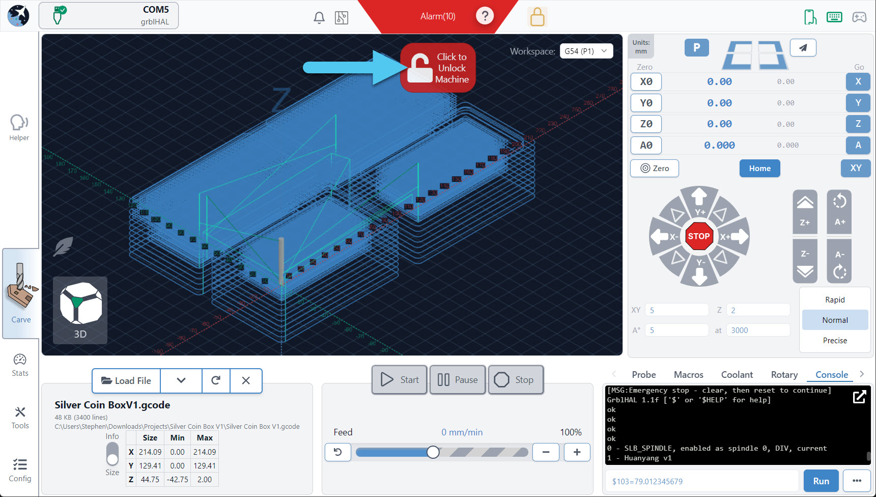
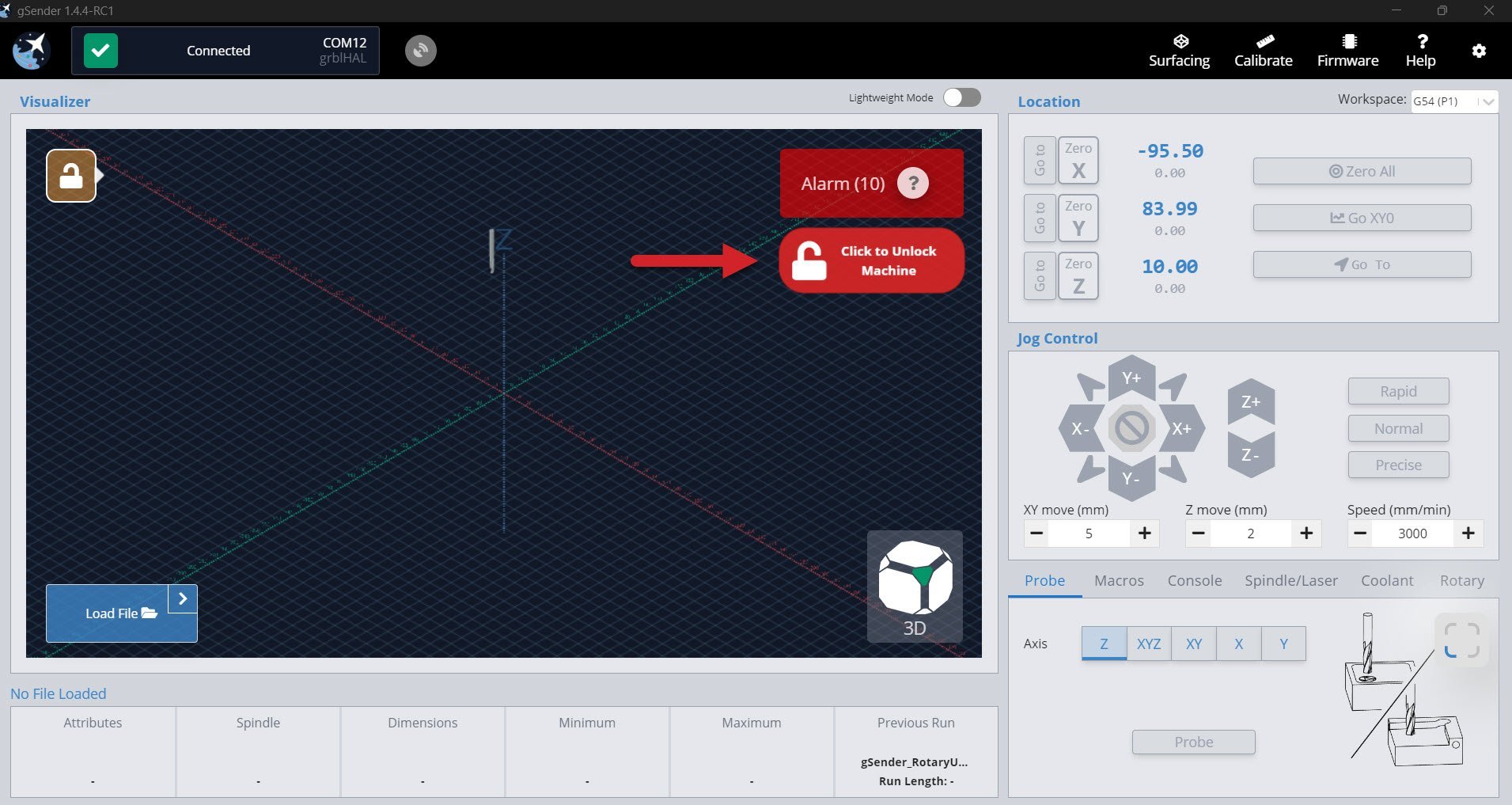
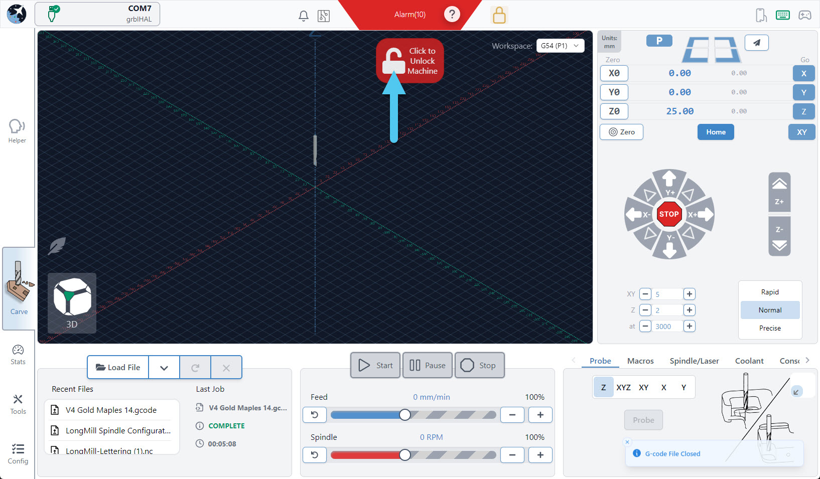
Now we can deactivate the E-stop button by turning it clockwise until it’s raised again. You will see the E-stop button light come back on when raised correctly. We will need to unlock the SLB in gSender by pressing the Click to Unlock Machine button.
Congrats! You’ve completed the Power On Quick Test.
If your lights didn’t come on or you experienced unusual behavior:
- Check that the power supply is plugged into the wall, the brick, and the board
- Ensure there is a light on the power supply (our new blue power supplies don’t have one)
- Ensure the SLB power switch has been flipped to be ‘ON’
- Ensure there are lights on the board
Move Test
Testing Directions
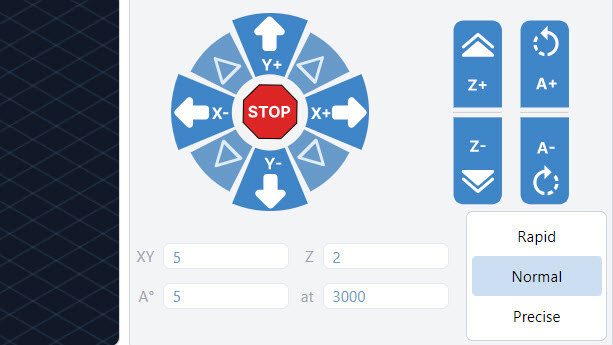
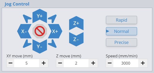
It’s time to take the SLB out for a spin! Using the jog controls on the main page of gSender, try moving your machine around in the X, Y and Z-axes. Make sure they’re going in the correct directions; also try increasing the jogging ‘Speed’ value to 5500mm/min (220ipm) to test the faster default capabilities of the SLB.
Note: If you have a LongMill MK1, you’ll need to invert your Z-axis movement (see next step).
Current
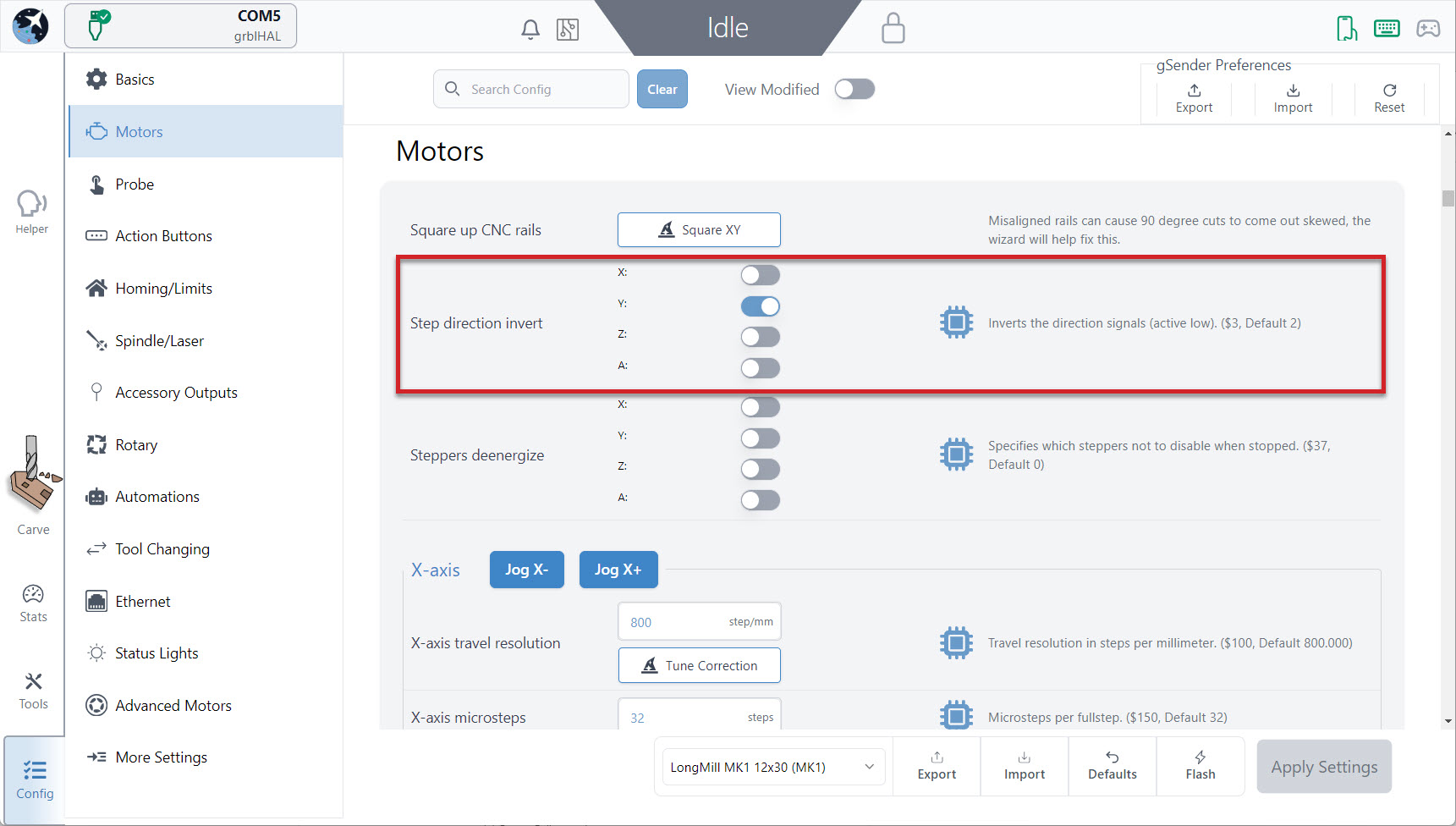
If you find that your axes are not moving in the correct direction, you can go into the Config tab and change the axis that’s wrong. Also, if you notice that your CNC reacts intermittently at higher speeds then you might have to either spend some more time tuning your machine’s mechanics, or consider lowering the SLBs maximum speed with settings 110, 111, and 112.
Classic gSender
If you find that your axes are not moving in the correct direction, you can go into your firmware settings and change the axis that’s wrong. Also, if you notice that your CNC reacts intermittently at higher speeds then you might have to either spend some more time tuning your machine’s mechanics, or consider lowering the SLBs maximum speed with settings 110, 111, and 112.

If you’ve done ‘movement tuning’ of your CNCs steps/mm ($100-102), you can transfer these over to the SLB. When you do this remember that:
- The LongBoard used 1/8th microstepping (or find what you were using if switching from another board)
- The SLB uses 1/32nd microstepping by default (x4 more precise)
- This means you’ll want to take your old values and multiply them by 4 when you add them to the SLB. For example the old value might be 201.5, so the new one should be 806 steps/mm
- Once added, you can double-check that the movement distances look correct
While you’re here, if you used to use $1=255 to hold your motors (typically used for heavier spindles or CNCs mounted vertically), you can now instead scroll down to setting 37 “Steppers de-energize” where you can now choose to hold individual motors.
Touch Plate Test
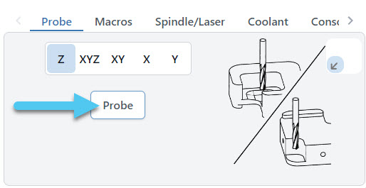
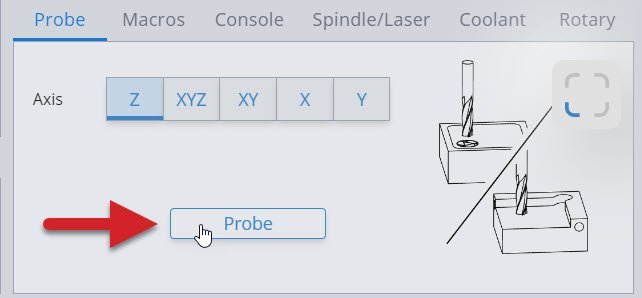
One last test is to check that your touch plate works. Navigate to the Probe tab and hit the ‘Probe’ button.
Then, tap the magnet to the touch plate. You will see the yellow PRB light on the SLB.
You’ll know you are successful if the popup button turns blue, and says “Start Probe”.
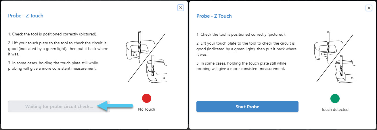
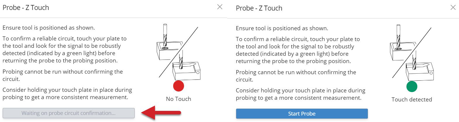
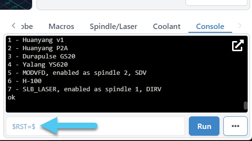
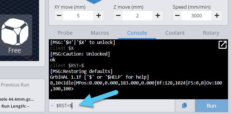
If the light is coming on but the popup button isn’t turning blue, this can sometimes be fixed by resetting your board settings. Do this by typing $rst=$ into the console tab and hitting Enter, then use the power switch on the back of the board to “power-cycle” it off and back on again. Once you reconnect in gSender you can try probing again.
Note: If you reset your board settings, you’ll need to go back and change any other settings you changed up until this point,, like inverting the Z-axis for MK1 owners.
Congrats! Your Quick tests are now complete. This means that all our basic accessories should now be set up and ready to use on your new SLB! If you wired up other accessories then keep reading the next section to ensure you test them too, otherwise you can move on to the Routing section.
Other Tests
Limit Switch Test
Your limit switches are installed and plugged into your SLB, so let’s check that they are working properly.
Current
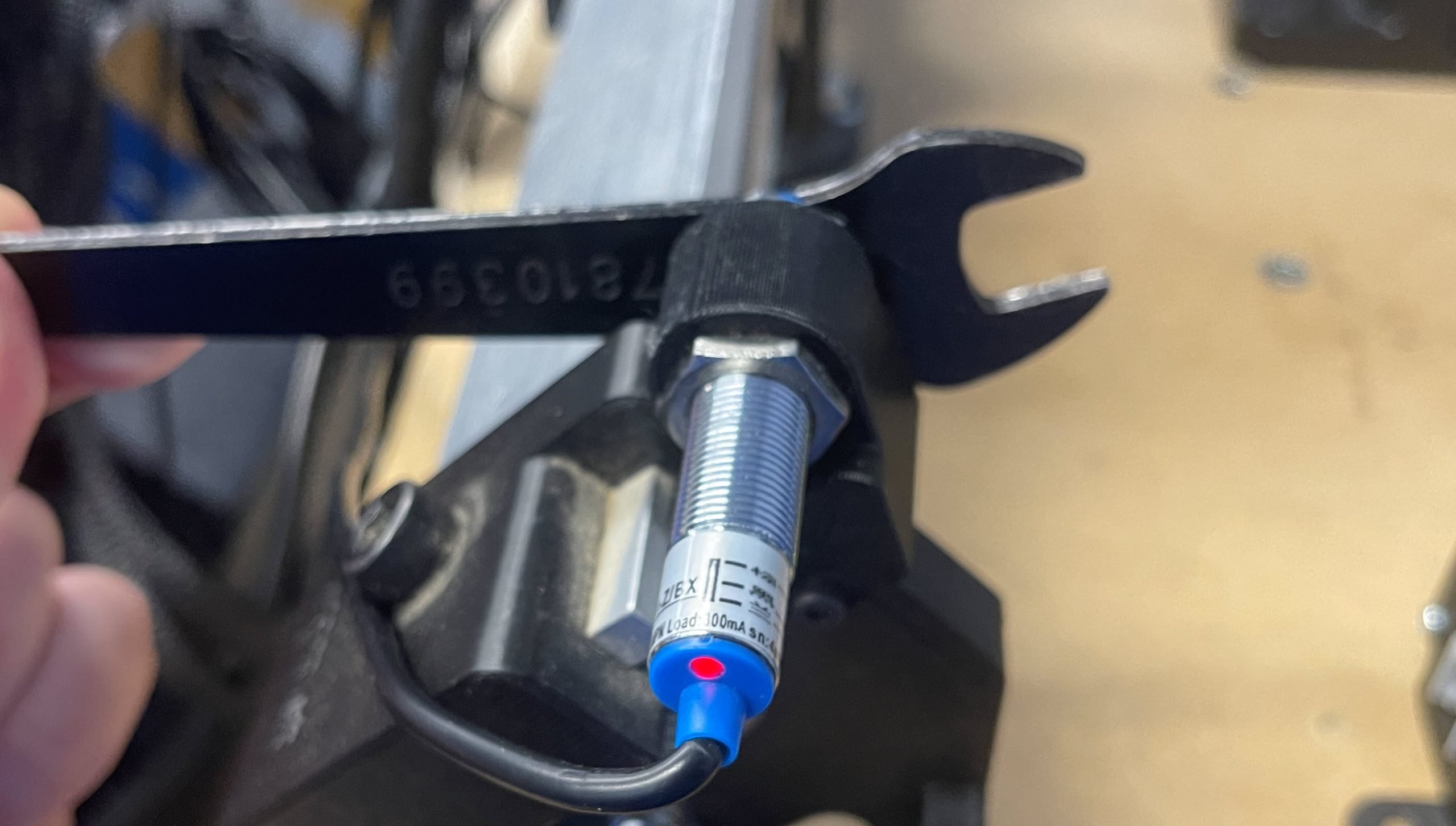
- Powered sensors – Place a metal object in front of each of the limit switches and look for the red light. This indicates that each sensor is plugged in correctly.
- Signal to the board – Navigate to your Machine Information icon on the main Carve tab to see if your board is receiving the signal from the limit switch, when the pins change from OFF to ON. Also double check that the correct axis is turning on.

Note: If you don’t see an axis turning ON/OFF, double check the connections on the board. We don’t use Y2 for example. -
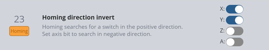
Turn Homing on – Navigate to the Config tab ➜ Homing/Limits section. Here you will see 8 toggles under the heading “Homing cycle”. There are many options for homing on the SLB, but just start by matching the toggles in the picture below (on, off – on, on – off, off – on, off). This will make the SLB home the same way that you’re already used to. Make sure to click “Apply New Settings”.
If you ever find you can’t unlock homing, homing isn’t setting the machine coordinates to zero, or other unusual behaviours, come back here to double-check this list since you might not have all the right settings turned on. If you’re still curious about the other options, check out the Homing & Limits Setup section.
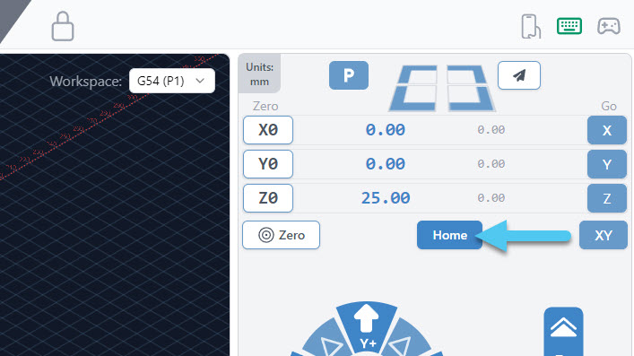
- Homing test – With things looking good on the firmware side, let’s run a homing cycle with gSender by pressing the ‘Home’ button on the main screen.
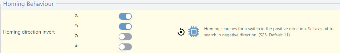
- Invert if needed – If you find any axes are reversed, return to the Homing/Limits section in the Config tab and flip any of the directions that are wrong. If you find that homing is behaving weirdly still, go back and check that you turned on the right toggles.
- Reduce homing speed if needed – If you’re finding your CNC gets stuck completing a homing cycle or is disconnecting, try reducing the homing “search seek rate” ($25) or increasing the “debounce delay” ($26) settings. Depending on your setup or sensors, the default values might be a bit too aggressive.
Classic gSender
- Powered sensors – Place a metal object in front of each of the limit switches and look for the red light. This indicates that each sensor is plugged in correctly.
- Signal to the board – Navigate to your Calibration Tool and check the Diagnostics tab to see if your board is receiving the signal from the limit switch, when the pins change from OFF to ON. Also double check that the correct axis is turning on.

Note: If you don’t see an axis turning ON/OFF, double check the connections on the board. We don’t use Y2 for example. -
Turn Homing on – Scroll down in gSender’s Firmware Tool to 22, also called “Homing cycle”. There are more options for homing on the SLB, but just start by matching the toggles in the picture below (on, off – on, on – off, off – on, off). This will make the SLB home the same way that you’re already used to. Make sure to click “Apply New Settings”.
If you ever find you can’t unlock homing, homing isn’t setting the machine coordinates to zero, or other unusual behaviours, come back here to double-check this list since you might not have all the right settings turned on. If you’re still curious about the other options, check out the Homing & Limits Setup section.
- Homing test – With things looking good on the firmware side, let’s run a homing cycle with gSender by pressing the ‘Home’ button on the main screen.
- Invert if needed – If you find any axes are reversed, return to 23 in the firmware tool and flip any of the directions that are wrong. If you find that homing is behaving weirdly still, go back and check that you turned on the right toggles for 22.
- Reduce homing speed if needed – If you’re finding your CNC gets stuck completing a homing cycle or is disconnecting, try reducing the homing “seek rate” (25) or increasing the “debounce delay” (26) settings. Depending on your setup or sensors, the default values might be a bit too aggressive.
LaserBeam Test
With your LaserBeam plugged into the SLB, let’s perform a quick test to make sure it fires up.
Current
- Turn on your LaserBeam driver. Go here if you want to refresh your memory on how to do this. If your driver doesn’t turn on, don’t necessarily attribute this to an issue with the board right away. First double check all these conditions are met since they are sometimes easy to forget.
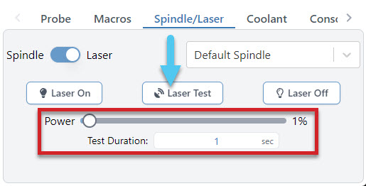
- In gSender, navigate to the Config tab ➜ Spindle/Laser tab in the Settings and toggle the spindle/laser controls on.
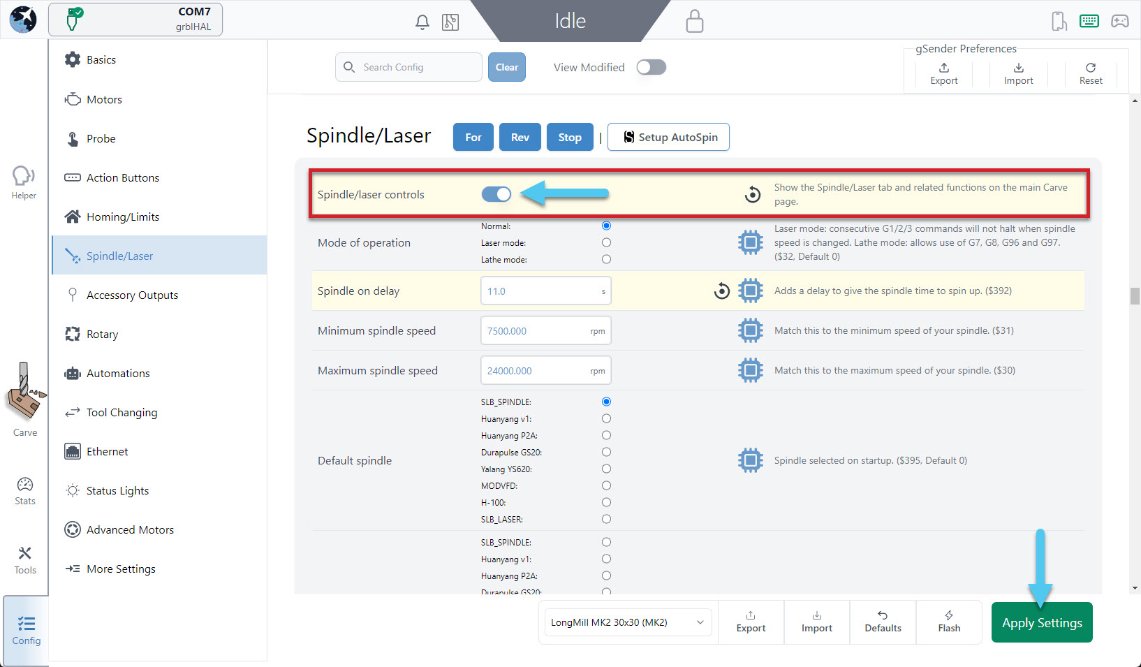
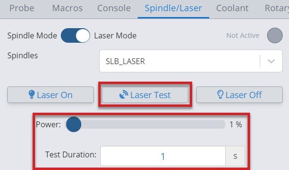
- Back on the main screen in the bottom right corner, navigate to the Spindle/Laser tab and select “SLB_LASER” in the dropdown list. After this, flip the toggle at the top to ‘Laser’.

Note: Ensure that you are wearing your safety glasses! - Ensure your power is set to 1% and your ‘Test Duration’ to one second. Now when you hit the ‘Laser Test’ button your diode should momentarily emit a faint beam. This means that the SLB is controlling your laser successfully!
Classic gSender
- Turn on your LaserBeam driver. Go here if you want to refresh your memory on how to do this. If your driver doesn’t turn on, don’t necessarily attribute this to an issue with the board right away. First double check all these conditions are met since they are sometimes easy to forget.
- In gSender, navigate to the Spindle/Laser tab in the Settings and toggle it on.
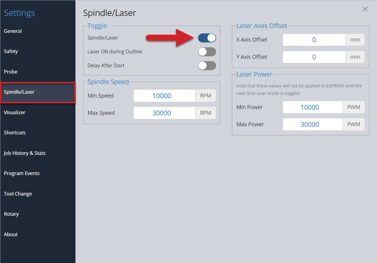
- Back on the main screen in the bottom right corner, navigate to the Spindle/Laser tab and select “SLB_LASER” in the dropdown list. After this, flip the toggle at the top to ‘Laser Mode’.

Note: Ensure that you are wearing your safety glasses! - Ensure your power is set to 1% and your ‘Test Duration’ to one second. Now when you hit the ‘Laser Test’ button your diode should momentarily emit a faint beam. This means that the SLB is controlling your laser successfully!
If the laser testing didn’t go as planned, check your wiring and that you’ve turned on your driver correctly. If you go back through the steps still with no success, you can always read more about laser setup on our more advanced SLB Manual page.
Rotary Test
One thing worth double-checking is that you’re getting the correct amount of movement out of your rotary axis. You can do this by simply jogging the A-axis by 360 degrees to see if it makes one full rotation.
If this doesn’t happen, then your steps/mm machine setting might be set incorrectly. You can find this in the Config tab or Firmware tool under “A-axis travel resolution” also known as $103, and for the Vortex rotary this value should be 79.01234568. If you’re not using the Vortex, then there’s some other troubleshooting here.
Routing
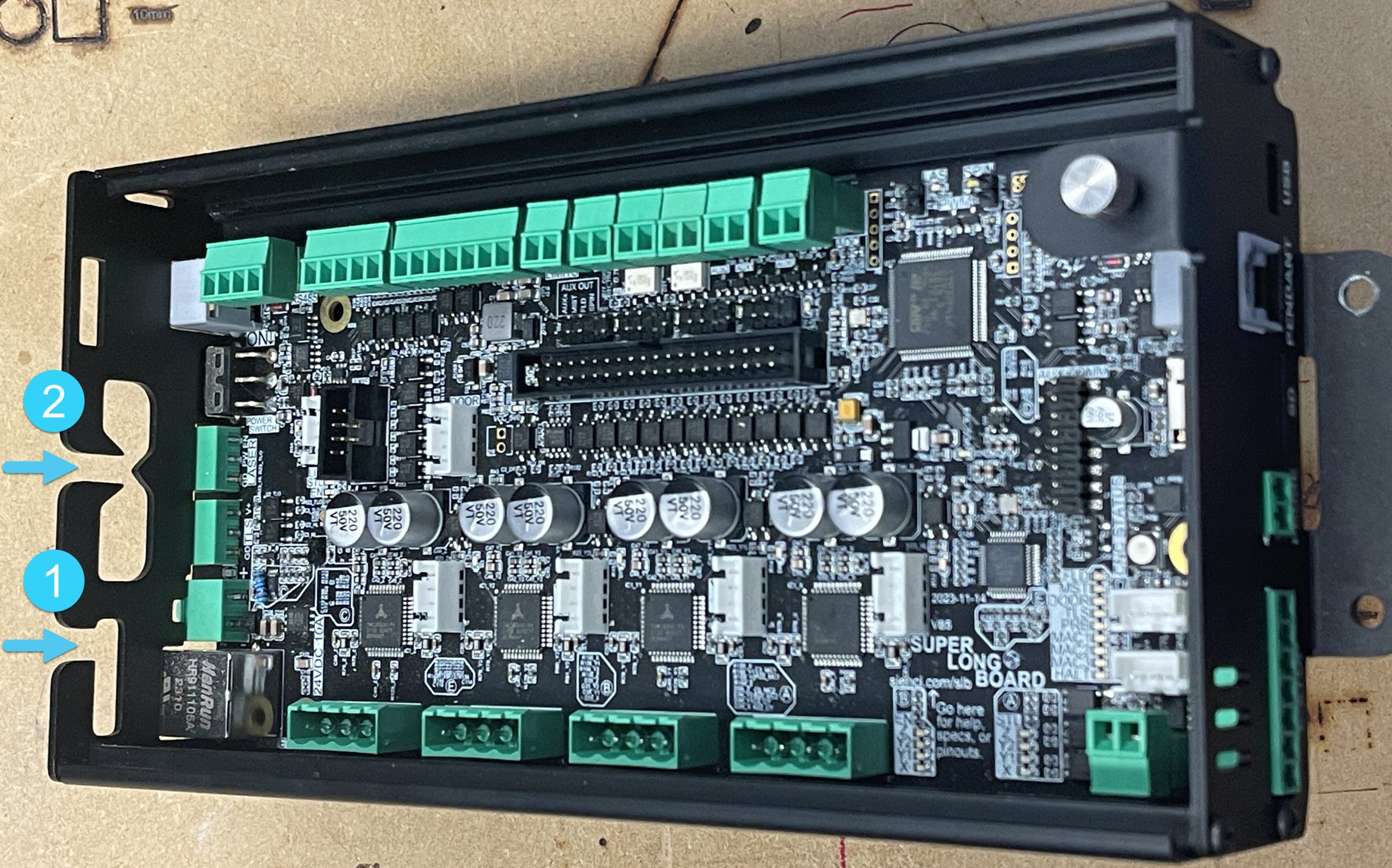
The SLB enclosure has wire management built-in to keep all your wires in place if you ever need to open the cover and look at the inside. Use these by routing all the wires inside the enclosure through the two cable guides at the Back.
- The smaller, #1 enclosure is meant to fit all 4 motor cables snugly
- The larger #2 opening should fit all wires other than the motor cables
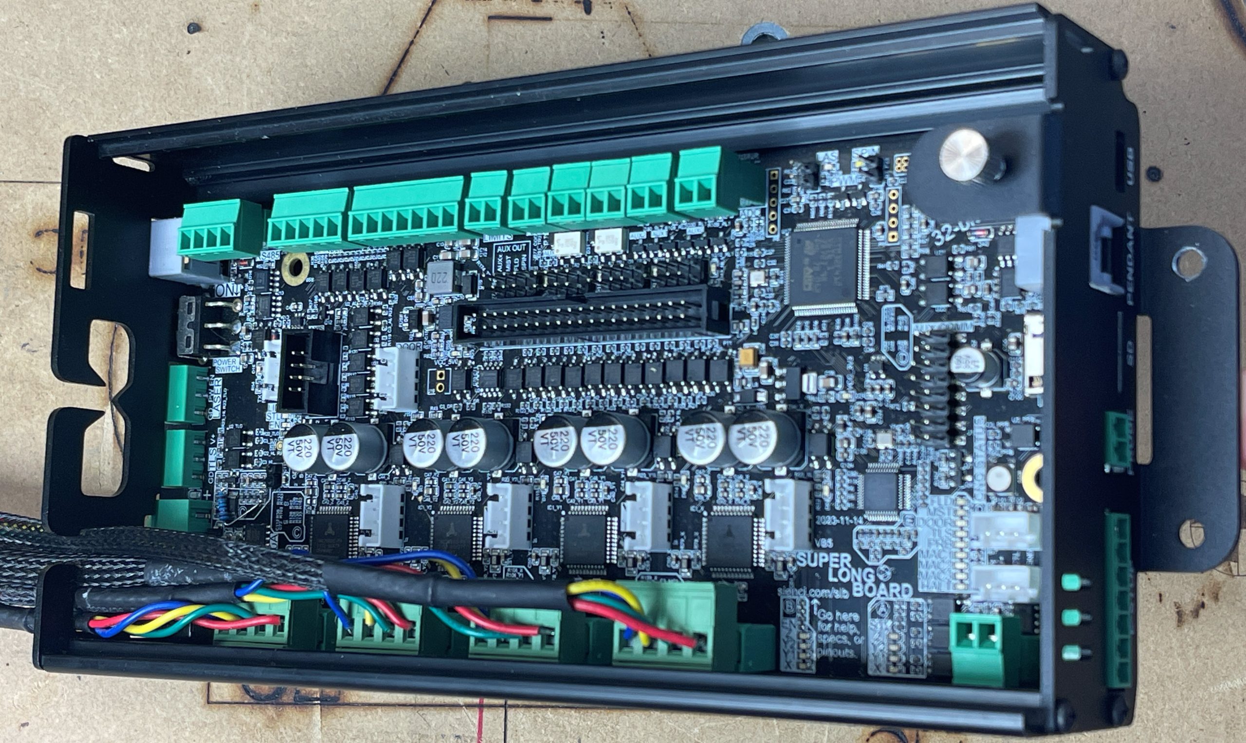
Here you can see all of the motor cables are routed.
Once all of your cables are routed correctly out the back of the board, you can put the cover back in place. Simply tilt the cover back into the slot on the bottom of the case, ensuring the keyhole is over the screw, then slide the cover to the left
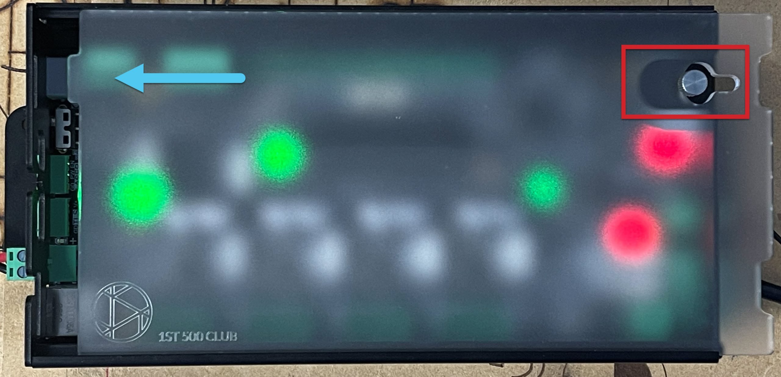
Once the cover is in place, turn the thumbscrew clockwise until finger tight. If you notice a small gap between the cover and the back of the case, this is by design to ensure that the cover maintains a tight fit over time.
Mounting
You can mount your SLB however you like. Some factors to consider might be your machine setup, computer location, if you have an enclosure, or if you want to access other things or see the pretty lights on the board. The most versatile way is the 4 holes in the SLBs enclosure which will allow you to mount it to any flat surface, but if you have a LongMill MK2 you also have the option to mount it directly to your Y-axis rail (not compatible with MK1).
Some of the extra tools you may need for this step:
- Bolting to MK2 Rail – M5 Allen wrench, plus grab the hardware and bracket provided with the SLB
- Screw Down / Flat Mounting – 2 to 4 wood screws (minimum size #4 or ¾” and min length of ½”) plus the necessary screwdriver or bit driver
Bolt to Rail
For rail mounting, slide the two T-nuts onto the track above the left Y-rail and loosely thread on the two M5 bolts. You may need to remove your limit switch on MK2’s temporarily to enable the nuts to be slid into the rail.
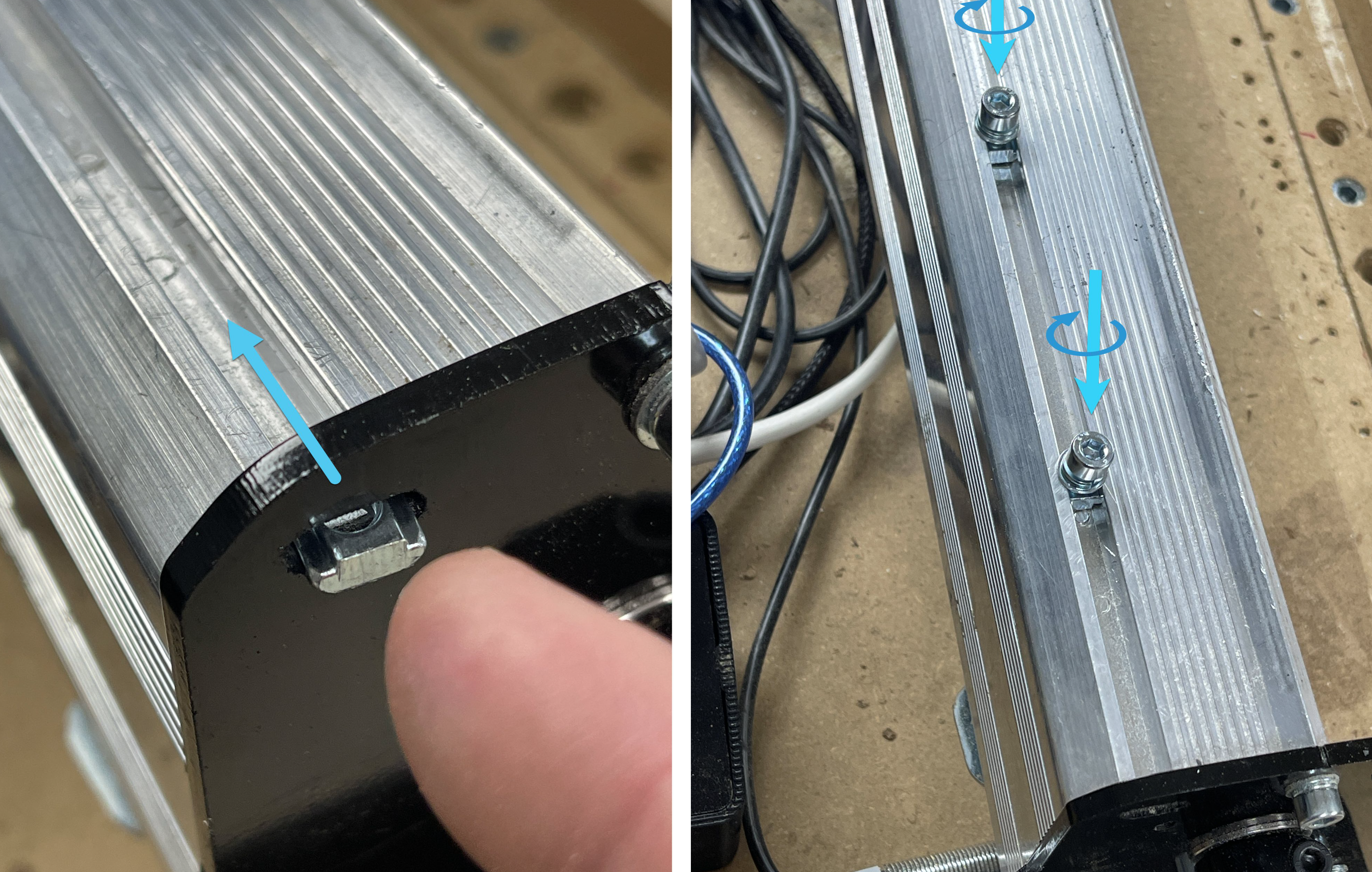
Insert the sheet metal bracket into the slot at the back of the SLB enclosure. The bracket will feel loose for now so you’ll want to hold it in place until the next step.
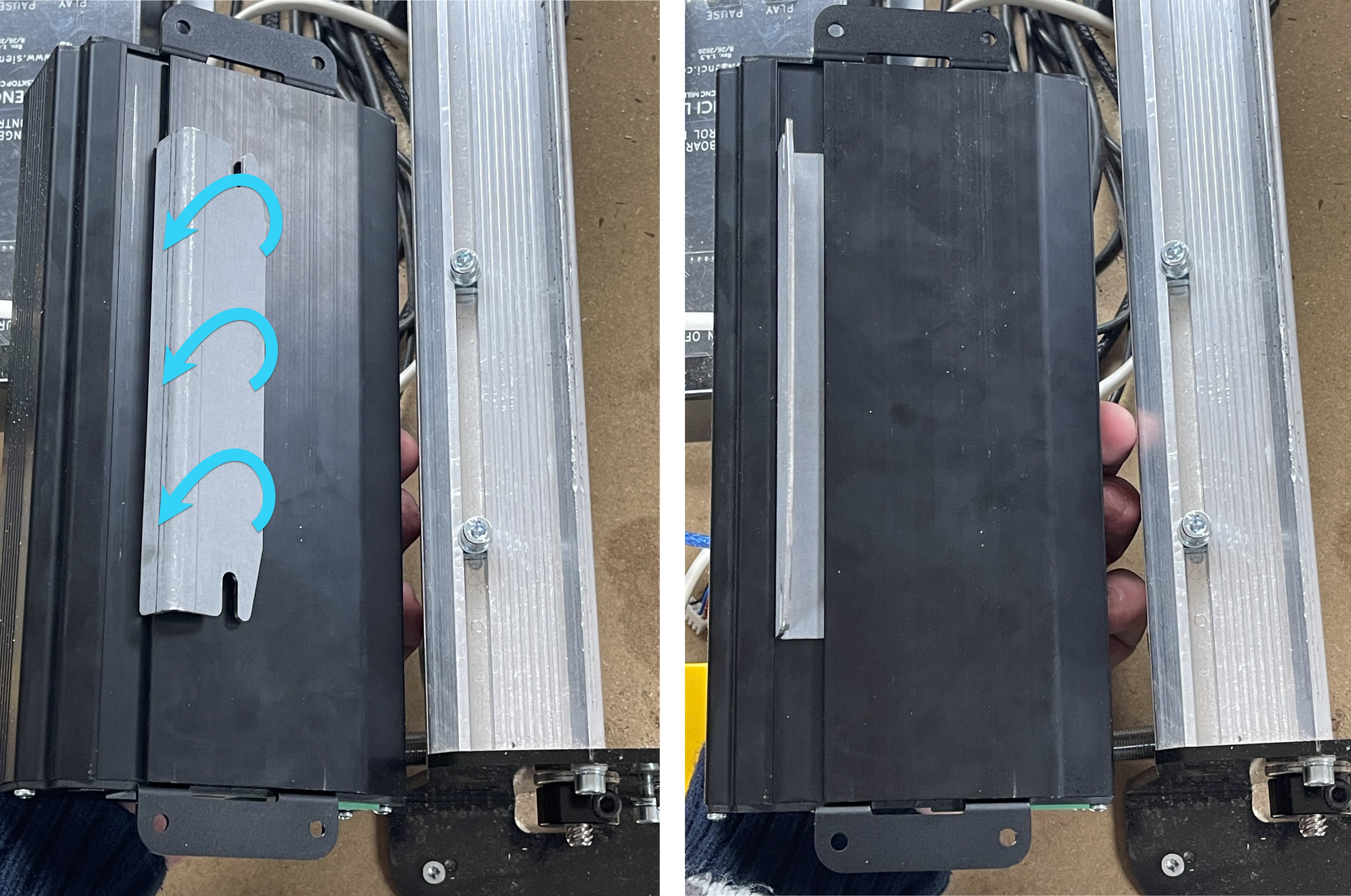
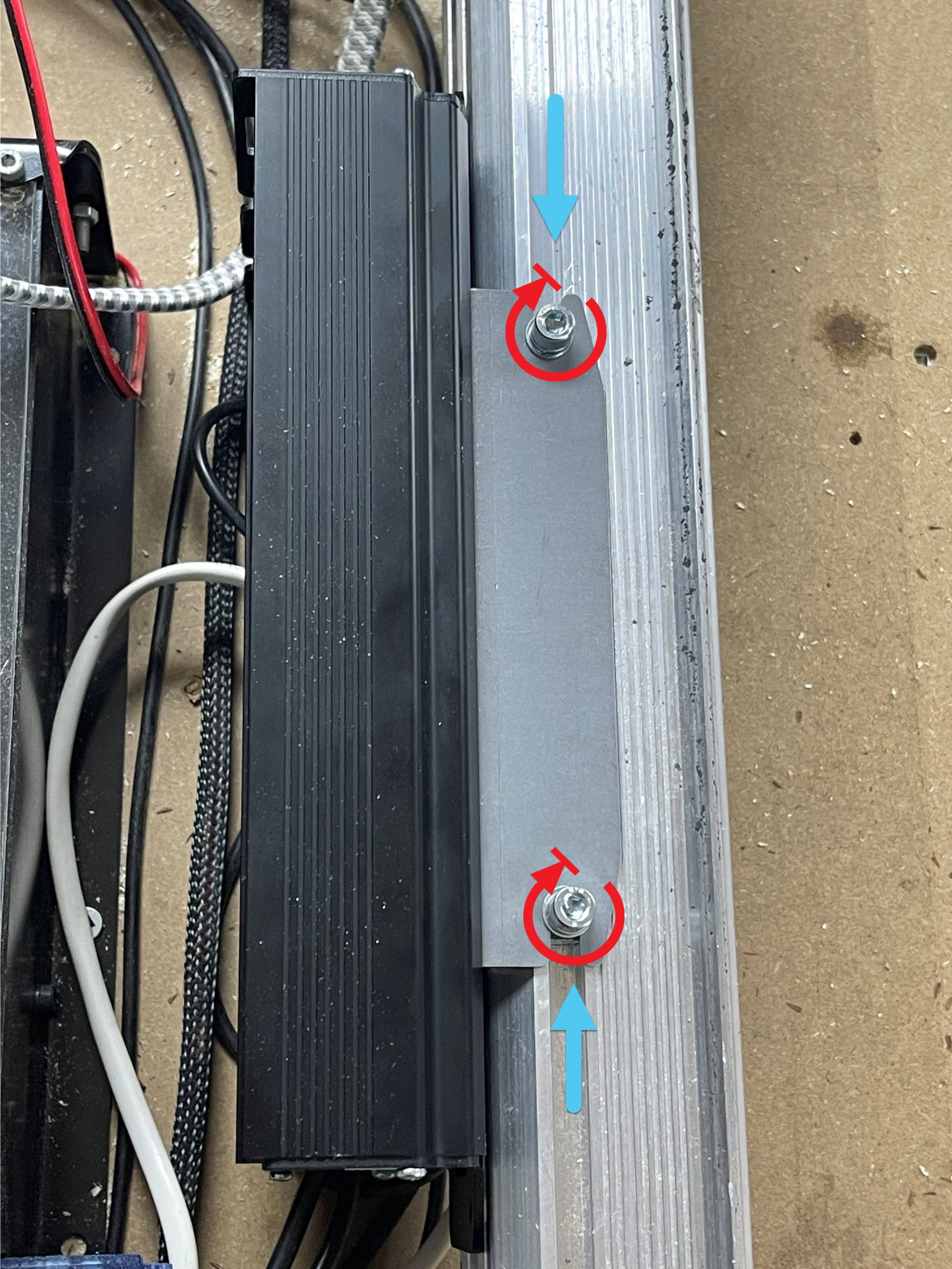
Place the bracket-enclosure assembly onto the Y-rail and slide the two screws into the slots in the bracket, then tighten the two screws with an Allen key to lock the entire assembly onto the rail.
Screw Down
You can mount your SLB flat on your wasteboard next to your machine, or even on the side or at the back of your workstation. You can also hang the SLB vertically. The enclosure has been designed with reasonable consideration for dust penetration and vibration, but if you are a more cautious person you can feel free to mount the box further away from your CNC.
When placing your SLB on its own or among other CNC control electronics, consider that most wires are designed to route out the backside of the enclosure with the exception of a handful of more typically accessible plugs on its front like the E-stop and USB.
It’s easy to use the enclosure as a template to mark and drill the holes. The holes are 4.5mm large, spaced 45mm from each other and 230mm from the opposite pair. They’re not perfectly centered on the box but close to it.
You can use whatever bolt or screw type you like but the easiest approach is to use a minimum of 2 countersunk wood screws on diagonal holes from size #4-#8 and a minimum length of ½”. You might have to remove some of the plugs on the ends to access the holes when you screw down the enclosure.
Congrats!!! You have successfully completed all the general assembly and setup to get your SuperLongBoard up and running.
Time to Smell the Roses
This section on ‘Upgrading to the SLB’ was written to cover all the necessities that the SLB has to offer by default, so you should now find that your machine can:
- Run more reliably
- Cut, jog, and home faster
- Run more quietly at many speeds
- Safer E-stop that de-powers motor and disables accessories
- Probe more quickly and easily off touch plates
- Perform faster and smoother laser engraving
This covers a lot of the important stuff that likely drew many of you towards picking up the SLB! If you weren’t planning to do anything more complicated with your SLB yet, then we’d recommend that you stop here for now so you can enjoy all the new perks.
That said, the SLB is still capable of plenty more if you were planning to dive into a bit more complexity with wiring and firmware configuration. These are all covered on the SLB Manual page, such as:
- Ethernet Hookup
- LED Strips
- More help for Laser setups
- Using the Action Buttons on the E-stop
- Other Accessory Outputs
- Setting up Spindle/RS485
- Tool Length Sensor
- Fully independent rotary 4th axis
New Behaviours to Expect
There will be some new behaviours to expect from your SLB compared to the way you’re likely used to your previous board behaving. Take your time to understand them and before you know it they’ll become normal too!
- For now, the SLB will continue working the best with any typical ‘grbl’ post processor setup. If you already had a working grbl setup then you won’t need to change anything.
- Whenever you press the E-stop, expect an ‘Alarm 10’ to appear. This shows that the board saw your E-stop press and will shut down the motors and all other accessories. Once you untwist the E-stop (the light will come back on), you’ll be able to unlock the machine and continue what you were doing. The E-stop will cancel any currently active job, so if you want to resume you’ll want to re-probe or re-home and then use ‘Start from Line’ to resume the job back where you left off.
- The yellow ‘processing’ lines in the gSender visualizer might extend out further when you’re running a job, this is just because the SLB can store more future movements in its memory than other boards
- Swapping between the Spindle/Laser is a bit more involved, the SLB Manual page goes into it a bit more on it. Because of this, we’d recommend that you set up your SLB for whatever Spindle/Laser output you’d tend to use as your default, so that you can just power on your machine and not have to worry about many other steps after that
- There will always show the ‘Unlock’ button in gSender. This is because there might be some times where if your SLB gets stuck, you can use the ‘Unlock’ button to help recover it.
- This should never change after your first setup, but you’ll need to make sure that from now on you always connect to gSender or other g-code senders with ‘grblHAL’ being the selected firmware.
- Some settings in gSender aren’t used anymore since the SLB stores them itself. This includes the Spindle/Laser settings for spindle min/max speed, laser min/max power, and laser axes offset, as well as all the Rotary settings except for the Rotary toggle.
- Looking at the Config tab or Firmware Tool
- There are now a lot more settings and categories, but if you’re not using any advanced features then you can ignore them
- Some of the new settings can only fully apply once you’ve powered off and back on the SLB
- The process for flashing grblHAL will now require that you get the most up-to-date firmware version for your SLB; the firmware and the process for flashing can both be found on the SLB Manual page
Troubleshooting
If you are still running into any issues with your new SLB, please see the Troubleshooting Section on our more Detailed page. You can also always contact us directly at support@sienci.com.