
This page covers all the advanced features of gSender such as shortcuts, macros, workspaces, calibration tools, controlling spindles, rotary axes, lasers, coolant, and more. Remember, you can always quickly navigate the page by clicking the headings in the ‘Page Contents’.
gSender Customizations
Listing off a few more customizations before moving on to new features, some which were already mentioned on the Setup & Layout page, we’d encourage you to look into these options to personalize your gSender experience (you can find them all in the Config tab):
- Reconnect automatically
- Will connect to your last CNC anytime you boot up your computer or open gSender and the CNC is still plugged in.
- Visualizer theme and Dark mode
- In the Basics section, both these settings help change the colours in gSender based on what will be easier on your eyes. Check them out if that sounds interesting!
- Lightweight mode
- This mode enables gSender to run faster on computers that are older or less powerful by turning off processor-heavy aspects of the visualizer. It comes in two flavours, either it’ll show your file as a picture with no 3D movement, or it’ll turn visualization off completely. You can toggle it on/off using the Feather button on the left side of the visualizer on the Carve page.
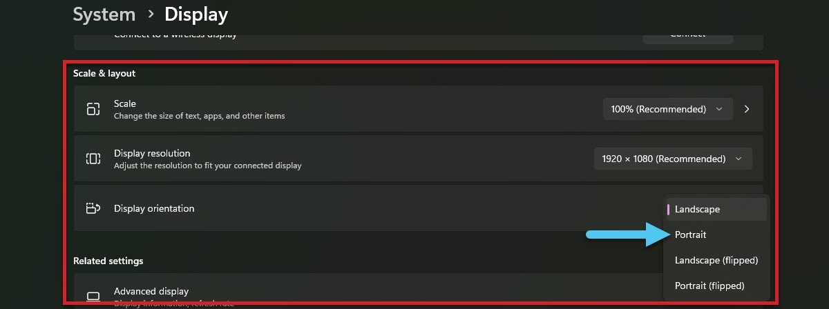
- Portrait layout
- gSender takes on a whole new life if you prefer to use your monitor in portrait mode, and we actually prefer using it in portrait on touchscreens. If you’re interested in trying this out it should just be a setting in your operating system, and gSender will adapt automatically.
- gSender takes on a whole new life if you prefer to use your monitor in portrait mode, and we actually prefer using it in portrait on touchscreens. If you’re interested in trying this out it should just be a setting in your operating system, and gSender will adapt automatically.
- Jogging presets
- You can set these based on the size of your CNC or to match how you like to move your machine around to make jogging around feel more natural.
- Notifications
- In Basics ➜ Notifications, these can be customized to give you warnings when you load bad files, provide information at the end of a job, and more.
- Enable other CNC functions
- If your CNC supports them, this can include a Spindle, Laser, Rotary axis, and more. Just go to the appropriate section in Config and the first option you should see should mention “enabling” it. After Applying the changes you’ll see a new tab appear in the bottom-right of the main Carve screen.
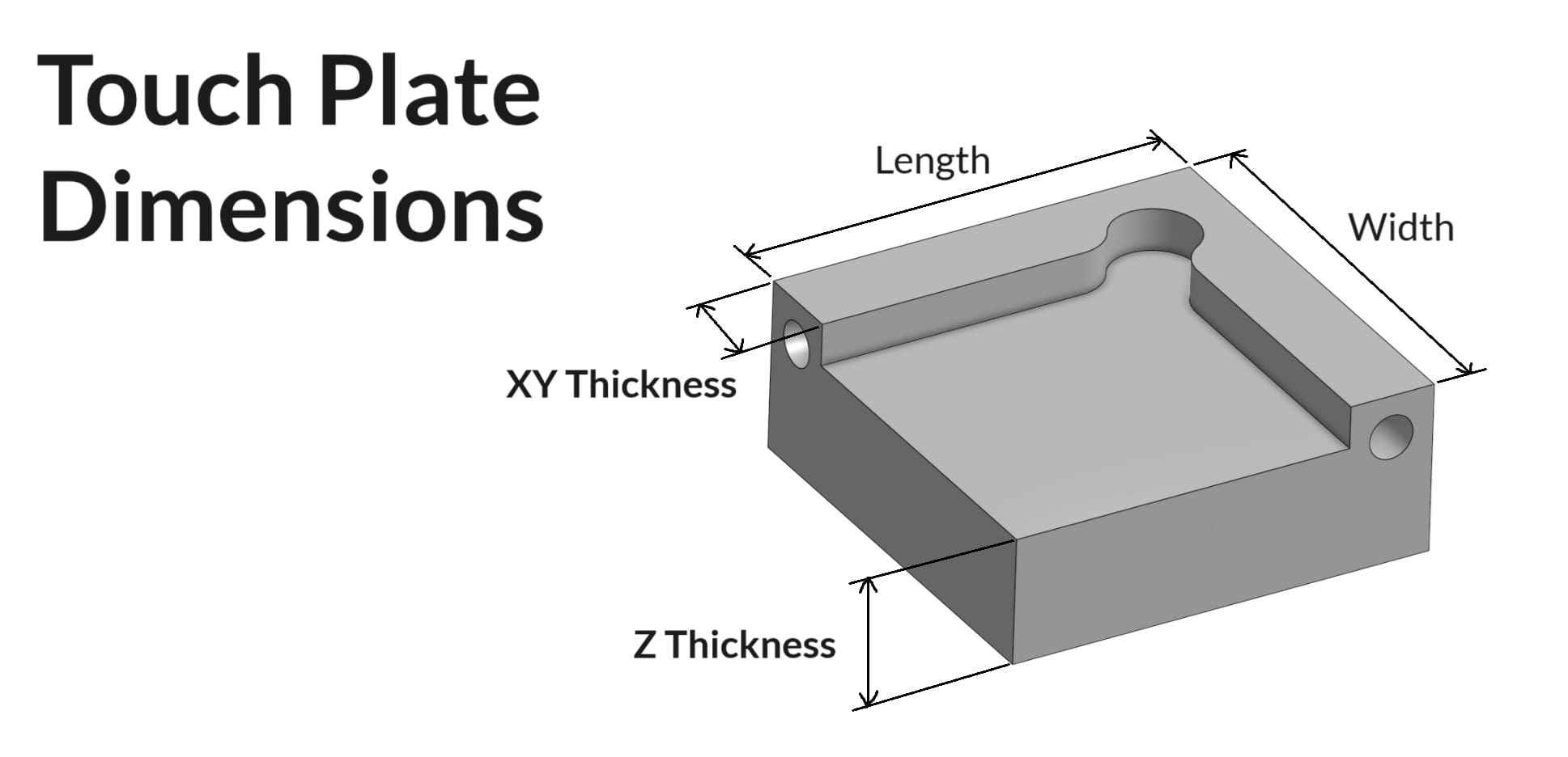
Touch Plate Setup
gSender has support for three types of touch plates:
- The Standard Block design
- Z Probe, also sometimes referred to as a ‘puck’
- And our specialized AutoZero touch plate
If you’re trying to set up a custom Standard Block plate, use some calipers to make the measurements shown below. Once these are noted down, enter these into gSender’s ‘Probe’ settings in similarly named entries, apply the changes, and now you should find that gSender’s probing routine has been altered to fit the shape of your touch plate.
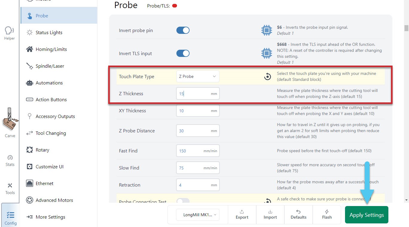
For a custom Z Probe, setting up is simple since you just need the thickness of the ‘puck’. Enter that value into gSender’s ‘Probe’ settings under ‘Z Thickness’, apply the changes, and you should be good to go!
The AutoZero touch plate doesn’t require any setup at all, other than selecting it, and applying the changes!
Shortcuts
Starting off as a more advanced gSender user, the first feature you’ll want to leverage is shortcuts. These can allow you to assign gSender shortcuts or CNC actions to keyboard keys or even to gamepads and joystick movements – very useful for things like jogging, setting zero, running macros, and menu navigation.
You can access and set up shortcuts by clicking the keyboard or gamepad icons in the top, right corner. Any changes you make in these windows will save automatically, and setting up a shortcut is as easy as finding what action you want to perform and what button you want to activate it. Also, for easy reference, the keyboard and gamepad icons can be clicked from anywhere in the app and will light up green if they detect you have a keyboard or gamepad connected to your computer.
Going to the ‘Tools’ tab on the left side of the window is another way to access the Keyboard Shortcuts or Gamepad. 3rd party apps like JoyToKey, Xpadder, Comfort Keys Pro and reWASD also allow you to do this, but to eliminate needing to download and configure other programs we’ve rolled all the functionality into gSender itself.
Keyboard Shortcuts
Either for use on a keyboard, macro pad, or mini Bluetooth keyboard, these are split up into categories so they’re easy to locate and modify. There are over 70 shortcuts with presets already available for carving, overrides, jogging, zero setting, probing, macros, visualization, window navigation, and more!
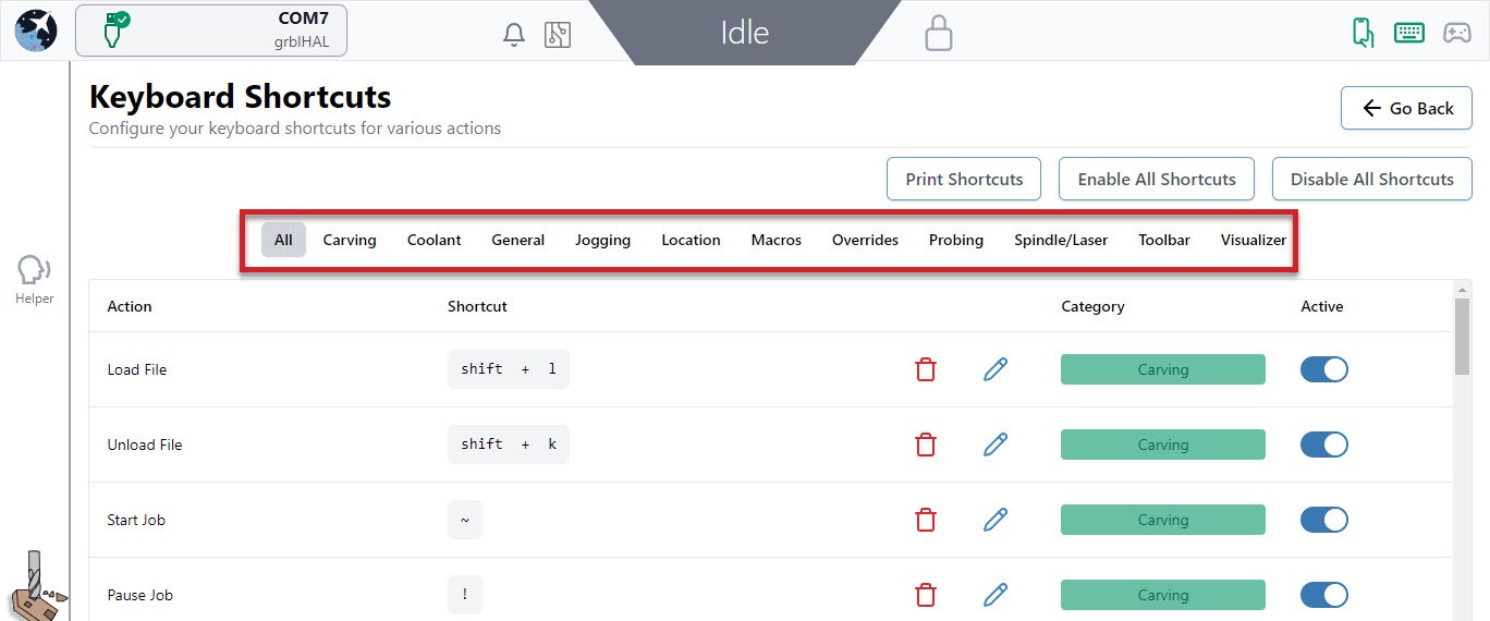
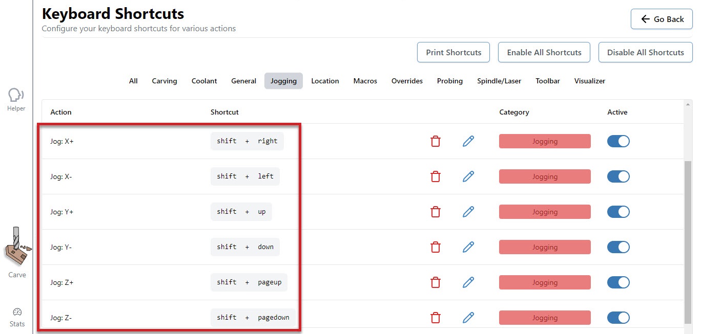
Common Shortcuts
A great place to start is the Jogging category. In the picture below, see that right now we can jog the X-axis by hitting the shift + right or shift + left keys. The Y-axis responds to shift + up and shift + down keys and the Z-axis uses the shift + pageup and shift + pagedown keys. Being able to look at your CNC, while your hand is on your keyboard is a great way to ensure you are moving in the right direction, without having to look back at your screen to click the mouse on the right button.
You can use the preset shortcuts, edit them, and/or add your own. Click the pencil to the right of each shortcut text box to bring up a popup window that allows you to add or edit your own key combination (shown in the example below). It’s as easy as pressing the key or key combination. You’ll also be informed if the combination you’ve entered is already used elsewhere and be given the option to overwrite the existing one if you want.
You can temporarily turn off specific shortcuts or disable all of them if you’re worried about mistakenly activating them by using the toggles in the ‘Active‘ column, clicking the ‘Disable All Shortcuts‘ button, or using the shortcut called ‘Toggle on/off shortcuts’.
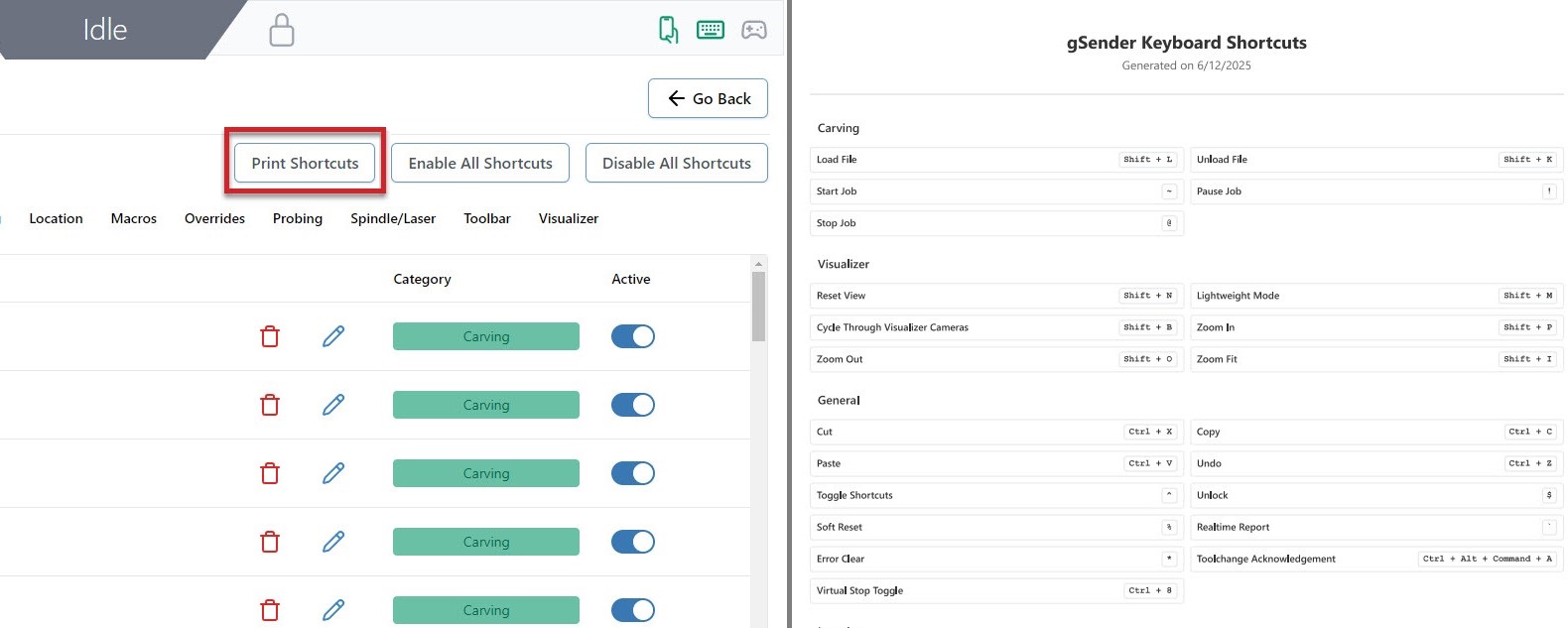
Shortcut Printing
Find yourself forgetting how you’ve configured your keyboard or gamepad profile shortcuts? Hit the ‘Print‘ button to generate a simple PDF that you can store on a tablet or print on some paper to keep next to your CNC. This PDF will contain all the shortcuts you’ve created and what actions they’re assigned to.
Gamepad Shortcuts
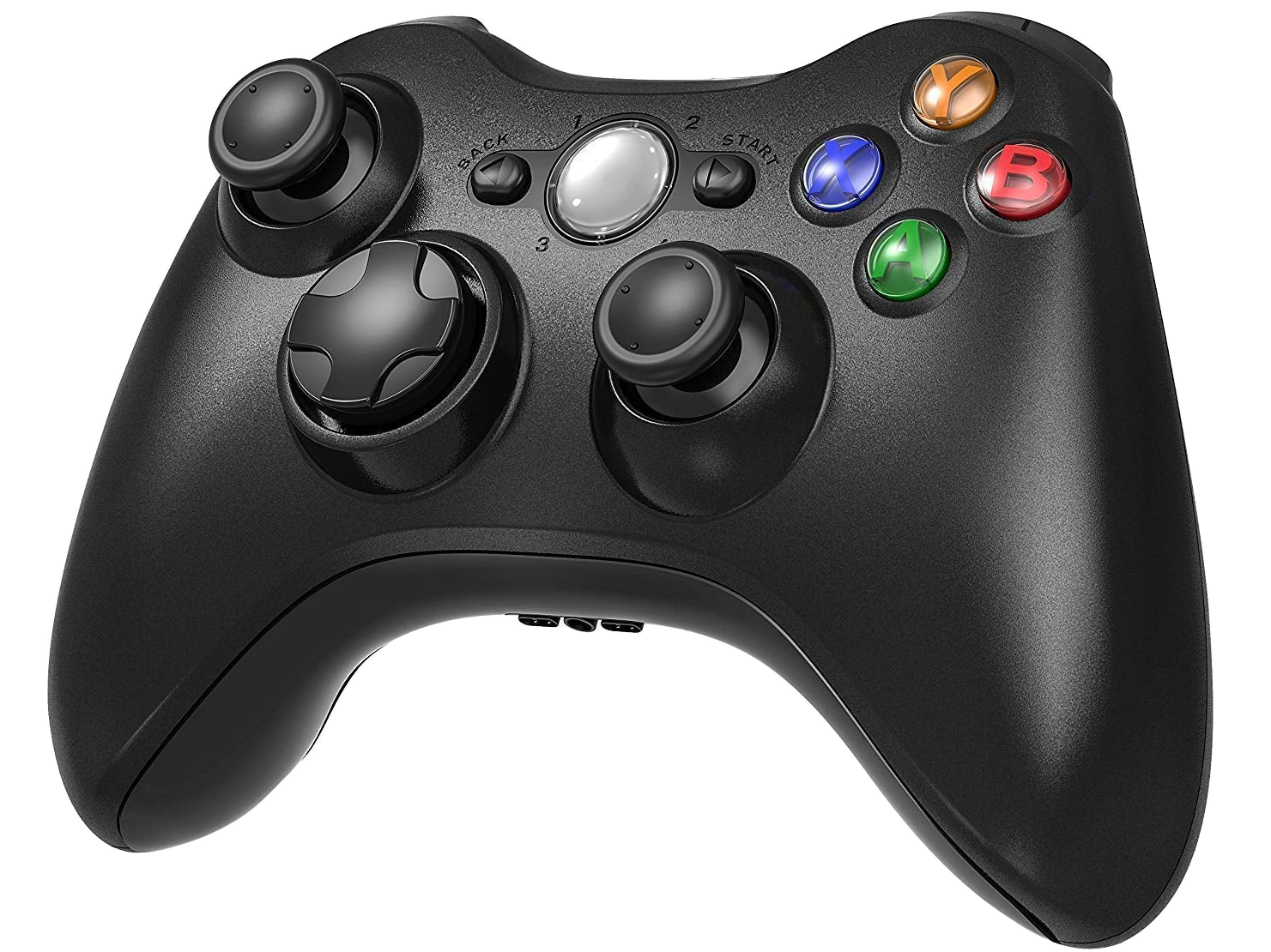
Many users really love this feature since using a controller is convenient (especially for when you’re closer to your machine), inexpensive, and makes certain repetitive actions much easier. Common options are Xbox, PlayStation, and other third-party controllers available to buy online.
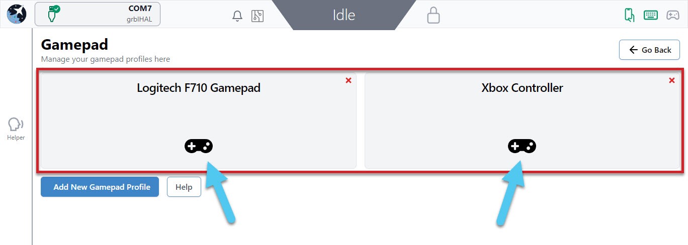
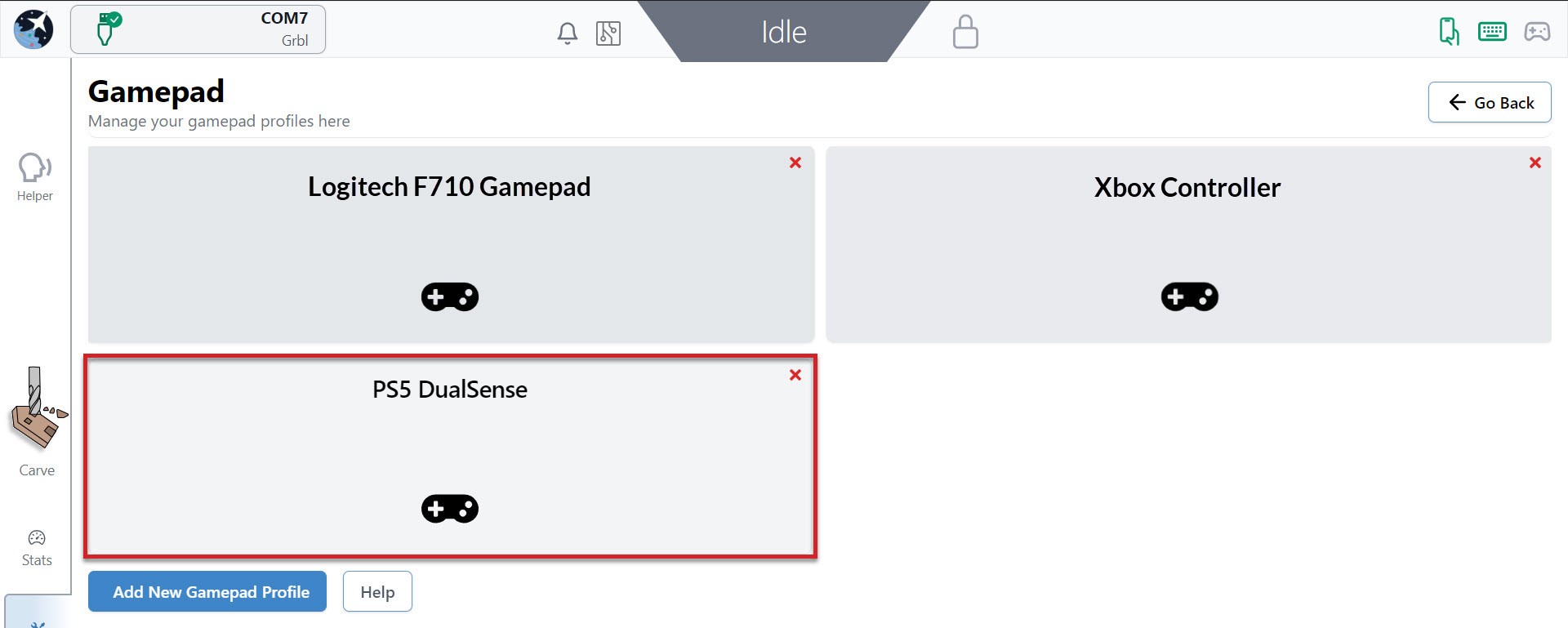
We have some pre-made profiles for gamepads we’ve already tested with gSender and you can still reference these if you have a different gamepad or want to make your own.
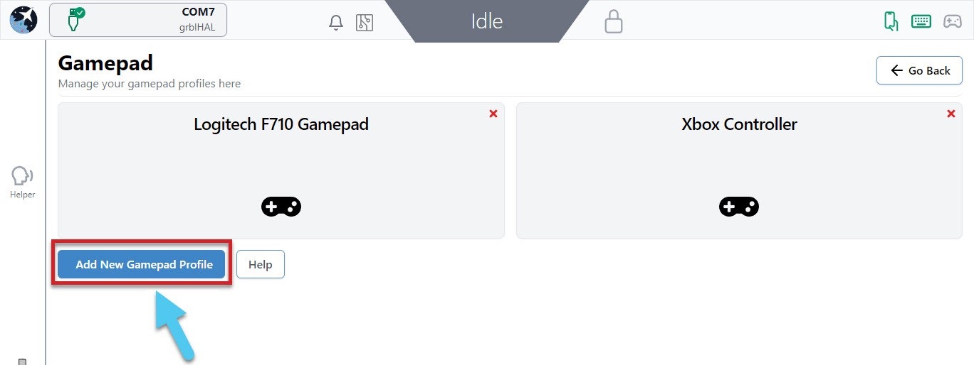
To create your own profile, connect your gamepad to your computer and click the ‘Add New Gamepad Profile’ button, then make sure the gamepad is recognized before beginning to assign actions to each button. Creating different profiles mean you can set up multiple gamepads if you’d like since they each have their own unique ID.
If you run into difficulty with getting a particular gamepad set up in gSender, consider:
- Some gamepads may require drivers to be downloaded so your computer can read the signals that the gamepad sends out.
- Go into the gamepad profile while it’s connected and click the Help button where you’ll be able to diagnose whether your gamepad is broken and sending out bad signals.
- Searching for documentation provided by the manufacturer (for example, Xbox or PlayStation).
Tested Gamepads
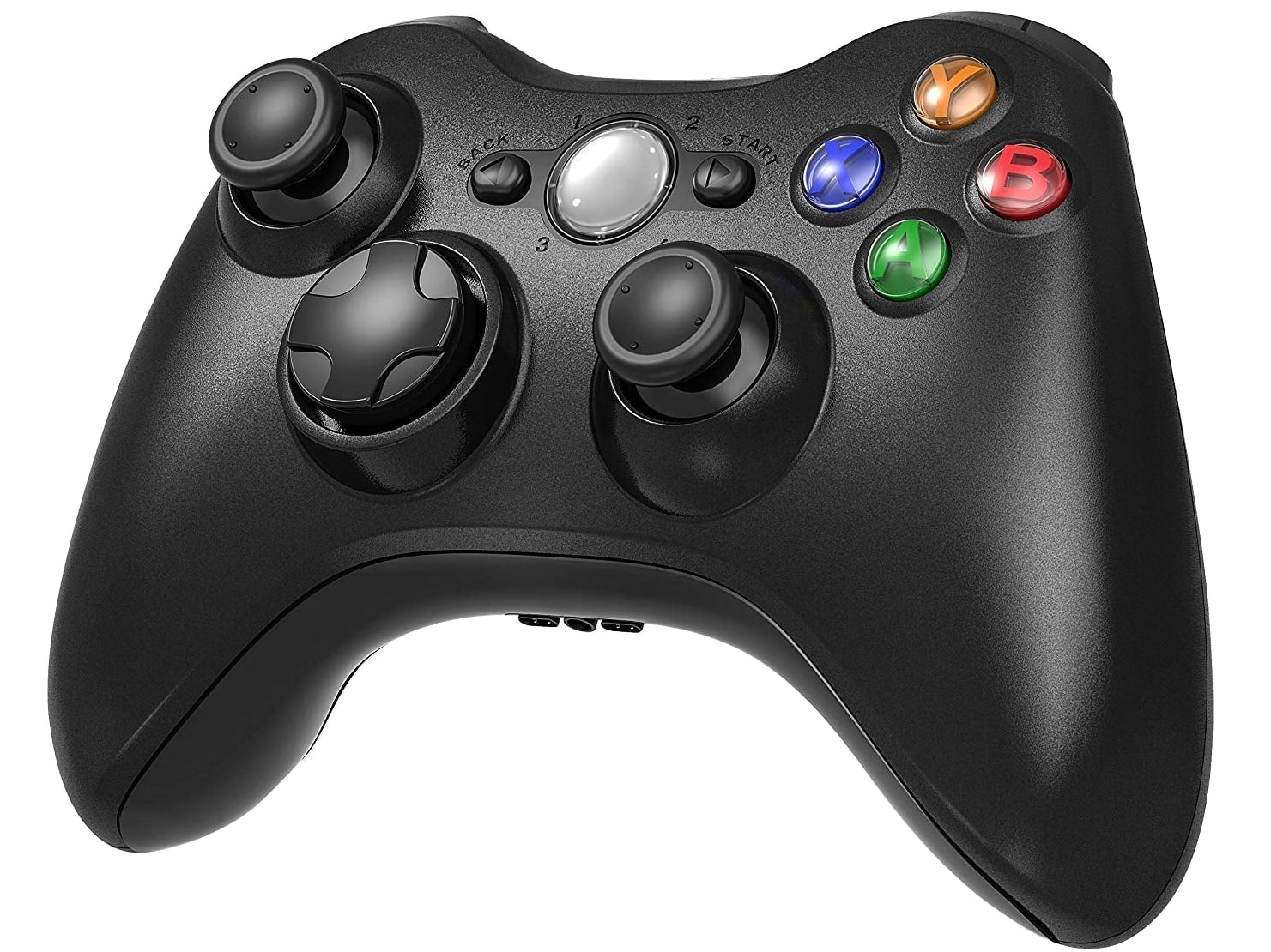
To better guarantee your experience using a gamepad in gSender, we’ve taken the time to test a shortlist of some common and affordable options that are easy to source. With community help, we hope to continue growing this list of officially tested gamepads which currently includes:
 |
YCCTeam Xbox Controller
|
 |
Logitech F710
|
Having a listed gamepad means you can both be more confident that your hardware will be compatible with gSender, as well as many of the ‘tested gamepads’ will have pre-made shortcut profiles built right in to save you time setting up your own.
Gamepad Setup
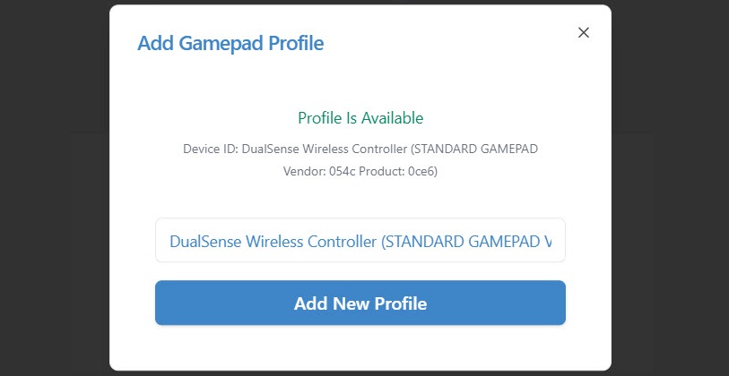
Hit the Add New Gamepad Profile button, connect your controller to your PC and press any button on it. gSender will identify and provide a profile if one is available. You can see in the screenshot below, it correctly identifies the DualSense Wireless Controller. If no profile is already tied to the controller, enter your profile name and hit Add New Profile.
Once you have a profile for your connected gamepad, click on that profile to edit it.
Inside a profile, you’ll be able to see if that specific gamepad is currently connected and be able to assign shortcuts to the two major groups: buttons, and thumbsticks.
Buttons are the most versatile in how they can be set up. Any button on your gamepad can be set up to:
- Activate an action
- You can assign a button as a ‘Second Action Button’ which acts similar to a ‘Shift’ key on your keyboard to allow you to create two-button combinations on your gamepad.
- You can also assign a ‘Lockout Button’ which acts as a safety lock for your CNC when controlling it with the gamepad. If you set up a lockout button, then no other buttons on the gamepad will work until you’re pressing on the lockout button. This stops from pressing buttons accidentally or if you dropped your gamepad on the ground.
To add an action to a button, start by pressing the button on your gamepad to see which one on the list lights up green. In this case, the X button lit up button 0. After pressing the + symbol in the Action column, you will see a list of actions you can map to that button. In this case an action was added for Rapid Position – Back left corner, so now when the X button is hit on the gamepad, gSender will move the CNC to the back left corner!
You can repeat these steps to keep adding more shortcuts to your gamepad, this also includes:
- If you’re having difficulty remembering your gamepad buttons, you can click on the black box label and rename it to whatever you’d like.
- The ‘2nd Action’ column will allow you to give each gamepad button a second shortcut action once you set up a ‘Second Action Button’. Do this by clicking the
+symbol in the Action column of the button you want to use, then clicking the ‘Use as Second Action Button’ toggle on the right side. - Assign a ‘Lockout Button’ in a similar way but by toggling the ‘Use as Lockout Button’ toggle on the right side.
Thumbsticks are set up to be used for jogging because of the ability to move them a little or a lot, which is different from buttons which can only be clicked on or off. This works well because most gamepads tend to have 2 thumbsticks (like the Xbox controller shown above), meaning you can use one to jog in the X and Y, and the other to jog in the Z and A (if your machine has a rotary axis). For gamepads that don’t have thumbsticks this is still fine because buttons can also be set up to jog.
On the right side of the gamepad profile window, you can see the options for what axis you’d like to move with your gamepad thumbsticks. Similar to setting up buttons, you can move the thumbstick to see which one lights up, and you can also assign a ‘2nd action’ if you’d like. In this example, Stick 1 controls the X-axis left and right, and the Y-axis forward and back while Stick 2 controls the A-axis with left/right and the Z-axis with up/down.
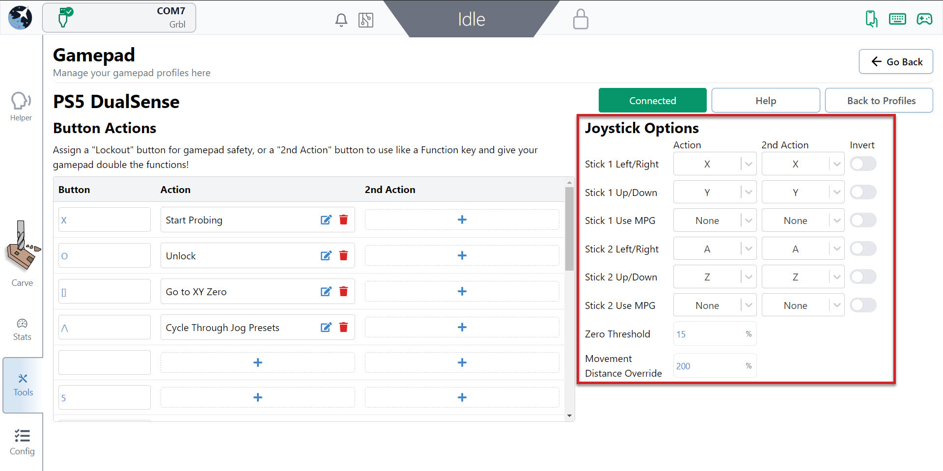
Once you’ve set up your thumbsticks, you’ll find you can push them any amount and the distance you push them will decide the speed that axis moves at. If you’ve set up both the left/right and up/down, you can also mix these to make continuous diagonal movements to get to your final location easier. You can also flick the thumbstick once and the CNC will move one increment, according to the rapid/normal/precise movements you have set up for Jog Controls.
- If you find your thumbstick is moving the axis in the wrong direction, use the ‘Invert‘ checkbox to correct that
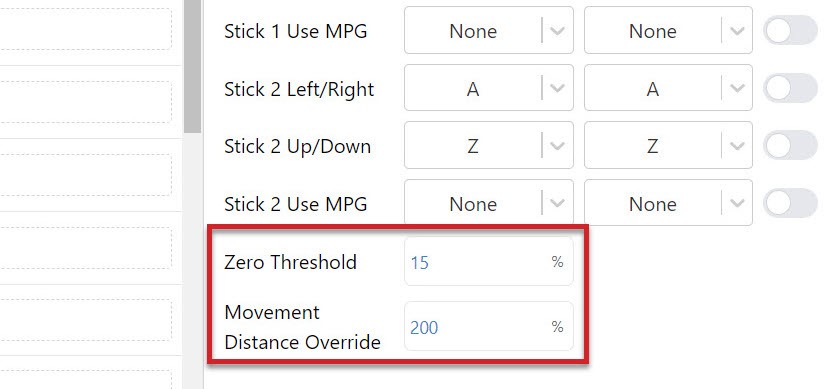
- If you let go of the thumbstick and the axis keeps moving, increase the ‘Zero Threshold‘ amount since your gamepad might be older and more worn out
- If you get jittering while moving with the thumbsticks, or you let go of the sticks and it takes a while to stop moving, you might want to adjust the ‘Movement Distance Override‘ value until you get smooth movement on your setup
Another cool feature is the Use MPG selection. If you map one of your thumbsticks to an axis with MPG selected, it will automatically grey out the other stick selections. Now you can rotate your stick in any direction and for each quarter rotation, your axis will move once, according to your preselected Jog Controls.
Calibration Tools
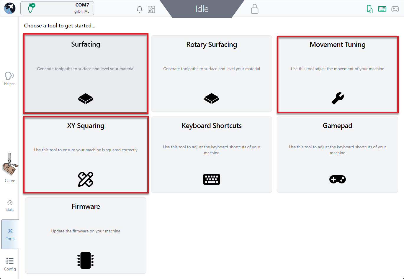
The Tool Tab is always available near the bottom left of the screen. Here you’ll find some tools that you can use to make finer adjustments to your machine for improved performance:
- XY Squaring
- Movement Tuning
- Surfacing
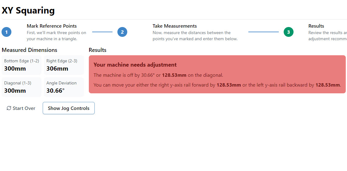
XY Squaring
When setting up any CNC, like when mounting a LongMill to a table, usually a squaring step is needed to ensure cuts don’t come out skewed. This Software Wizard (step by step guide) is a great asset to help speed things up by turning a typically ‘guess-and-check’ process into some easy measurements and behind-the-curtain math in 3 main steps:
- Mark 3 points on your machine to make a triangle (the larger the triangle, the better)
- Measure & enter the distance between the triangle points
- See the results and adjust accordingly
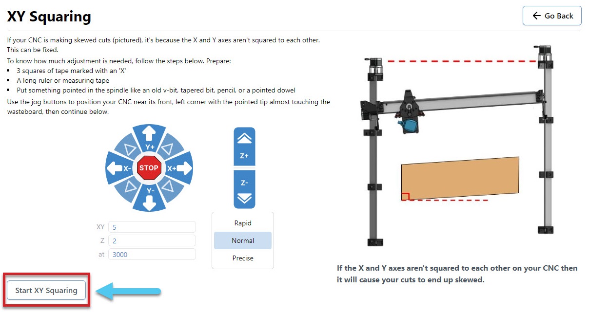
You will need the following:
- Ruler or measuring tape
- Tapered bit or V-bit
- 3 tape pieces marked with an ‘X’
- Jog the machine to the front left corner, with the bit raised slightly over the surface of your wasteboard
- Mark the point with tape marked with an X, and move the machine as directed (Default 300mm)
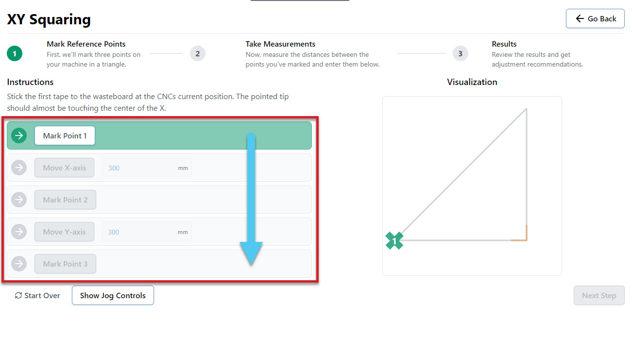
- Continue to mark points and move the machine until all boxes are complete and your triangle is marked
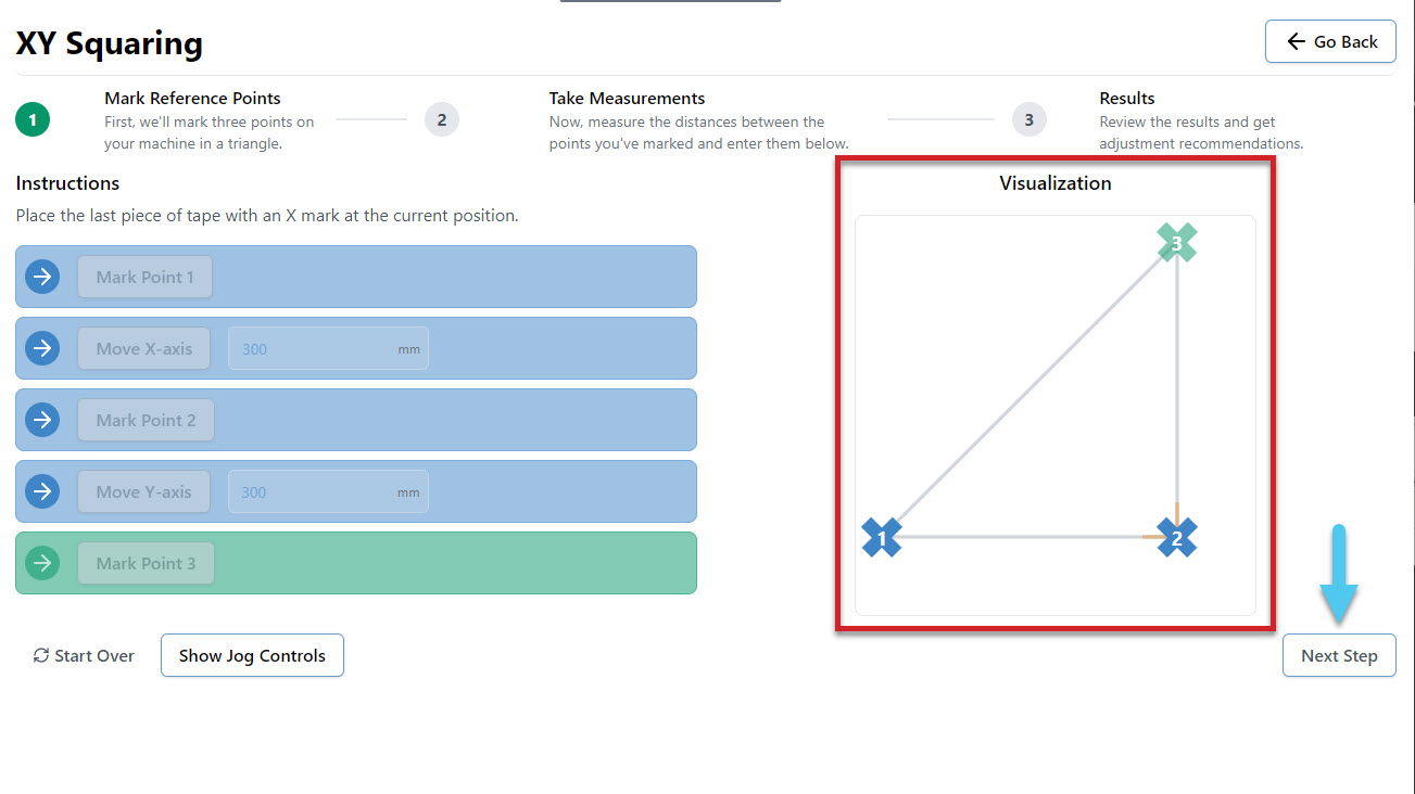
- Measure the distance between each X and enter the values into the 3 boxes. For instance you might measure 306mm, instead of the expected 300mm. Hit the Confirm button to move to the results page.
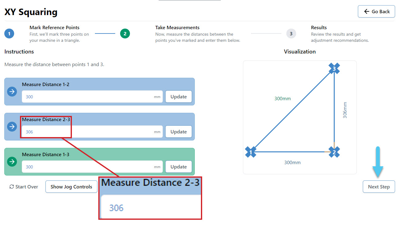
- At the end you’ll be told how square your machine is and whether you need to take action to adjust it further or if it’s close enough that you can leave it. The squaring tool also keeps an eye out for if your steps/mm (axis travel resolution) are off and can adjust those too.
You can also try watching how this process works in this user-made video by SparksTech!
Movement Tuning
Another Software Wizard (step by step guide) found in the Tool tab. This one is designed to help fine tune how much your motors turn to improve the accuracy of your machine movements. This is done through modifying the EEPROM settings stored on your CNC. You can tune the X, Y and Z axes individually.
You will need:
- Marker or tape
- Measuring tape
- Jog your machine to the middle of whichever axes you choose to tune, so that there is enough room to complete this procedure. For example, on the X-axis you would jog halfway on the X-axis rail
- Select what axis to tune on the drop down menu
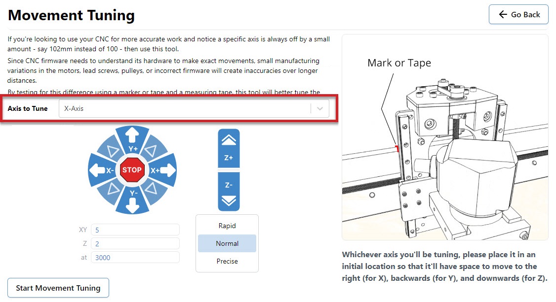
- Mark down the starting location as a reference point on the machine. For example the X-axis tuning references the edge of the XZ gantry on the X rail.
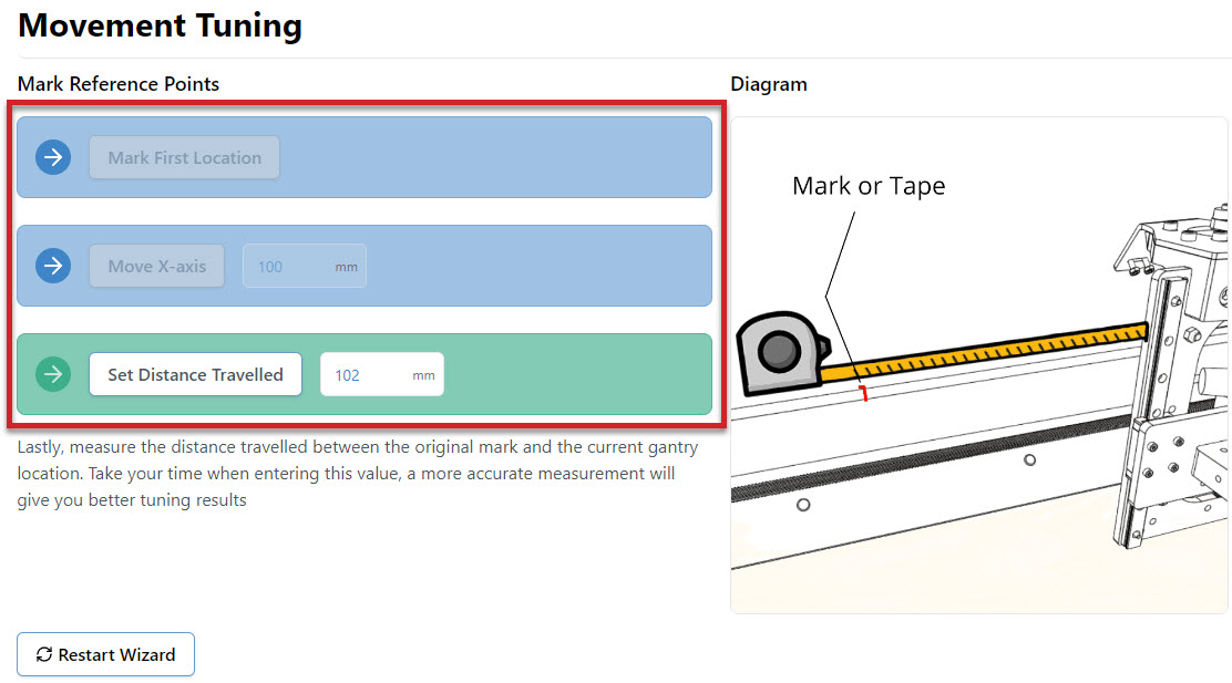
- Move the axis a chosen distance (Default 100mm)
- Measure the distance between the starting location and the finishing location
- Enter the measured value into the Set Distance Travelled box
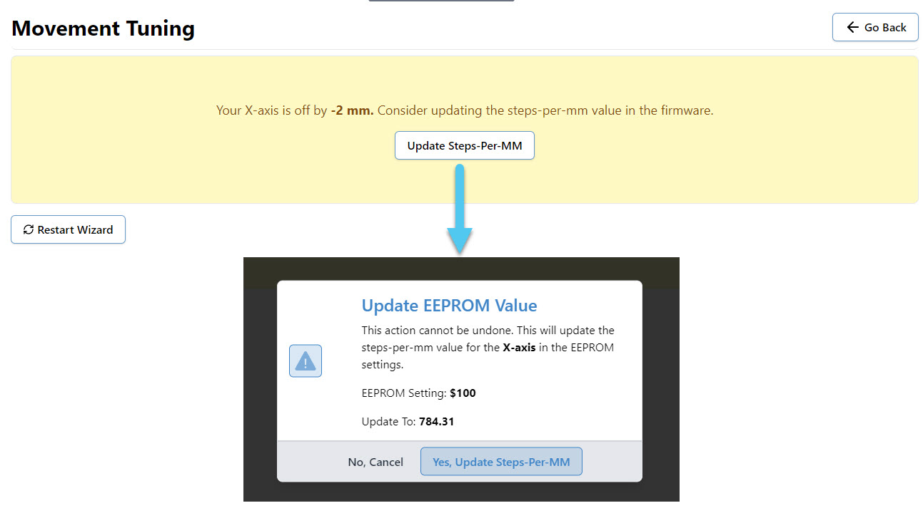
- You can now change the EEPROM setting if recommended by the procedure by pressing Update Steps-per-MM. This will bring up a popup that explains the change about to be made, and allows you one last chance to cancel the update.
- Repeat the procedure for each axis you wish to tune
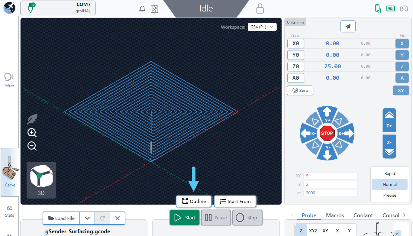
Surfacing
Surfacing the wasteboard of your machine or any project or blank material, can easily be done right inside gSender from the Tools tab! This saves the hassle of drawing rectangles in your CAD/CAM program and moving files around until you get the settings right. It’s also great for creating a perfectly flat surface of your starting materials, just like a jointer or surface planer would. You can also use the Rotary Surfacing Tool if you are wanting round stock off a rotary axis.
If you plan to use this tool to surface your wasteboard or larger pieces of material, some extra advice we’d give is to remove any accessories that might get in the way of your machine travelling to its limits as well as have a good vacuum on hand because surfacing can get really messy.
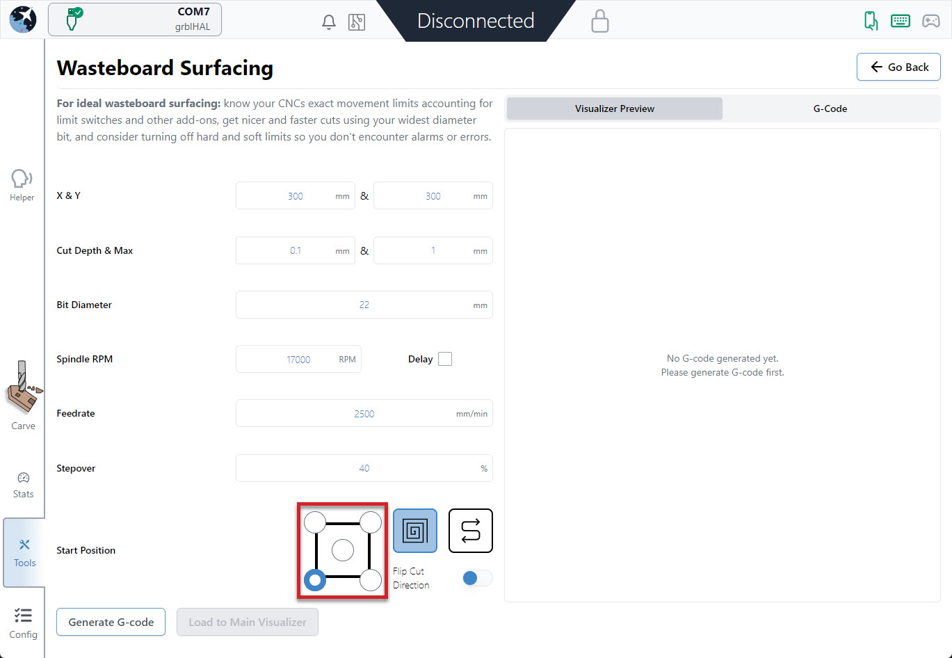
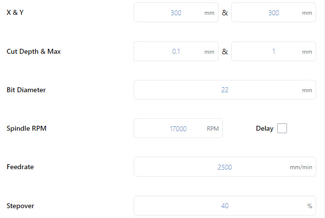
- Start by entering the settings you’d like to use to generate your surfacing job on the left side:
- X & Y: decides the cutting size (width and depth) you want to surface. If you’re surfacing your wasteboard, use the manufacturer’s spec on max machine travel or manually jog to the limits to cover the full cutting area, or if you’re surfacing a piece of material then you can use a measuring tape.
– AltMill: 1265mm (49″) x 635mm (25″) or 1251 (49″)
– LongMill MK2: 818mm (32.2”) or 1278 (50.3”) x 366mm (14.4”) or 866 (34.1”)
(if using limit switches, remove about 8mm/0.3” in X and 11mm/0.43” in Y)
– LongMill MK1: 320mm (12.6”) or 805 (31.7”) x 344mm (13.54”) or 844 (33.23”)
(if using limit switches, remove about 35mm/1.38” in X and 24mm/0.94” in Y)
(if using magnetic dust shoe, remove about 34mm/1.34” in X)
– Mill One: 235mm (9.25”) or 257 (10.1”) x 185mm (7.28”) - Cut Depth & Max: describes how deep you want to cut per pass and the total depth you want to cut down. For larger surfacing bits usually you should keep cut depth below 1mm, max depth should be increased to a couple millimeters if you think your material is very warped.
- Bit Diameter (typically 6 – 25mm): make sure you have the right bit for the job like a surfacing tool or a large, flat end mill since this will give you a better surface finish.
- Spindle RPM (default 17000): only applies if you have an automatic speed control, otherwise set this manually on your router.
- Feed rate (default 2500mm/min): influenced by the RPM, step over, bit diameter, and cut depth. Luckily if you set it incorrectly you’ll be able to override it during the job since surfacing can cause burning when cutting too slow or can have worse surface finish when cutting too fast.
- Stepover (default 40%): sticking around 40% tends to be a good balance between speed (using a higher %) and better surface finish (using a lower %).
- X & Y: decides the cutting size (width and depth) you want to surface. If you’re surfacing your wasteboard, use the manufacturer’s spec on max machine travel or manually jog to the limits to cover the full cutting area, or if you’re surfacing a piece of material then you can use a measuring tape.
- Decide where you want to start surfacing from by clicking any of the corners or the center. In most cases the front, left of the machine is the most convenient, and is the default setting. You can also select a surfacing pattern of spiral or zig-zag. The spiral will only cut from the inside-out if the start position is the centre. If you toggle the flip cut direction, the spiral will cut conventional instead of climb, and the zig-zag pattern will cut vertically instead of horizontally.
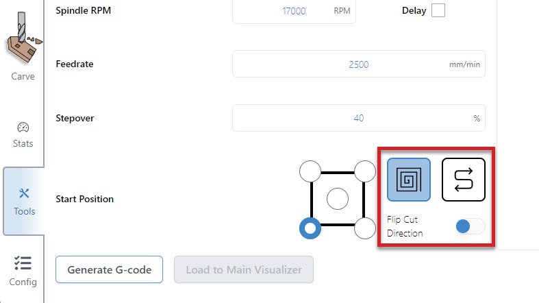
- Press ‘Generate G-code‘ and check your surfacing tool path using the ‘Visualizer Preview’ tab. You can also see the raw g-code using the ‘G-code Viewer’ tab and can copy and save it to a g-code file if you’d like to use it again later.
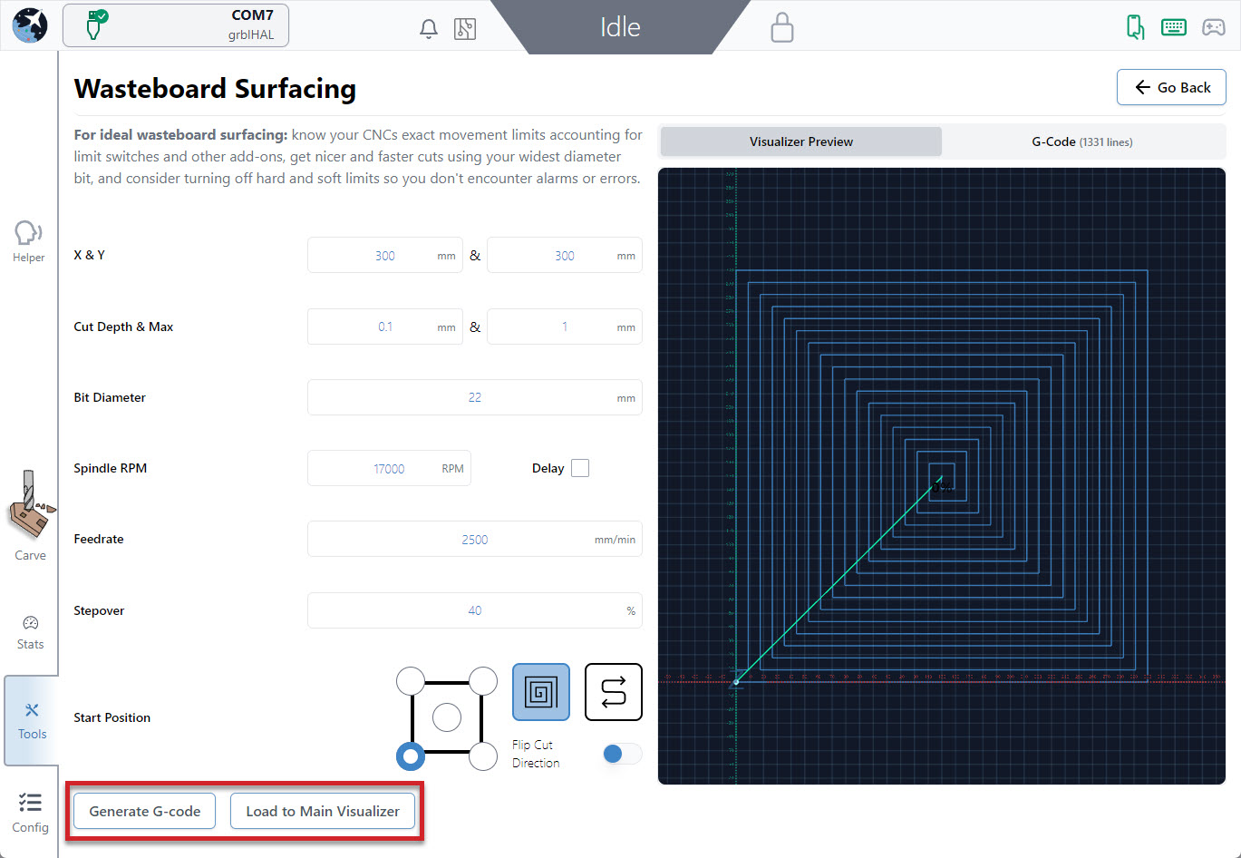
- Press ‘Load to Main Visualizer‘ to bring the g-code into gSender’s main screen. Make sure that you jog to the starting point and set your zero in the right place before starting the job. You can also press the ‘Outline‘ button as an easy way to check that you’ll be surfacing where you expect and if you find the dimensions aren’t correct you can always re-open the surfacing tool, tweak the size, and try again. Feel free to start the job whenever you’re ready!
Spindle & Laser Support
Similar to the manual coolant control, this area is for manual control of a spindle or laser outside of g-code sending. If you have a spindle or laser, you can activate these controls by going to the Config tab ➜ Spindle/Laser section. Here you can enable these functions by flipping the ‘Spindle/laser controls’ toggle. Don’t forget to apply your new settings!
Back at the main Carve screen, you’ll see the ‘Spindle/Laser’ tab at the bottom right. Here you can click to toggle between ‘Spindle Mode’ and ‘Laser Mode’, changing your grbl settings for you and displaying buttons specific to each device. For each mode there is also a warning that will appear in the right, top bar of gSender to inform you if the spindle or laser are active. This will happen both during manual control but also during job sending.
In ‘Spindle Mode‘ you can select your current spindle, adjust the spindle speed with a slider, spin it up in either direction, and stop it again with the ‘Stop’ button. These are all based on g-code commands that can also be entered into the console manually if desired. The speed slider is set from your grbl firmware settings, so max and min speed can be altered in the Config ➜ Spindle/Laser.
‘Laser Mode‘ is very similar, allowing for On/Off control, a slider for setting the laser power during manual control, and a ‘Laser Test’ button. The laser testing function is handy when troubleshooting your laser setup or for other sorts of locating and alignment because it only enables the laser for a short time before turning it back off again. Though this is much safer than regular on/off control, we still highly advise that you have you have a hand on a kill switch or E-stop during testing or control of either Laser or Spindle modes so that in case something goes wrong with your computer or the program they can still be safely deactivated.
Laser Diode Support
Some accessories can be really handy to add to a CNC router like a laser diode, drag knife, or pen plotter. These would all perform better on a faster, dedicated machine, but for occasional use why not use the existing motion system of the router to do other things for you? A laser diode in particular can be great because you can clamp the material to carve and then laser engrave afterwards and know that everything is still aligned.
Since many CNCs are coming with diode accessories, gSender has some unique features to also support lasers. Once ‘Laser Mode’ is turned on, gSender will:
- Automatically apply an offset from the router/spindle to the laser so all your g-code files stay aligned (configured in the Spindle/Laser settings, or with Firmware settings $741 and 742 on the SLB).
- Turn on the laser at low power when running a job outline (enabled in the Spindle/Laser settings). This will help you to better see where your project is going to be located on the material.
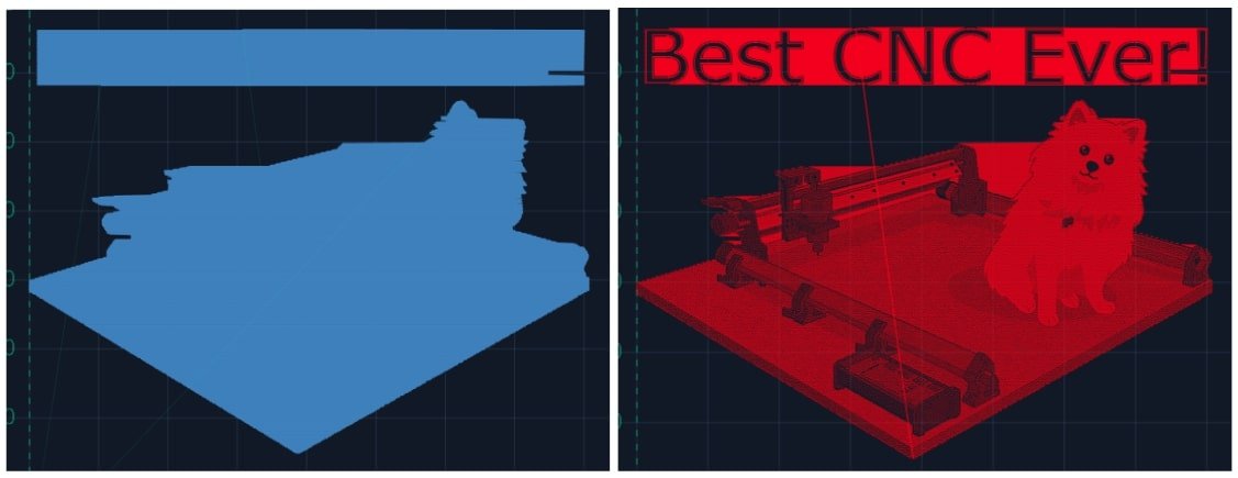
- Switch to a specialized visualization designed to show raster engraving images better than typical g-code visualizers. Seeing the laser intensity in the movements is very useful to get a better idea of what your projects are going to look like when they’re run. This will only apply to files loaded after ‘Laser mode’ is enabled, where you’ll see the colour change from the default blue to red.
Coolant Control / IOT Relay
If you have a coolant control pin on your CNC machine, gSender has a tab for manually controlling it. Under the ‘Coolant’ tab on the main Carve screen, you can find the ‘Mist’ and ‘Flood’ buttons to activate the different modes of coolant use, as well as an indicator for whether the coolant function is active or inactive. This indicator also functions during job sending. You can turn off both coolant pins by pressing the ‘Off’ button.
Many hobby CNCers don’t have a need for coolant and so prefer to use these outputs for controlling other periphery. The most common is an IOT relay that can be used to automatically control a vacuum for dust collection, the CNC’s router, LED lighting, and more. See an example of how to set that up here: https://resources.sienci.com/view/lm-iot-relay/
Homing / Limits
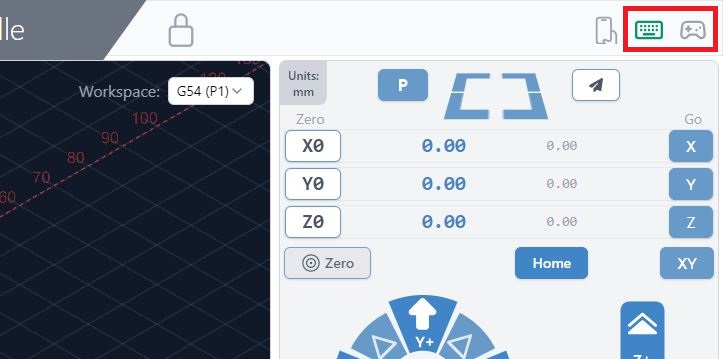
Before getting into the weeds on how you can set up limit switches and homing on your CNC for various benefits, it would be good to briefly cover some of the basics:
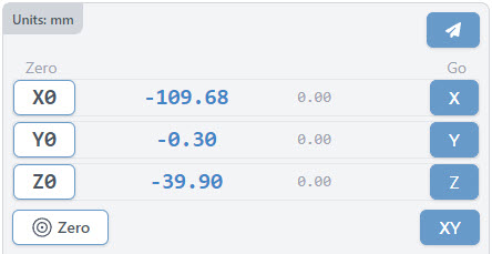
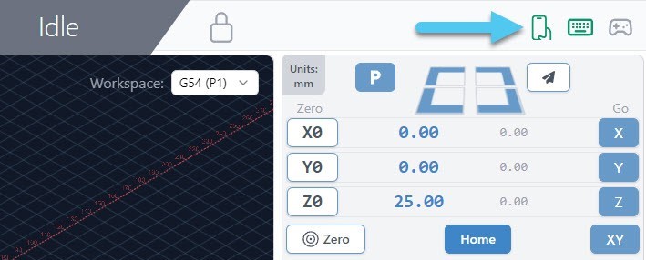
- On the main Carve page, above the jog controls, you should see a set of numbers and buttons that make up your machines ‘DRO’ (Digital Read Out). You can think of it as similar to a car navigation system.
- The buttons around this area allow you to make quick movements (blue buttons) and set the blue numbers back to a value of 0.
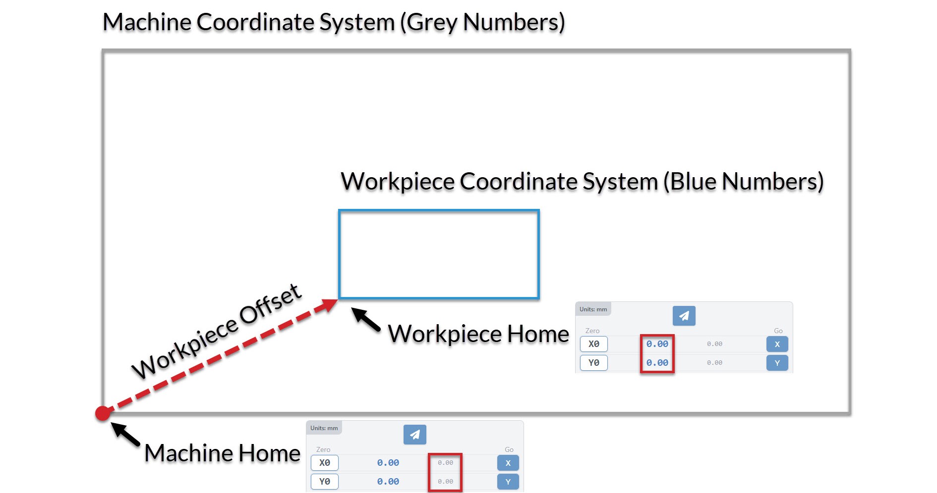
- You’ll see two sets of numbers, where the blue ones on the left are your Work Coordinates and the gray ones on the right are your Machine Coordinates; these are the two primary coordinate systems that guide a CNCs movements.
- A CNC’s Work Coordinates are very often used/edited in day-to-day cutting since they describe the exact location of the project that you’re planning to cut.
- This is effectively the ‘working area’ of your project.
- Once you’ve placed your material on the machine bed, you’ll bring the cutting head to the starting point for the project (also known as the ‘zero point’ or ‘origin’) then let the machine know that it’s now at the starting location.
- When you’re at the starting location for your project, the work coordinates should all read as ‘0’, but if you manually move your CNC to the left, down, or towards you then the number will start to decrease, or they’ll increase if you move right, up, or away from you.
- The Machine Coordinates starts to become more important once you’ve set up Homing on your CNC
- These numbers are very similar to work coordinates, except they describe the ‘working area’ of the CNC itself.
- This means that once you turn on your machine and home it, it’ll now know exactly where it’s located within its physical size constraints, it’ll also know the exact offset between the homing location and the location of your work coordinates.
- This starts to become powerful because you can then do things like resume cutting your job after a loss of connection or power-outage for example. Using homing and machine coordinates gives your CNC the memory of its location no matter the circumstances.
- Using machine coordinates without homing is also still possible, but you’d need to bring your machine to a reliable location using probing or some other method, then power-cycle the machine, since without homing the machine coordinates are set at the time the machine first powers on.
Workspaces
Another concept worth mentioning is workspaces. Usually you would only have one ‘zero position’ per project, but what about cases where:
- You need to reorient your material to cut at it from a different side
- You plan to do a series of carves that require different zero positions
- You want to align your projects to jigs you’ve fixed to the CNC bed
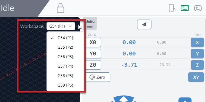
In these cases, workspaces are basically the ability for you to set multiple work coordinates that your machine will remember and can toggle between. All you have to do to use these is select a new workspace using the dropdown on the Carve page, after which everything else will continue to behave as normal including zeroing, probing, running files, and more.
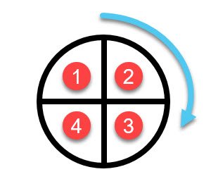
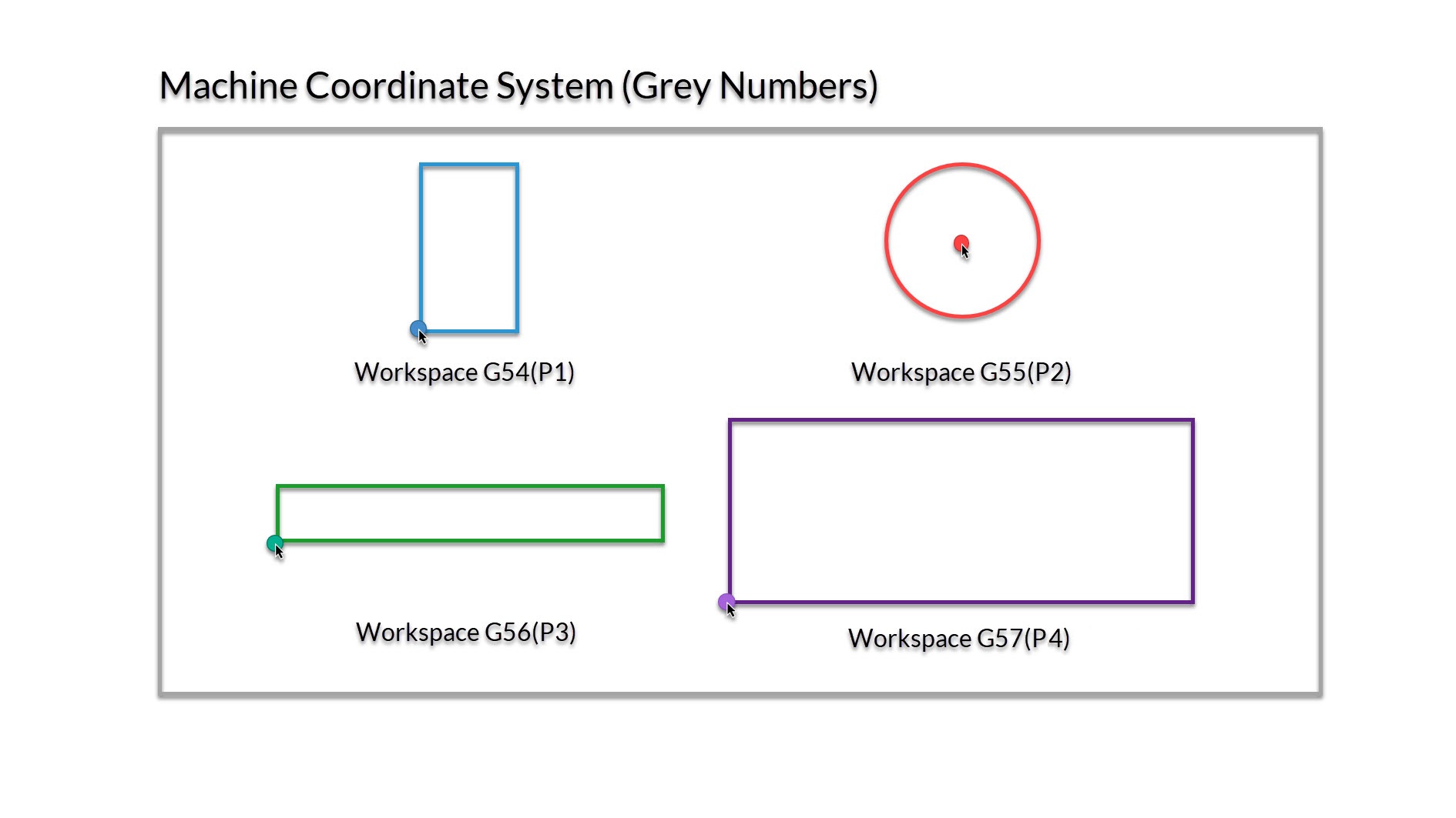
In the image below you can see a demonstration of setting up 4 different workspaces to align to jigs on the wasteboard of the CNC. Each of these has their zero set to the bottom left corner, except the circle jig which has the zero placed at the middle.
This is also discussed at about 5:30 of the video below:
Setting up Homing
The summary of the benefits of homing is that it allows your CNC to reliably know its own location. This provides many benefits like job recovery and using workspaces for more complex jobs or batch cutting. To get homing working on your CNC, you’ll need:
- Limit switches (also referred to as end stops or homing switches) which are installed at one or both ends of each movement axis of the CNC. You can see an example of these on our store.
- Homing enabled in firmware which can be done through the Config tab
- Machine limits set up to match the physical travel distances of your CNC
- Any other customization you’d like to make for your particular setup
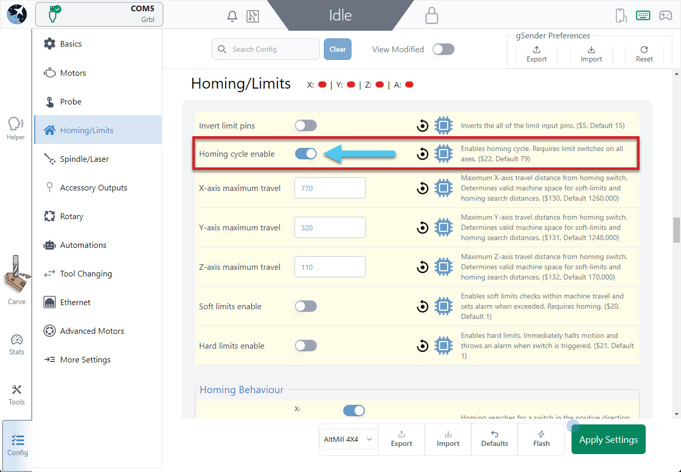
Going to the Config Tab and scrolling to the Homing/Limits section you’ll see an option to turn Homing on:
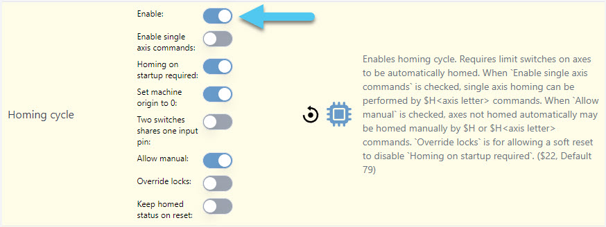
grblHAL machines will also have additional options to choose from, like homing single axes, requiring homing on startup, set machine origin to 0, and more. Typically you’ll at least want to turn on ‘Set machine origin to 0’.
While you’re here, we’d also recommend that you use the lights at the top of the Homing/Limits section to check that all your limit switches are plugged in and working correctly. They should be red by default and light up green when they’re triggered, and if that’s not the case then you might want to change your settings or check your wiring.
Once you apply settings, you’ll find back on the main Carve screen that there are some new buttons available:
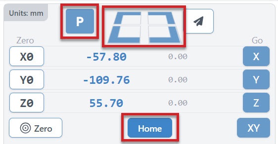
- The Home button will help you to manually home your machine any time you need (sends the typical $h command). For your first time homing, have your hand on the machines E-stop in case the homing goes the wrong direction. Many machines home to the front left corner or the back right, so if your machine is behaving incorrectly then go back to Config to adjust your homing directions.
- Four Rapid-Travel buttons to move your CNC at its maximum speed to any of your machine’s 4 corners (offset by 5mm). These should only be used once your machine is homed and you’ve correctly set up your machines maximum travel.
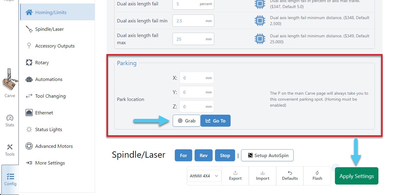
- A configurable Park Location that acts similarly to the Rapid travel buttons but instead moves to a custom location you set yourself. To set up your parking spot, go to Config ➜ Homing/Limits and scroll down to the bottom of the section. Here you can enter the coordinates of your parking spot manually, or move your router/spindle to the spot you wish to park and hit the Grab current position button. Test out your new spot by hitting the ‘Go to’ button in settings or hitting the ‘P’ button on the DRO. Don’t forget to hit the Apply Settings button to save your new spot!
Setting Limits
Things like machine limits for the Machine Coordinate system are usually set up by the manufacturer and so might never need changing. There are cases though where depending on your model or if you’ve assembled a kit and installed add-on your maximum travel area might need to be adjusted to properly reflect your machines travel limits.
We recommend you do this especially if you’re planning to use the ‘quick-travel’ buttons. You can find these settings by going to Config ➜ Homing/Limits ➜ X-axis maximum travel (Y, Z-axes are here too). Remember to hit the Apply Settings button afterwards.

If you’d like more information on how to set up and use limit switches, read here: https://resources.sienci.com/view/lm-adding-limit-switches/
Soft Limits
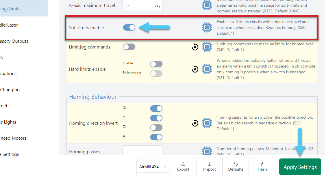
With homing working, you can optionally choose to turn on soft limits. This feature will keep an eye out after you home your machine to see if any movements are trying to go past your machine limits, and stop those movements from happening to protect your machine. Enable these in Config ➜ Homing/Limits ➜ Soft limits enable. Don’t forget to hit the Apply Settings button to save!
Hard Limits
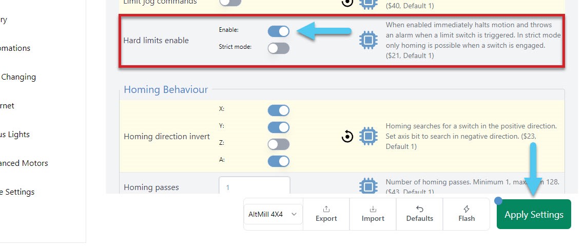
If you have a sensor on both sides of each axis, all 6 sensors can provide you a hardware backup solution, to the software solution provided above with the soft limits. With hard limits on, if your machine get’s close to the edge of an axis, your sensor will trigger, stopping any further movement. Enable this in Config ➜ Homing/Limits ➜ Hard limits enable.
Stats Tab
Curious to know how many jobs you’ve completed, how many hours you’ve put on your machine, what alarms you’ve encountered or what maintenance you should be focusing on? Think of the Stats tab as your dashboard for understanding how your machine is running, what things you might need to check up on, or to collect information that would be useful for troubleshooting.
Here you can see information about your machine including job statistics, machine maintenance, alarms & errors, configuration settings, diagnostic files, resources to help along your CNC journey, or learn more about gSender. You can check out the main dashboard, click into each section to see further details using the tabs at the bottom of the screen, or click on the button in the top right corner of each section.
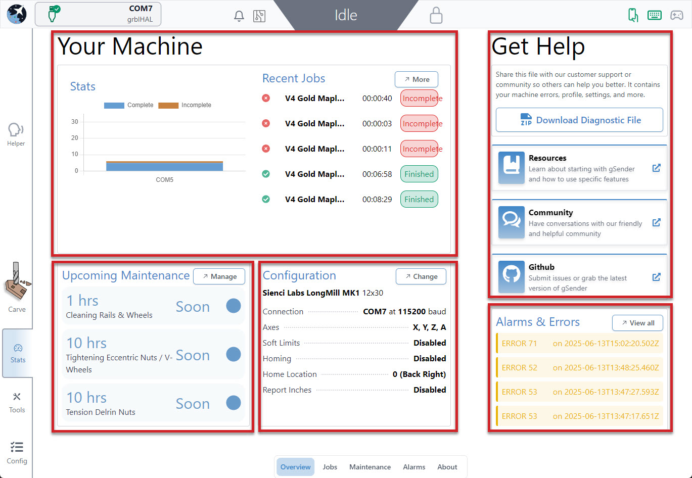
Get Help
Before moving on to the other sections in Stats, the main page can be really useful if you’ve got an issue with your machine and feel stuck. Most importantly, you can follow links to our community pages including our Resources, Community Forum, and GitHub.
Another valuable feature is the ability to download a Diagnostic File of your CNC machine. This file contains many things like your current machine settings, gSender preferences, and a PDF file that includes about your computer, your CNC, recent alarms / errors, any currently loaded g-code file, and more. It’s basically a treasure trove of information that you can share on Community Forums, Facebook groups, or with your CNC customer support. This can go a long way towards getting help from others on diagnosing any problems your CNC might be experiencing.
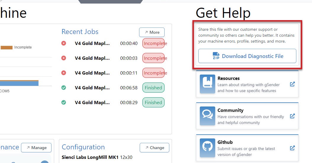
Click the ‘Download Diagnostic File‘ button to download this. This will open a save dialog box for you to save the file to a location that you can easily access to send along to others in an email, support ticket or post online.
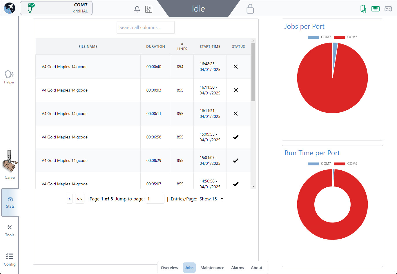
Job Stats
The Job Table provides a simplified breakdown of each job, including the file name, duration of the job, # of lines in the job, start time/date and if the job completed successfully or not. This section also displays jobs per port and run time per port. You can use the search bar at the top to search each column for a specific job by date, file name, completion status, etc.
CNC Maintenance
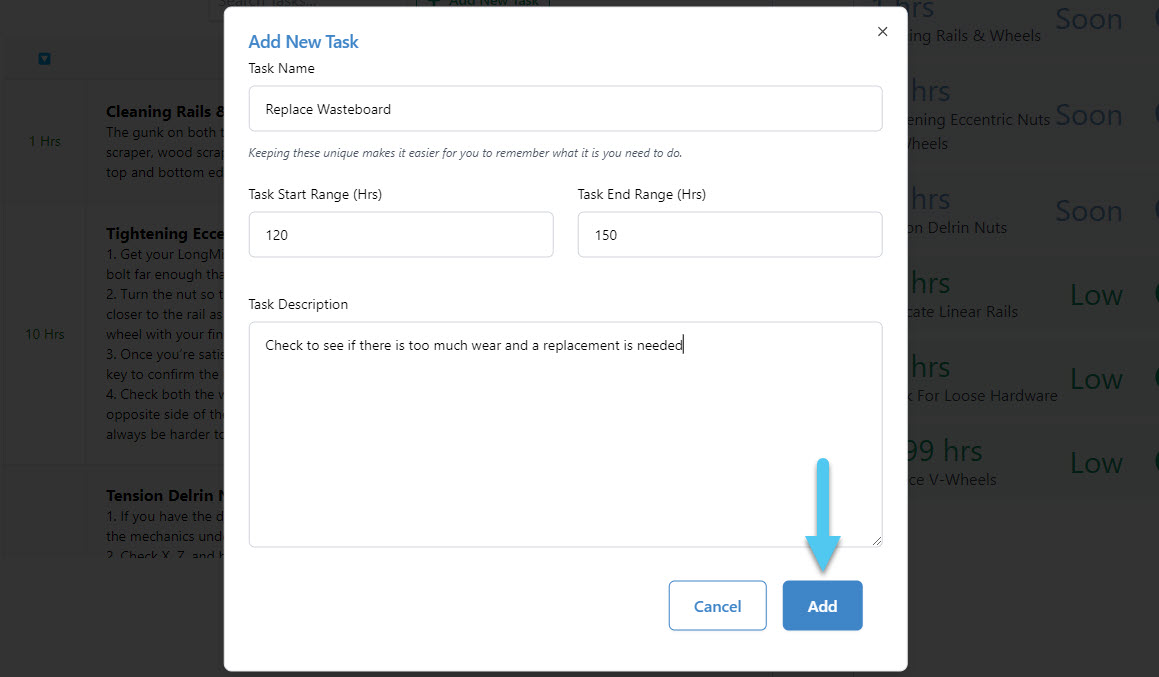
In the Maintenance tab, you will see preset tasks with an hourly countdown range, to remind you when a maintenance task is due to be performed. These times pull directly from the runtime of your jobs and allow you to mark them as complete to reset the timers. Once the task is in range, the maintenance is due, once past the range, the task becomes critical to address.
Each task includes a timer showing how much time remains before the task needs attention, detailed descriptions and an edit button or complete task button. This section also displays all upcoming maintenance in a colour coded list to the right.
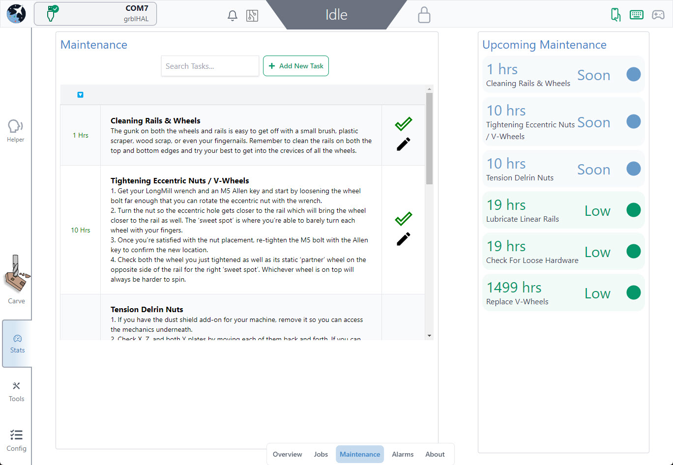
You can also add your own reminders, time due range and description to this section, to really make it your own.
Alarms & Errors
In the Alarms & Errors tab, you will see a list or errors and alarms. Details include the error or alarm number, time and date and a brief explanation of the issue. Here you can also Clear Alarms & Errors or Download a Diagnostic File for further troubleshooting.
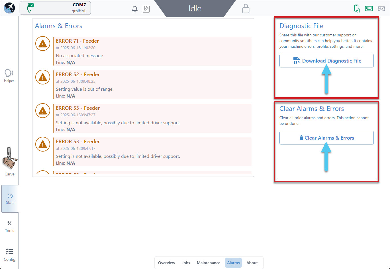
To read more about Alarms & Errors, visit our grbl Alarms & Errors resource.
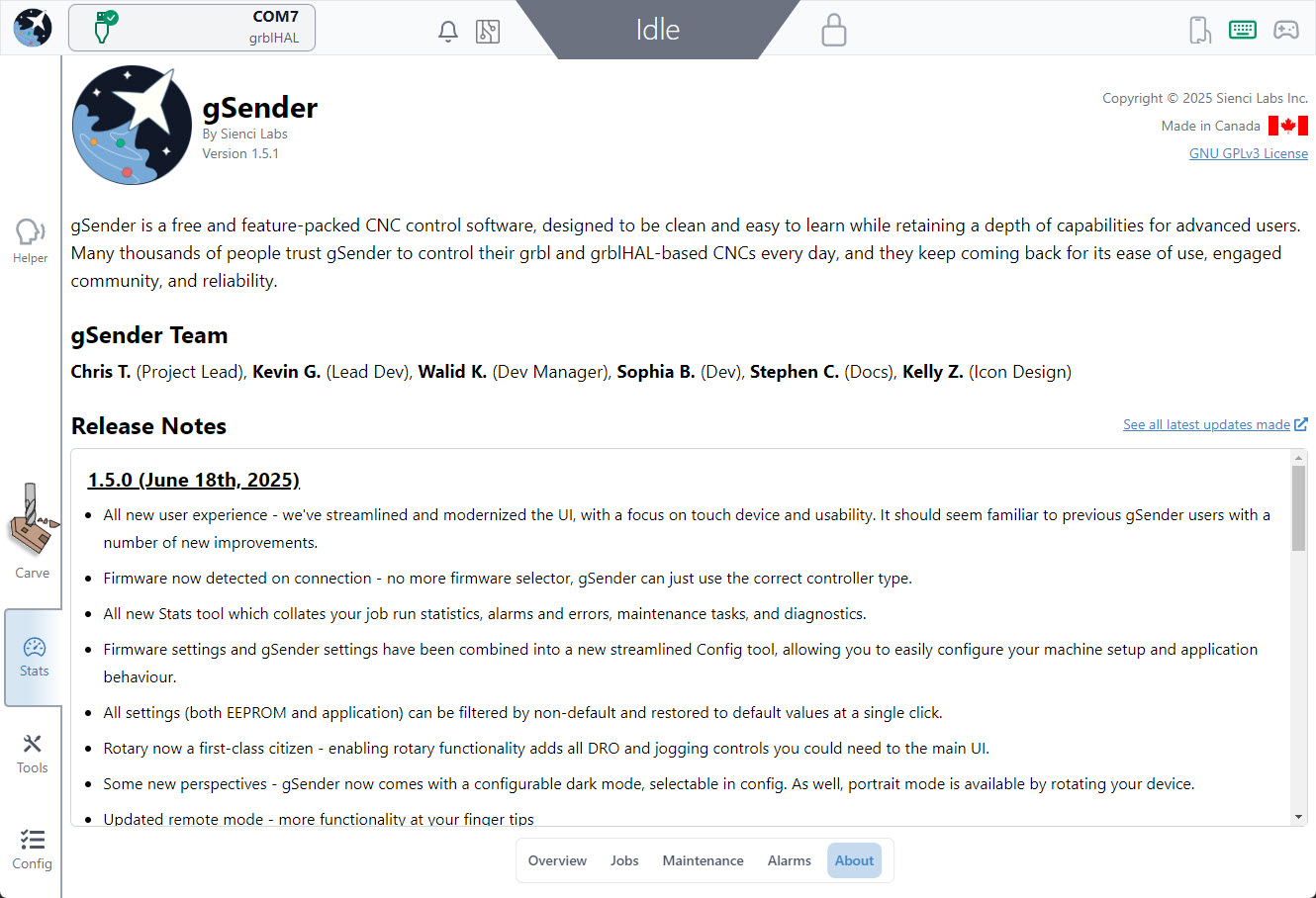
About Page
You can find the release notes for the latest version of gSender in the “About” section of Stats, as well as get to know more about the team behind gSender!
Config Tab
As introduced in Setup and Layout the Config tab is meant to act as your one-stop-shop for any customization to how gSender looks or acts, or how your CNC is configured. This starts with some basics, then moves on to motors, probing, homing/limits, spindle/laser, rotary, tool changing, and more.
The settings are grouped to make the whole setup process easier, and you can quickly navigate them by either:
- Scrolling along the page
- Clicking the table of contents links on the left side
- Type the setting you’re looking for in the search bar (for example “acceleration” or “$110”)
- Clicking the ‘View Modified’ toggle to filter by only settings that have been changed from their default
As you look through this area to get a lay of the land, you might also notice some other useful aspects:
- You’ll be able to tell which settings are firmware-based by the microchip icon next to them, the ones without a microchip are gSenders local preferences.
- There are buttons and indicators put into place so that you can change and test settings on the fly without having to leave the Config tab. This makes machine setup much faster (for example, if your CNC jogs the wrong way you can invert it, save the settings, and test that it’s working all in the same place).
- There are also some buttons that that will take you to automated setup wizards
- Any setting will highlight in yellow once it’s been changed from default and give you the option to revert it if needed
Some of the common settings to change are: preferred units (mm/inch), visualizer theme and Dark mode, enabling controls for add-ons that your machine has (spindle/laser controls, rotary controls, etc.), customizing notifications, and of course selecting a Machine Profile.
Remember to hit Apply Settings after any changes you make!
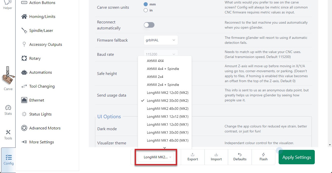
Machine Profiles
When it comes to selecting a machine profile at the bottom of the Config tab, your machine will either be ‘supported‘ or ‘unsupported‘. The only difference between these two types is that for unsupported machines:
- Firmware-based settings won’t turn yellow when they’re changed from their default (this is because gSender isn’t aware of what the default for that machine is)
- There won’t be an option to reset a firmware-based setting back to its default
- Clicking the bottom ‘Defaults’ button will revert your machine settings to standard grbl defaults
- Attempting to ‘Flash’ your machine will flash it with default grbl firmware
- You should be more cautious when using the Config tab since it could enable you to alter your machine in unpredictable ways and we won’t be able to help you with your specific hardware. In this case, if your machine isn’t working, contact your manufacturer to get their advice on how to fix it.
All other aspects of using and operating gSender will work as expected no matter what machine profile you select; but because these extra features for setting, resetting, and flashing can be useful for many CNCers we encourage manufacturers to contact us so we can add more supported machine profiles. The current list of supported machines is:
- Sienci Labs LongMill (MK1, MK2, and MK2.5)
- Sienci Labs AltMill (MK1 and MK2)
- Sienci Labs Mill One (V1, V2, and V3)
Machine settings
With your Machine Profile selected (if yours is not listed then select “Generic CNC”), the rest of the buttons at the bottom can be used as follows:
- All the bottom buttons only apply to firmware-based settings specific to your machine (the settings with the microchip next to them), not gSenders local settings
- Defaults
- Should only really be used if you’ve selected a ‘supported machine profile‘
- Acts like a “factory reset”
- Use it when you’re first setting up your CNC to ensure your settings are broadly correct, or if you want to bulk reset all settings back to their default
- Flash
- Should only really be used if you’ve selected a ‘supported machine profile‘
- Will either flash your specific machines grbl firmware, or for grblHAL boards will give you the option to upload a hex file to flash a new firmware
- Import
- If you had previously exported machine settings that worked for your CNC, you can import them to get things working again
- Export
- If you’ve configured your CNC and everything seems to be working well, save your firmware settings to a file so you have it on hand in case something goes wrong
- The process of importing/exporting is basically the same as for importing/exporting gSender preferences
gSender Preferences
These preferences are stored on the specific computer being used to run gSender and includes items like: preferred units, machine selected, probe, tools, jogging presets, keymapping, tool change g-code, automations, and more. These don’t have any impact on your machines firmware settings (settings with the microchip symbol next to them), rather they impact how you use gSender day-to-day.
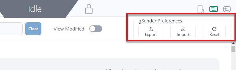
The buttons for gSender Preferences are all in the top right corner of the Config tab and be used at any time to reset all settings to default (remember you can reset individual settings if you’d like), or import or export your current gSender setup. Importing/Exporting can be useful if you’re updating to a new major version of gSender or you plan on using a different computer to run your CNC and want to carry over all your familiarities to make sure things keep running as expected.
To transfer your settings over, start by exporting a save file:
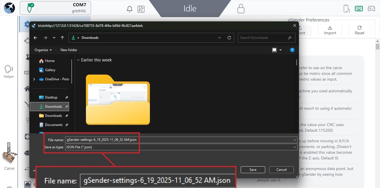
- Go to the Config Tab, and click the ‘Export‘ button.
- Save the file somewhere onto your computer that you can find afterwards
- Outside of gSender, if you plan to move the file to another computer, find the file and transfer it using a memory stick or sending it over the internet by emailing to yourself or using Google Drive or OneDrive.
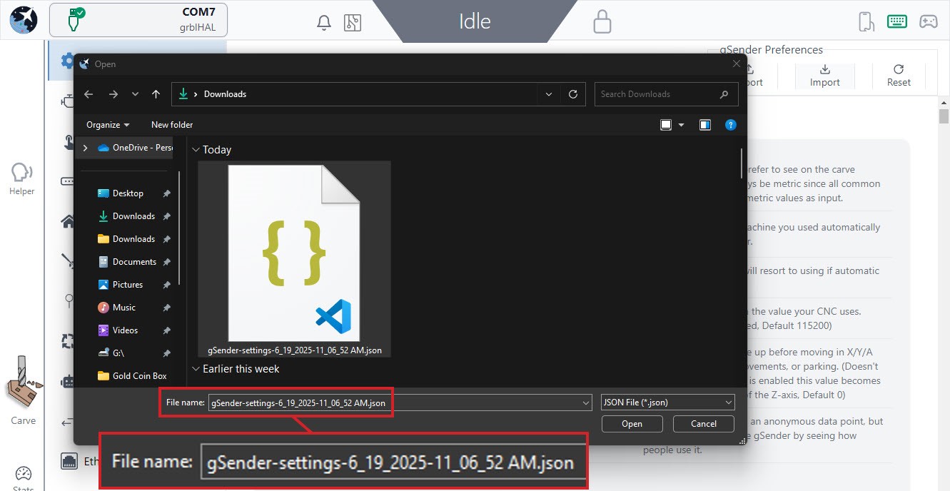
- Once you’ve got the file onto the other computer it’s now easy enough to open gSender on that computer, or in the web browser if you’re doing remote control, and go to the Config tab and click the ‘Import‘ button just to the right of the export button.
- Locate the file and click ‘Open’
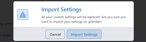
- You’ll get a warning. Click ‘Import Settings’ if you want to continue. Once you do, gSender will disconnect and you’ll need to reconnect the machine to resume operation but the settings should now be brought over.
Ethernet Connection
An Ethernet setup is a bit more involved than using USB, but if you’re looking to switch over due to its inherent reliabilities that will always make it more robust, you’ll need to make sure you have an Ethernet cable on hand and that your device has a free Ethernet port. You’ll also want to double-check since some Ethernet-driven CNC control boards like the SLB aren’t able to be firmware flashed over Ethernet, so you’ll still need to keep a USB cable handy if you need to do any future updates or recover from a board reset.
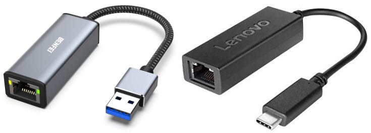
- If your computer only has one Ethernet port and it’s already used, you can try picking up a USB to Ethernet dongle or adding an additional Ethernet card. If you use the dongle, the USB side will plug into your computer, and the Ethernet side will connect an Ethernet cable that you’ll run to your board.
Ethernet on Windows
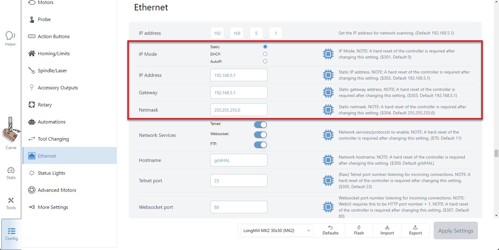
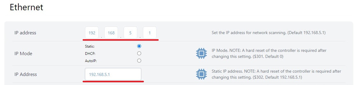
- To start, connect to your CNC over USB, open the Config tab to the Ethernet section, and copy down the numbers you see for the ‘IP address‘ and ‘Netmask‘. The defaults should be
192.168.5.1and255.255.255.0respectively, with the IP mode set tostatic.
- Once copied down, you can unplug your USB and connect the Ethernet cable directly from your PC to your board. If you look where you plugged the Ethernet cable into the board from the outside, you should see a green light on and a flickering yellow light.
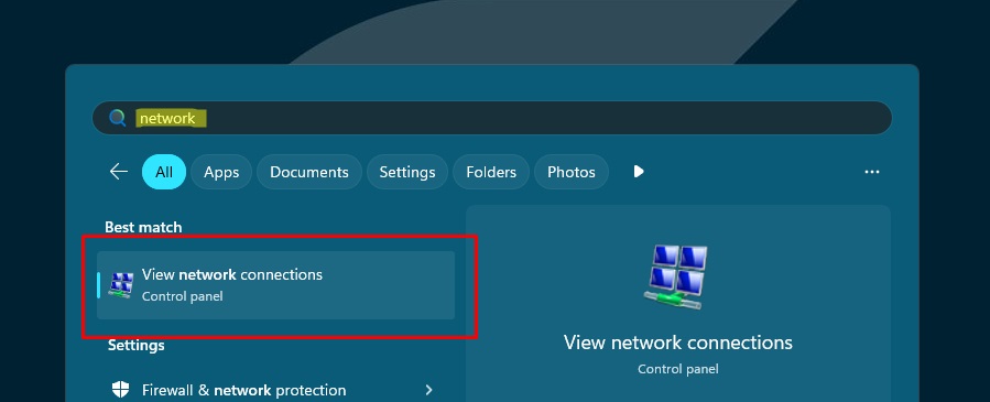
- Now you’ll need to configure the PC’s Ethernet interface. Start by opening the Windows menu, searching for “network” and click ‘View network connections‘ to get a list of Ethernet ports.
- Here you should be able to find the ‘Ethernet‘ listed that you just connected to your board. Even if there are multiple Ethernet options, unplugging and re-plugging the cable from the board will show which one it is. Once you know, right-click it and open its ‘Properties‘.
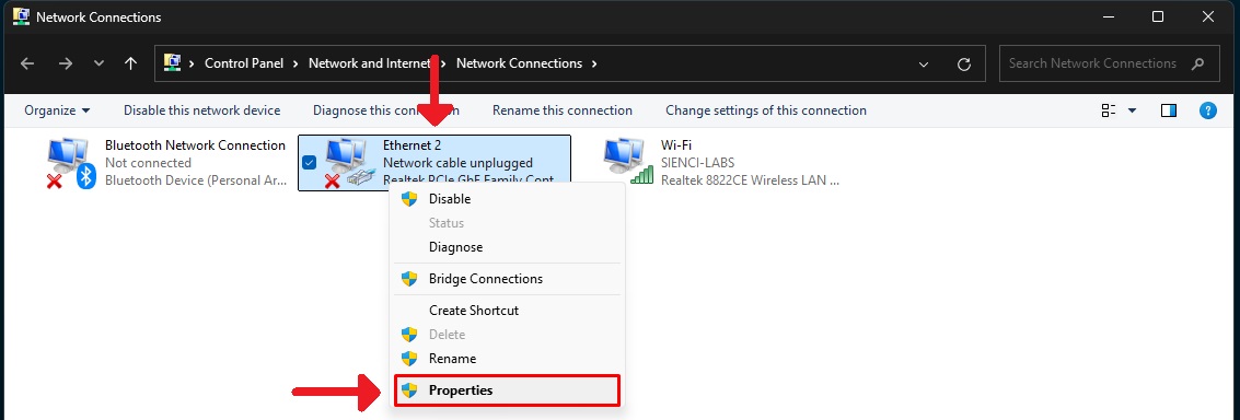
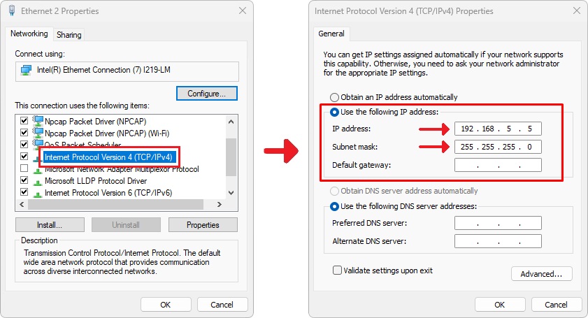
- In the Properties, find the option for ‘Internet Protocol Version 4 (TCP/IPv4)‘ and double-click it. Here, you’ll want to:
- Select the ‘Use the following IP address‘ option
- Type into ‘Subnet mask‘ the ‘Netmask’ number you copied down
- Type in the ‘IP address‘ that you copied down, just change the last number (for example, change it from
192.168.5.1to192.168.5.5) - Click ‘OK‘ to save and close the options
- Back in gSenders Config tab ➜ Ethernet section, make sure the IP address for gSender matches the IP address from the firmware.
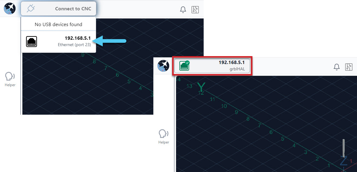
- Now click on Connect to CNC, choose the Ethernet Port option and you should see it connect successfully 🙂
- If you have a problem connecting with Ethernet, go back over the setup steps. You can also reconnect over USB to double-check your boards Ethernet settings.
Ethernet on Mac
To set up an Ethernet connection from a Mac, you’ll follow a lot of the same steps as for Ethernet on Windows but after doing Step 2:
- On your Mac, click the Apple menu ➜ System Settings ➜ then click ‘🌐 Network’ in the sidebar (you may need to scroll down).
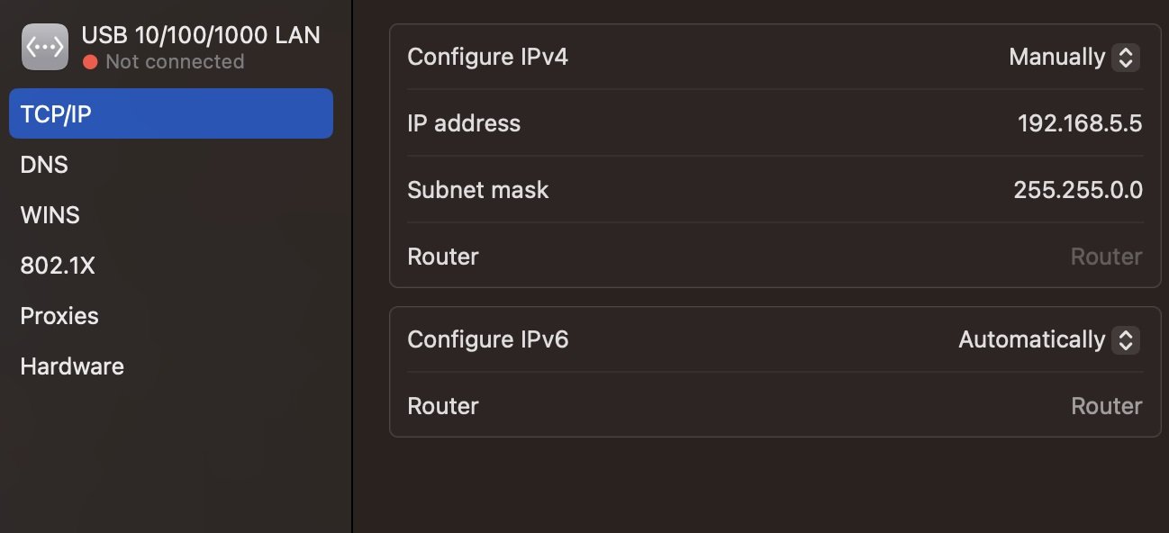
- Click Ethernet service ➜ ‘Details…’. Note: if your Mac doesn’t have a built-in Ethernet port and you’re using an adapter, look for a service that contains the name of the adapter manufacturer or the type of adapter. For example, the service might be named [manufacturer name] USB-C LAN, or just contain the model number of the adapter.
- Click TCP/IP in the sidebar ➜ then for ‘Configure IPv4’ choose ‘Manually’ so you can enter the specific IP address and subnet mask. You want the subnet mask to be the same value from the EEPROM ‘Netmask’. The IP address should have a different last digit on the same mask – so if the board is device 1 (192.168.5.1), you could call your PC device 5 (192.168.5.5). Click “OK” to save and close the options.
- Resume following the Windows instructions at Step 6 to finish the process.
Wireless Control
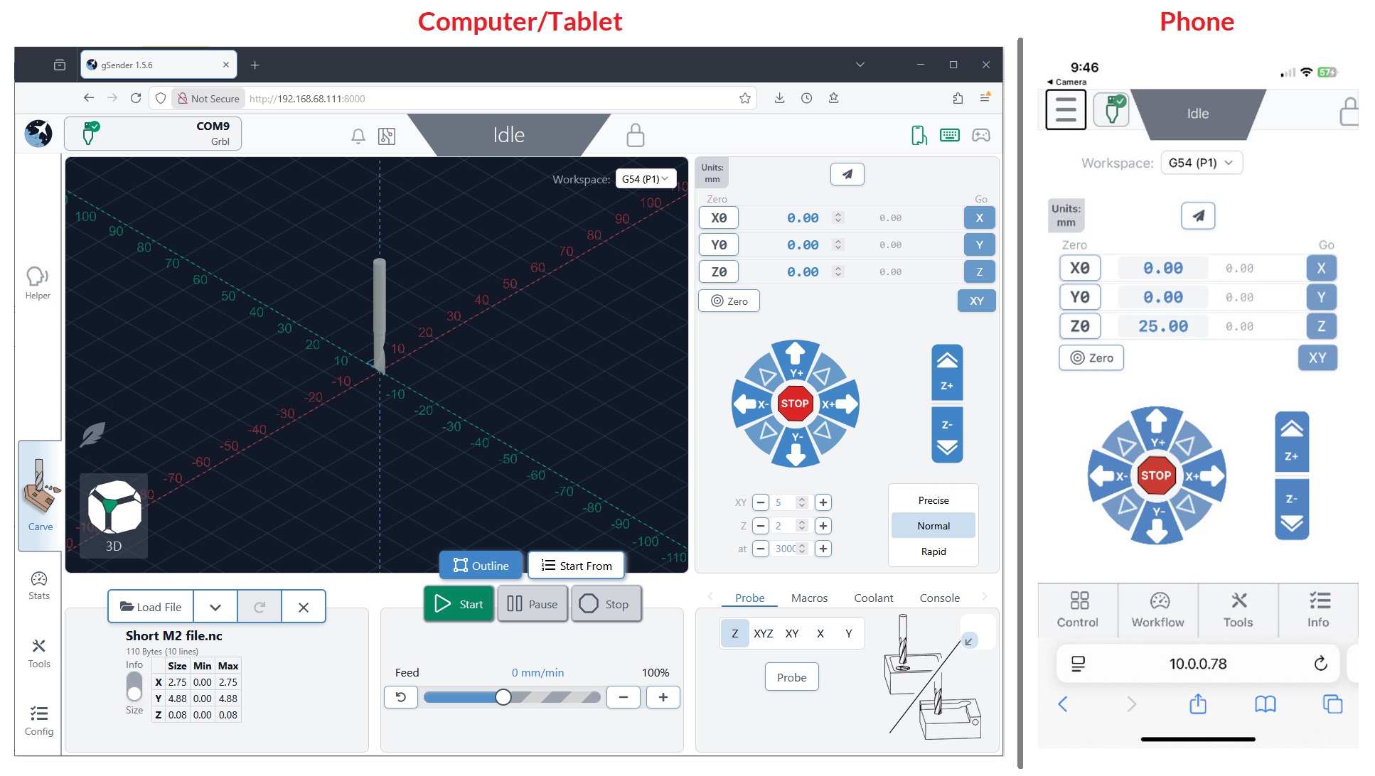
If you’ve ever wanted to run your CNC without being stuck right next to it, this is the feature you’re looking for. Once enabled, it will allow other devices on the same internet network to connect to the main computer that’s running your CNC. These ‘remote devices‘ can be anything that can connect to the internet and run a web browser, meanwhile the ‘inline computer‘ plugs into your CNC with a USB or Ethernet cable and will receive commands over the internet from the remote device.
This feature is handy if you’d like to:
- Load in a file from your design computer outside your shop then run it on your computer inside the shop
- Use a tablet as the primary means of controlling your CNC rather than a mouse and keyboard
- Use a phone for occasional use when jogging or running functions
- Leverage a mini PC or Raspberry Pi as the inline (tethered) computer for cheap, fanless, and reliable operation without taxing them with a display, keyboard, and mouse (though this still doesn’t create a fully ‘headless’ setup)
Before diving into the setup, here are some quirks and warnings that are important to keep in mind:
- Both systems need to be on the same internet network to work
- The ‘remote device‘ needs to be able to run a web browser
- The setup process can be a little more involved, so we don’t advise using this feature if you’re not confident with troubleshooting your own setup
- You may need to be an Administrator of the inline computer to make the changes needed
- If you intend to use this feature for more important projects or with expensive tools or materials, keep in mind that it will always be inherently less reliable than a hard-wired connection
- This feature is NOT intended to enable use of your CNC while AWAY FROM YOUR WORKSHOP. A CNC should always be run while you or another knowledgeable operator is in the vicinity to ensure safe machine operation and be able to react if intervention is required. CNCs can cause fires from electronics, material friction, and can have other safety hazards if not properly monitored.
Wireless Setup
All setup steps need to happen on the inline computer (the computer you’ll have connected via USB or Ethernet to your CNC) and have been simplified to mostly happen within gSender:
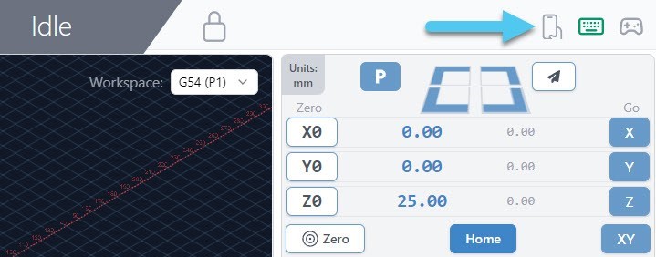
- To begin, click the cell phone icon on the top right of the screen.
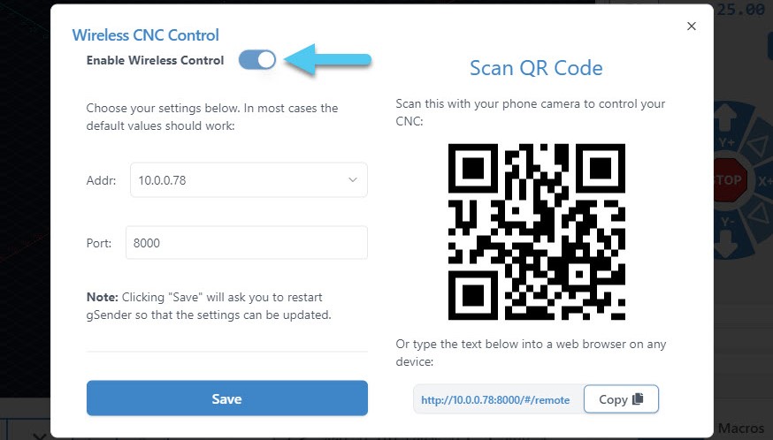
- This is where wireless control is set up. First, click the ‘Enable Wireless Control‘ toggle. Second, you’ll see the boxes for ‘Addr’ (address) and ‘Port’ become available. The default values for these should work but if you have a particular setup or require troubleshooting then consider changing these.
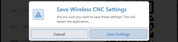
- Once you click the ‘Save’ button, gSender will automatically restart in order for the changes to take place.
- You’ll know the setup was successful if gSender restarts and the remote connect icon is green.
- To connect with your ‘remote device‘, click the cell phone icon again to open the wireless control settings. If you plan to use a phone, use the camera to scan the QR code, and for any other device ‘copy’ the text at the bottom right into the address bar of a web browser like Chrome or Edge. After the page loads, you should see a copy of gSender running in the web browser!
- If there was a problem during setup, then you might’ve encountered a firewall or unavailable port. Solutions to these are covered in the troubleshooting section.
Using gSender Remotely
With setup complete, regular use is very straightforward:
- As long as your ‘inline computer’ is on and connected to your CNC, and your CNC is powered on, then re-using the same text on the web browser of any device will give you access to a copy of gSender running fully remotely. Example text could look like this “192.168.68.155:8000” where for the phone interface it would have “/#/remote” added onto the end.
- For phones and tablets, it can also be easy to re-use this webpage by saving it to a bookmark on your home-screen so you can open Remote gSender easily anytime you want! Check out this video for details.
- Once connected, you’ll be able to control your CNC remotely with most of the same features and functions you’d normally expect:
- Use both the remote and inline devices simultaneously to control your CNC like jogging, opening and closing files, probing, macros, and more
- Notice that both their screens look exactly the same so you can watch the visualizer move around or check on the machine state
- On phones the screen will look different since we’ve optimized it for jogging, setting zeros, and probing
- When you click to ‘load a file’ you’ll only be able to load files from the device you’re currently on, don’t expect to gain access to the files stored on the opposite device. However once the file is loaded into gSender, you’ll be able to run it from any device.
- There can be multiple remote devices all connected to the same inline computer at the same time to control your CNC from multiple devices. There can also be multiple inline computers controlled from the same remote computer, giving you multi-CNC control from the same device.
- Some gSender-specific ‘local’ settings like won’t carry over to the remote device so if you want to make sure files are run the same way every time you’ll need to transfer your gSender settings over by following the ‘Transfer Settings’ instructions
Troubleshooting
If you ran into issues during remote control setup, here are some checks you can make:
- Make sure you have gSender open, have gSender connected to your CNC, and you’ve turned wireless control on
- Ensure both your computers / devices are on the same internet network and the IP numbers match on both devices
- If on the remote device you get a popup for “Server Connection Lost”, this just means that either gSender on the inline computer was closed or the shared internet is disconnecting. You should be able to fix this by restarting gSender on the inline device, then clicking “Attempt Reconnect” on the remote device.

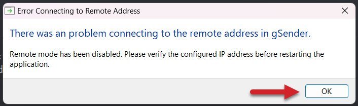
- If there was a problem using the specified IP address or Port, you’ll get an error window to let you know. In this case you should be able to reopen gSender, go back to the Wireless Control settings, and try another IP or Port until the setup is successful. Common port values are 3000, 8000, and 8080 and generally don’t go below 1024 since those are considered privileged. Changing IP addresses can also help if you’re running a VPN or need a different internal IP to external IP mapping.
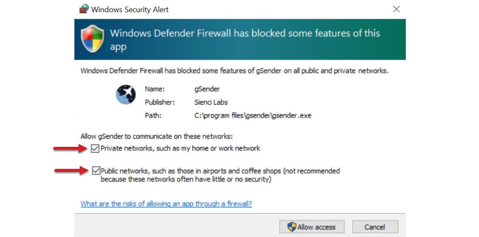
- If you have a Windows Security Alert window pop up during setup, it means your inline computers firewall isn’t allowing gSender to communicate to other devices on your network.
- Check the boxes beside “Private networks” and “Public networks” and click the ‘Allow access’ button
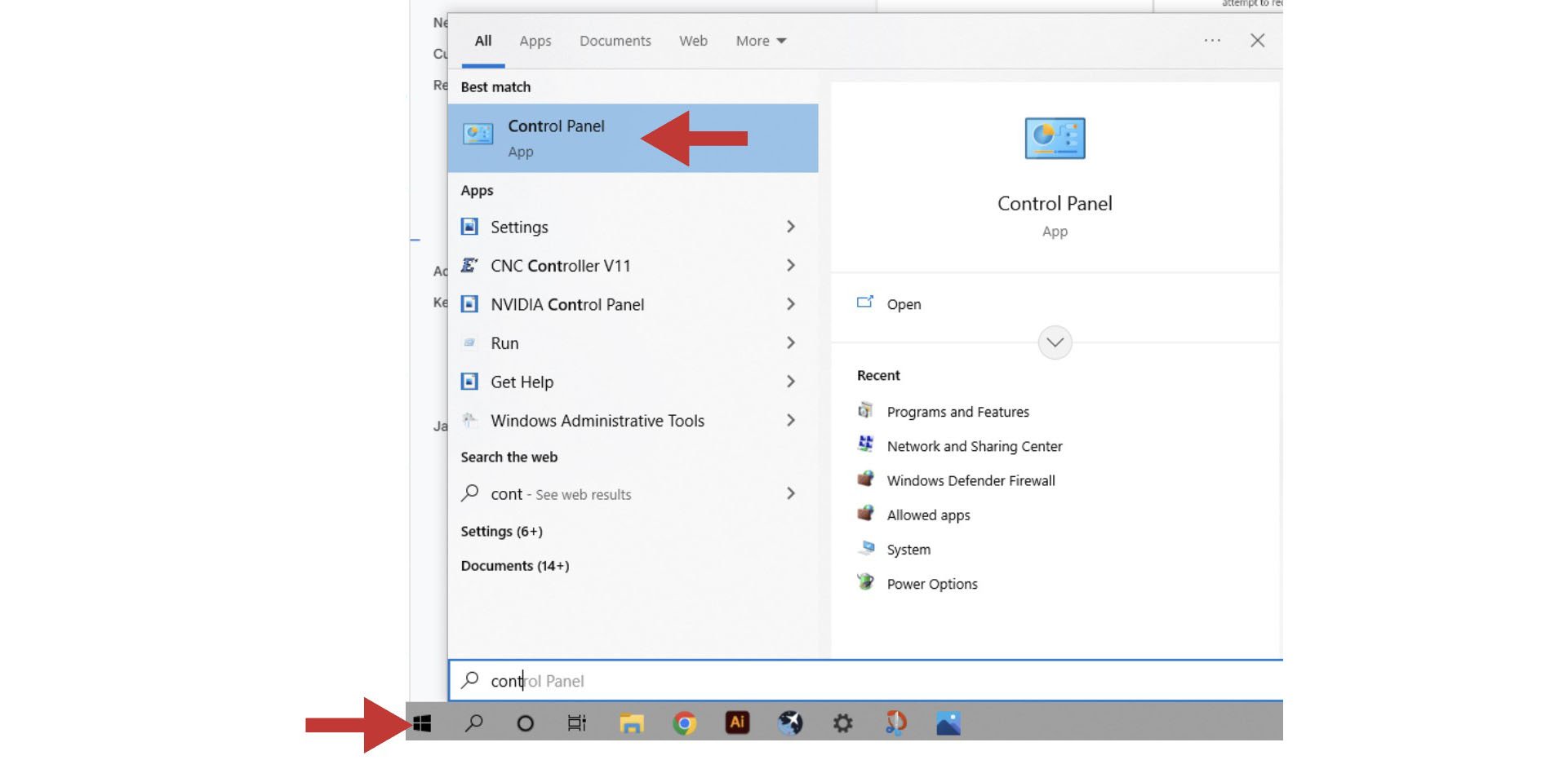
- If you don’t see this popup, click Start and open your computer’s Control Panel
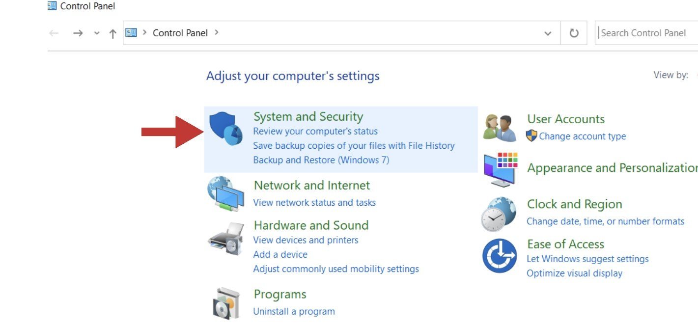
- Open the ‘System and Security’ settings
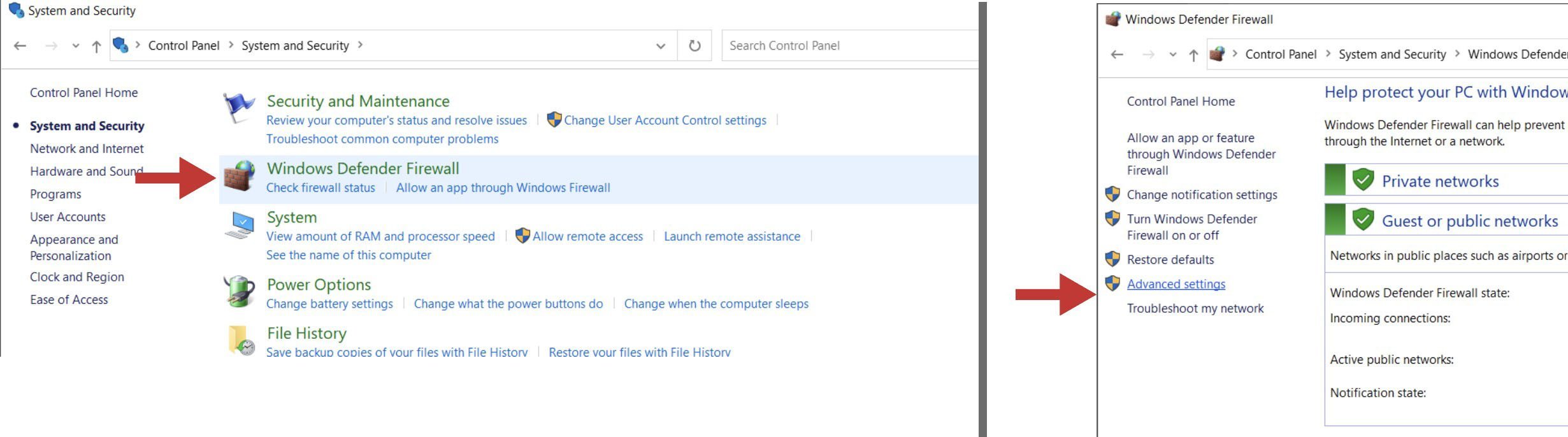
- Open the ‘Windows Defender Firewall’ and go to its ‘Advanced settings’
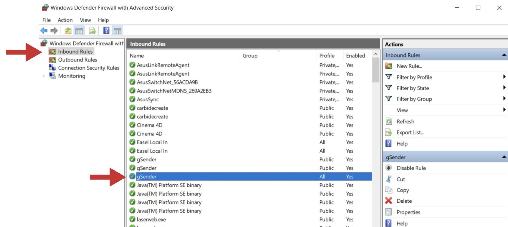
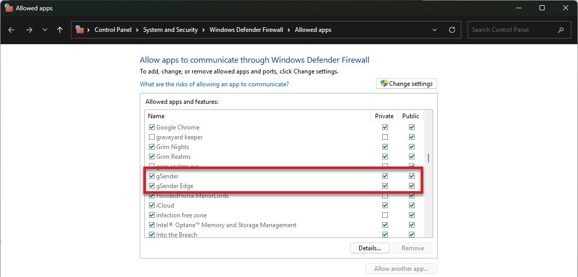
- In the column on the left, click on ‘Inbound Rules’ and then find and double-click on ‘gSender’. There might be three options of gSender to click on, you’ll want to click on the version that has the word “All” under the ‘Profile’ column
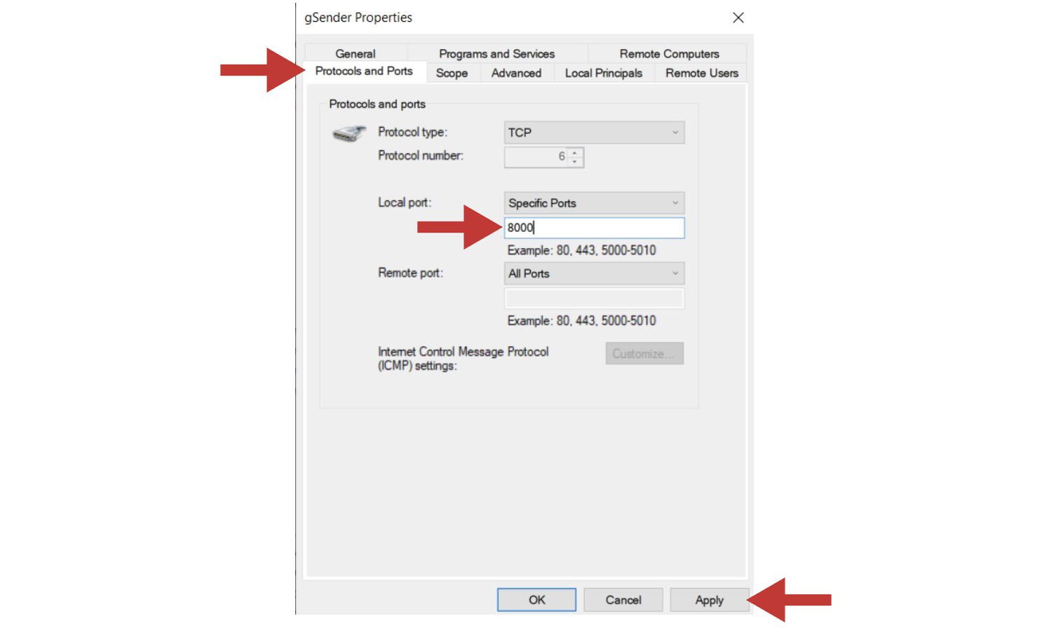
- In the pop-up box, click on the tab labelled ‘Protocols and Ports’. By ‘Local port:’ you’ll want to use the drop-down menu to select “Specific Ports” and then type in the default port of “8000”. If you have added a custom port to gSender’s Shortcut properties, you’ll need to type in that number instead. Once you hit ‘Apply’, you can check to see if this resolved your problem.
- On newer devices you might alternatively need to go to your Windows security tab, and click the Allow an app through firewall text.
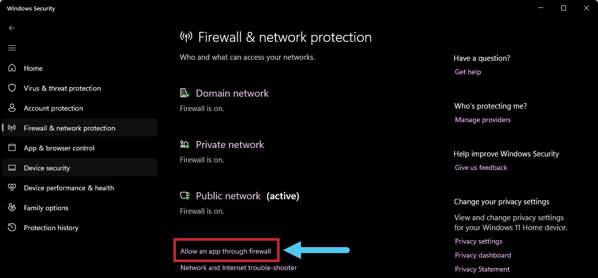
- Scroll down until you see gSender, click on Change Settings, then enable gSender to communicate through the firewall by clicking the checkbox.
- Check the boxes beside “Private networks” and “Public networks” and click the ‘Allow access’ button
- If on Mac, Linux, or Pi you find that you can’t connect with outside devices or just want some extra safety you might want to try opening the Universal FireWall (UFW) on a given port to allow external access. This can be started with
sudo ufw enable(if UFW is not found then install it usingsudo apt-get install ufwand your root password) then opening the desired port, for examplesudo ufw allow 8080opens port 8080 for external access. If you want to see what ports are already open, you can useufw status verbose. - If when gSender reopens you’re met with a white screen, this means an error has occurred that we weren’t able to detect. This is rare, but unless we can find some other way to manage this the only fix is to uninstall gSender and reinstall it again.
Macros
Macros are standalone buttons within the gSender interface that allow you to execute a series of g-code commands when they’re run. Macros can come in handy for a variety of uses:
- Button to run a v-carve or laser engraving of a common insignia into the back of your wood pieces
- Perform a specialized probing function for a particular jig you’ve set up
- Apply a predetermined offset that allows you to easily array your cutting jobs
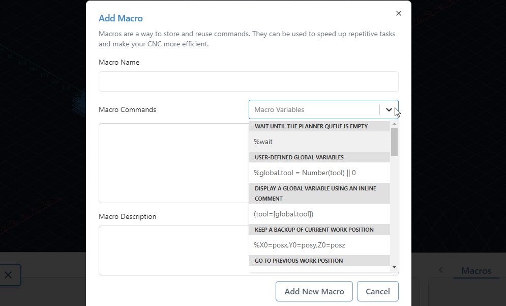
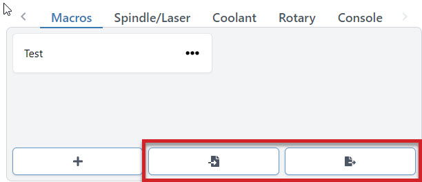
You can create macros using the ‘+’ button under the ‘Macros’ tab.
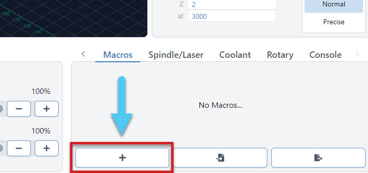
Here you’ll see a space for inputting your custom g-code and adding a name and description for the macro. Advanced users may also want to leverage ‘Macro Variables’ which allow for greater g-code manipulation and pseudo-programming. Press ‘Add New Macro’ when completed.
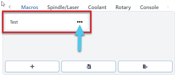
New macros will appear as buttons in the ‘Macro’ tab that can be rearranged by dragging them around. These buttons will display the macro name, show the description if you hover your mouse over them, and can always be later altered or deleted by clicking on their ‘…’ button.
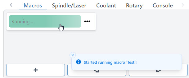
Any macro can be run by pressing it. Once running, you should see the macro start to pulse green while a toast notification on the bottom right hand side of gSender also notifies you that it’s running.
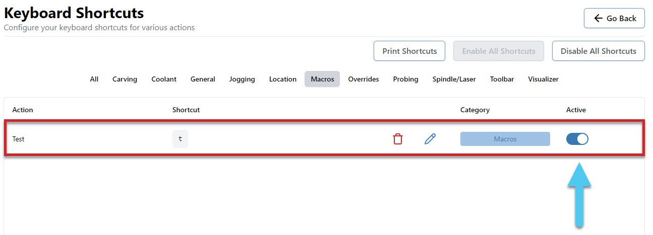
Macros can also be ran using shortcuts. Every time you create a new macro it’ll become available on the shortcuts list for you to assign a key or gamepad button to. Add your keybindings and press the Active toggle to enable the shortcut.
You can share macros with other users or transfer them between computers by using the import and export features. To import one or multiple macros, just press the button on the left and a browsing window will appear so that you can select the macros you wish to import. Similarly, to export all your current macros, press the button on the right and it’ll open a save window, to generate a save file for you.
Advanced Macros
gSenders Macro architecture is based on JavaScript and uses the Esprima library (https://esprima.org/) and so will theoretically support any code that it does. This is exciting because Macros can move far past basic variables if you’d like to perform advanced functions on your CNC:
If you want some initial inspiration, see other macros made by our community or ones made for CNCjs (another g-code sender) which should also work in gSender. Otherwise, here are some other points of guidance:
- You’ll want to develop your understanding of typical g-codes and m-codes that are used for CNC control (the pages linked are very good sources for that)
- The “Macro Variables” dropdown in gSender shows many of the most commonly used operations when making your own macro
- Make your own variable with
%variable = value_you_want_to_set(ex. % probeSpeed = 150) - Use your variable in g-code, like
G21 G91 G0 X[variable](moves the X-axis by the amount set in the variable) - Test your code by printing it to the console
([variable]) - Make dialog boxes appear on the screen to confirm a value or position by putting in an M0 line with a comment, for example
M0 ;Remember to turn on your router before the next stepwhich will pause the macro and give you the option to ‘continue’ or ‘cancel’ - Start experimenting with basic math using numbers and variables like
%combo = (variable + variable2 + 4)/2(Hint: you don’t need square brackets around variable names when the line starts with%, explanation) - Use global variables
global.variableif you want variables that you can use in other macros (note that these get reset once gSender is closed) - Read up on all the other Math features available like absolute value, rounding, and trigonometry (become very useful for more advanced probing cycles for example)
- Start to add more logic to your code using ternary expressions to choose between two outcomes (e.g.
%variable = (30 > 20) ? 10 : 20which is checking if 30 is bigger than 20, and if it is it’ll make the variable = 10, otherwise it’ll make the variable = 20). - Here’s an example of a more advanced macro, made by gSenders Lead Developer, which shows off much of the guidance given above. This macro was made for our new SLB control board in order to cycle between its 3 status light states.
- The macro is only 3 lines. First it checks what the current light state is and sets it to 0 if it doesn’t have a state. Next, it sets the lights to the current state but applies a modulus of 3 since we can only have a state value of 0, 1, or 2 so we’ll get an error if the value is 3 or above. Lastly, it adds +1 to the state so that if the macro is run again it’ll put the lights into a new state.
%nextLight = global.lightState || 0M356 P0 Q[nextLight % 3]%global.lightState = Number(nextLight) + 1
- Store many variables in an array so that those variables can be used in other macros without assigning them all as global
%setup = {}%setup.this = 0%setup.that = 1%global.setup = setup- then in the other macro
%setup = global.setup
- Create functions that you can then call later such as
%rapid = function (x, y) {return 'G53 G90 G0 X' + x + ' Y' + y + 'n'}then later run it with[rapid(x, y)] - Read more about the Esprima library here: https://docs.esprima.org/en/latest/syntactic-analysis.html
Community Macros
If you’d like to add your own macros to this page, edit the page on GitHub and use the template below for each macro.
Disclaimer! These Macros are submitted by our community. They aren’t vetted by us and might cause damage to your machine so use them at your own risk! Please review the code and test it before assuming it will work with your machine setup.
Console
The console is a tab that you can access at the bottom right hand side of the gSender window. The text here shows a truer representation of the communication that happens between your computer and your CNC. As you start to understand more about your machine, this is a great tab to reference so you can see if commands are being properly sent, received, and executed. It’s also great for troubleshooting since you can:
- Manually send g-code commands to your CNC
- Check for errors or alarms and the g-code that caused them (normally the line that comes before)
- Copy text straight from the console to send in an email for help by clicking the ‘…’ button next to ‘Run’, then clicking ‘Copy last 50 lines’.
- Even open the console in another window by pressing the top, right icon to help you see more console text at a time (if you press the button again once you reconnect to your CNC, it’ll reconnect the console stream to the original window too)
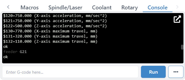
When you first start up gSender, the console will display EEPROM settings that are sent from the Arduino in the control box. These EEPROM settings control parameters for your CNC such as:
- Maximum speed and acceleration in each axis
- Boundaries of the work area
- Direction of each axis movement
- Limit switch settings
To access EEPROM settings again, enter in “$$” into the console and hit the ‘Enter’ key or click the ‘Run’ button. These settings can be changed via the console as well as the Firmware Tool which we’ve designed as a much more visual way to alter machine settings.
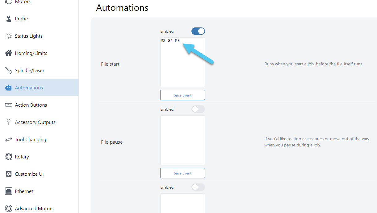
Automations
A powerful feature to control your accessories automatically (like turning on/off a spindle or vacuum) or to run movement macros that are custom to your machine. ‘Program Events’ (formerly “Start/Stop G-code”)’ in gSenders settings automatically apply g-code to your cutting job at the start, end, or if you stop, pause, or resume the job. The ‘Stop’ event is there to ensure that “ending g-code” is always run even if you have to stop a job prematurely. You can also toggle these on and off if you don’t want them run for specific jobs.
Three massive perks to setting up automations this way are:
- There’s no need to get into the weeds customizing your CAM post processor
- gSender is able to send code when you pause, resume, or emergency stop your machine, all of which a g-code file on its own would never be able to do
- This additional amount of control will make your CNC safer to use
For example, if you were to add M3/M5 commands to your CAM post processor to control your spindle but then chose to pause your job midway to check something, then most CNCs wouldn’t know to stop spinning your spindle or retract it since g-code files can’t carry this information; this is where gSender is able to the heavy lifting.
For the text-box of the situation you want the action to happen, type in the g-code commands you wish to run, then press the ‘Update‘ button to save it. For example, if you installed an IOT relay to turn your router and vacuum on and off and wanted to make sure they were enabled for every job you ran, you could add:
- “M8” for Start and Resume
- “M9” for Stop and Pause
- If you wanted to add a delay to give your vacuum or router time to fully turn on, then you could add “G4 P5” after the M8 for a delay of 5 seconds (you can customize that delay to your equipment)
- If you wanted to keep the vacuum and router running during a pause, then you don’t need to add “M9” to Pause
- All this can also apply to automatically control a spindle, where you’d instead use “M3” and “M5“, you can also add a delay with “G4 P#“
- If you want to raise the Z-axis on Pause and lower it on Resume, you could also add:
- “%global.move=modal.distance” then “G91 G0 Z-5” for Pause to move 5mm out of the way
- “G91 G0 Z5” then “[global.move]” for Resume to move back down
Tool Changing
For CNC machines, tool changes are pauses that are programmed in the g-code for a user to switch out the cutting tool for a different one, or the machine to do that automatically. The workflow can also sometimes involve pausing until the user tells it to continue, usually through a ‘Resume’ and/or ‘Confirm Tool Change’ button on the machine interface. This allows you to run multiple toolpaths (cutting operations) within one g-code file.
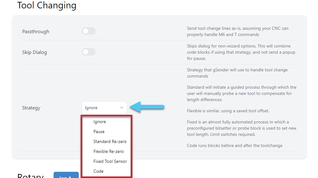
The g-code for tool changing is an M6 command. gSender is quite capable when it comes to customizing CNCs for tool changing, even having full Wizards built-in. The tool change options are in Config ➜ Tool Changing. You can select from one of 6 different options, and even choose to ‘passthrough’ the M6 and T commands to the CNC controller for CNCs that are capable of handling tool changes on their own.
You can Ignore any M6 tool change commands, Pause the job when a tool change is recognized, or select one of the Wizards that will guide you through pre-set tool changing methods. In the image below, you can see an example of the Helper window opening up to show the Standard Re-zero Wizard with all of its guided steps.
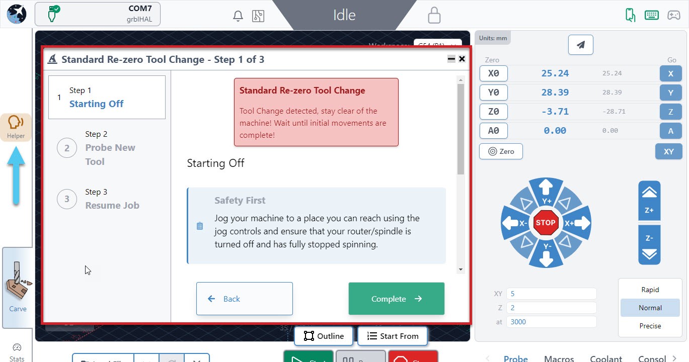
If you are using one of the wizard options, know that you can access all other gSender controls while the wizard is open like jogging and zeroing. It also has flexibility to go back a step if you missed something or had a mistake, or to be minimized temporarily if you want to check the visualizer.
- Ignore
This simply ignores any M6 commands in the g-code file. This is the default option since it’s perfect for beginners that only make projects with one tool or those that create separate files for each tool and prefer to manually perform tool changes between files. - Pause
Pauses gSender at the tool change point, as if you had hit the pause button manually. This gives you freedom to jog, zero, or anything else you’d like, and is great for those that are running multi-tool files but want to use a different process than the Wizards provide. This could be a manual probing process, a different tool changing approach, or running custom macros to support your machines specific hardware. gSender is compatible with tool length sensors like the Carbide 3D bitsetter, and our community has compiled a list of macros for tool changing that you can use when you are paused. Just note that pausing can’t always guarantee keeping track of your movements and actions when it comes time to resume the job so try to ensure you get back to the starting point and set zeros correctly. - Standard Re-zero (Wizard)
Titled ‘standard’ because it’s exactly the same as the standard process you might normally follow for running a file, changing the tool, re-zeroing Z, then running the next file except it’s applied to a single file with multiple toolpaths. Since the process is so familiar, this is a great way to dip your toes into tool changing within one file. Compatible with using a touch plate or the paper method, zero out at a predetermined spot (usually at the front left corner), and use jogging to move around. The advantage of introducing this extra automation and guidance during tool changes is that you don’t have to worry about custom macros and it reminds you of simple steps like turning the router back on or zeroing Z. - Flexible Re-zero (Wizard)
Similar to the ‘standard’ wizard with similar steps and manual movements but provides the ability to zero Z off a point that wasn’t your starting Z when it comes time to change the tool. This is useful if you tend to carve away your material and lose the starting Z or you don’t have limit switches but would like a process similar to a tool length sensor. - Fixed Tool Sensor (Wizard)
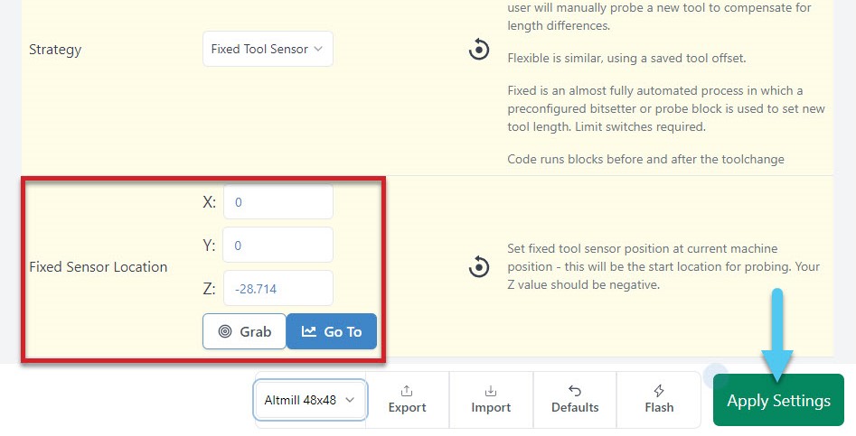
This is the most automated setting where all probes and movements are done for you, you only need to intervene by changing the tools. Set up the job and zero normally then expect the machine to move to the sensor location when it reaches a tool change, verify tool length, prompt for a change, probe new tool, then resume cutting. Your machine will need to be homed, have limit switches, and have a tool length sensor (compatible with Carbide 3D bitsetter for example) in order for this option to work. To set up the sensor mount the router/spindle as far down as you might typically put it, with the longest bit mounted in it, then jog it to hover over the tool length sensor with some room to spare and open Config ➜ Tool Changing to Grab that location, then apply the new settings. This will be the spot your machine moves to every tool change so if it’s too low or your sensor doesn’t work it’ll run into the sensor. You can also enter these coordinates manually, and test them with the Go To button.
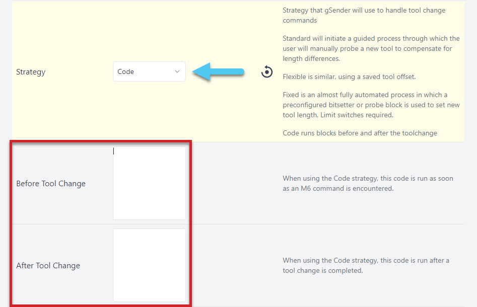
- Code
You can enter your own macros before and after the tool change with this strategy selected which is fairly powerful for making tool changing processes that are more automated than just pausing.
You can also learn more about how some of this works by checking out this user-made video by SparksTech!
Rotary / 4th-axis
gSender has a unique ability to control a rotary axis on normal, 3-axis grbl and grblHAL machines which we call “rotary mode”, as well as typical 4-axis rotary setups on grblHAL machines. The difference between these two is just a matter of how you set it up and whether your machine has enough unique drivers to control either 3 or 4 unique axes.
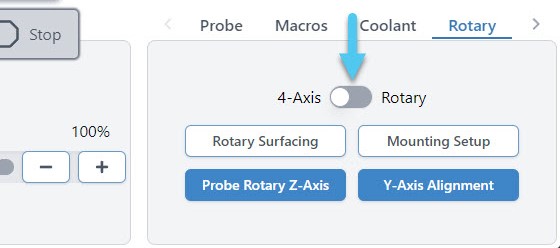
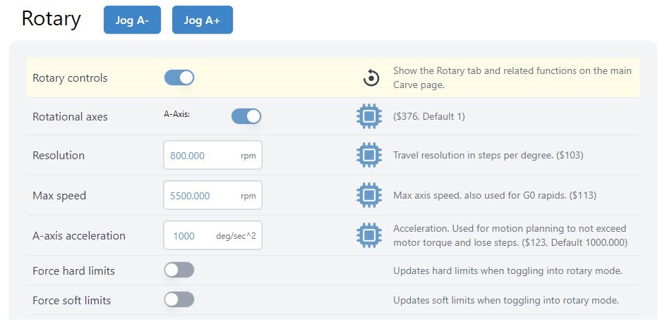
In either case, the setup starts by going to Config ➜ Rotary and enabling the rotary controls. Don’t forget to hit the ‘Apply Settings’ button!
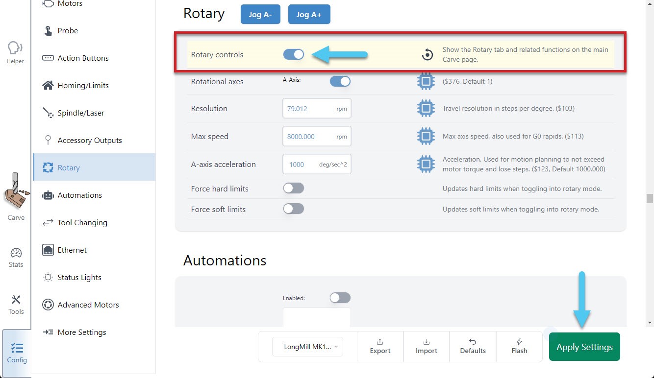
Once done, you will see an additional tab at the bottom right of the main Carve screen, called ‘Rotary’. For 4-axis setups, you’ll immediately have access to all buttons and it’s unlikely that you’d want to switch over to ‘rotary mode’, meanwhile for 3-axis setups you’ll notice that some buttons will be grayed out before you’ve switched to rotary mode, or once you’re in rotary mode. This is because some actions require movement in the Y-axis and others require movement in the A-axis, and since you have a 3-axis machine you can only do one or the other at a time:
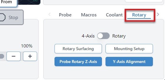
- Rotary Toggle – for toggling between Rotary Mode and 4-axis Mode, or if you’re using a 3-axis machine the only option will be rotary mode
- Rotary Surfacing – an easy tool for turning square stock into round stock
- Mounting Setup (Vortex-specific) – helps to drill holes into your wasteboard to mount the Vortex track to your CNC
- Probe Rotary Z-axis – automatically probe to find the Z-axis zero
- Y-axis Alignment – automatically probe to align the Y-axis to the center of the A-axis
Note: you’ll always want to first mount (Mounting Setup) and align (Y-Axis Alignment) your rotary axis before moving forward with any of the other features like: switching to rotary mode, using the jog controls, rotary surfacing, or any other rotary actions.
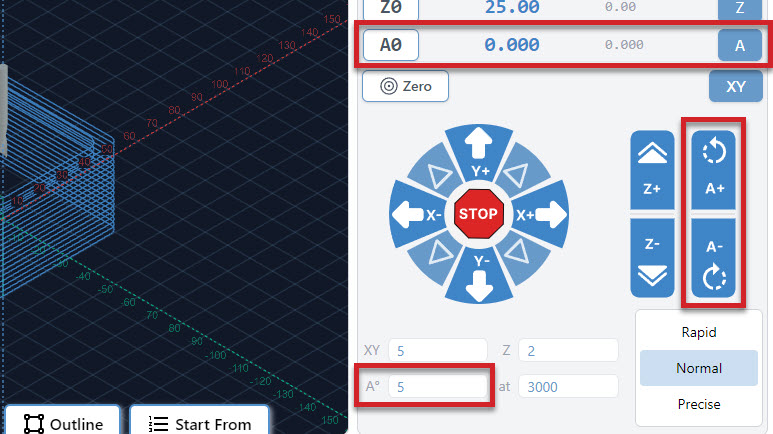
- Jog Control – You’ll also see new options to rotate the A-axis, go to Zero, set Zero, and adjust speeds
Mounting Setup
When mounting a rotary axis, it’s important to be parallel to the X-axis, and helpful to have a repeatable position so you can reliably mount and unmount the rotary, depending on when you want to use it. If you have your own rotary axis, this is a step that you’ll have to do yourself.
For those who might have our Vortex rotary axis, the ‘Rotary Mounting Setup‘ button is a specific macro that cuts into the machine wasteboard to help you fasten the rotary with perfect parallel alignment. Check out our Vortex Resources for more details on how to use this wizard.
Y-axis Alignment
When switching from regular CNC use to Rotary Mode, you will probe to align the Y-axis along the A-axis. You can do this in the Rotary Tab by hitting the Y-axis Alignment button. Check out our Vortex Resources for more information on aligning your Y-axis when setting up your Vortex.
Rotary Mode Toggle
Moreso meant for 3-axis machines, this toggle can only happen once you’ve got your rotary axis set up properly, because after switching it’ll assume you’ve changed your motor wiring to be connected to your A-axis instead of your Y-axis.
The idea is that once you’re in this “rotary mode”, gSender does the legwork to swap firmware settings over to your rotary setup, translate A-axis movements to your machine as if they were Y-axis movements, and as long as you’ve done the alignment and swapped over your wires then your rotary A-axis should now be good to go!
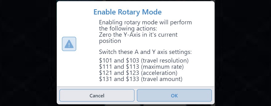
When you enable Rotary Mode, you will see a popup warning you of the changes that will be made by continuing:
- The current position of your Y-axis will be set to Zero
- Your hard limits may be turned off
- Other firmware values might get updated to suit your rotary
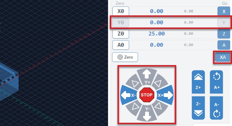
Once enabled, you will see a confirmation appear in the bottom right corner and several changes will happen in gSender:
- The Mounting Setup and Y-axis Alignment buttons will become grayed out
- The Rotary Surfacing and Probe Rotary Z-axis buttons will become available
- The Go buttons for the Y and Z-axes will become grayed out
- The Y0 button will become grayed out
- The ‘XY‘ Go button will be changed to ‘XA‘
- The Y-axis jogging buttons will become grayed out
Rotary Probing
In a similar fashion to regular cnc machining where you set a zero position in relation to the stock you are using, we will do the same when rotary carving. Two differences are that we don’t need to enter a tool diameter and each axis will be set separately.
Setting Z-axis
You can set your Z-axis to either the rotating axis center, or the surface of your stock in a similar fashion to regular CNCing. We recommend using the axis center, as that allows you to make use of the Vortex’s built in Z-axis probing functionality.
To do this, jog the cutting bit to be hovering approximately ~15mm just above the chuck. Double check that your probing wires are in place before proceeding!
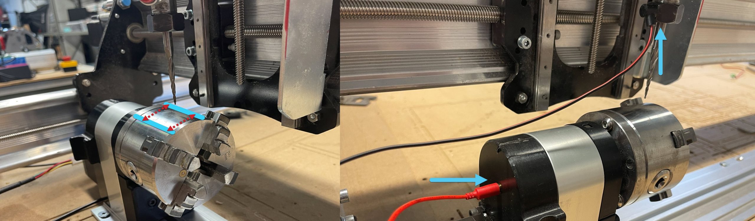
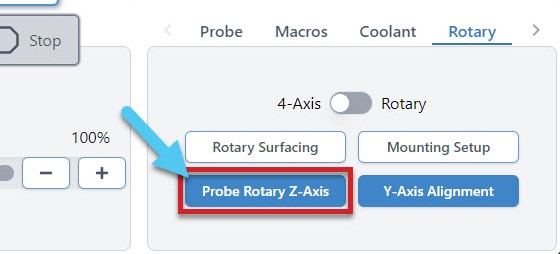
In gSender, select the rotary axis tab, then click ‘Probe Rotary Z-axis‘ and the Z-axis will begin probing automatically, setting the Z-zero point for you. This will need to be done for each tool change in addition to the beginning of each job.
Setting X & A-axis
Setting both the X-axis and the A-axis are done manually.
- To set your X-axis, jog to wherever you’d like the job to start then click ‘X0‘ to set your X-zero point. Make sure this is far enough from the chuck to ensure there won’t be any collisions with your cutting bit, workholding or screws.
- To set your A-axis, simply click ‘A0‘ at the beginning of each job, under the Rotary Jog Controls. Note that if this isn’t done, the rotary will spin back to zero before the job starts.
Rotary Surfacing tool
he Rotary Surfacing button will allow you to turn square stock down to a cylinder. We recommend using a ¼ inch upcut end mill for turning stock, as it’s the most efficient.
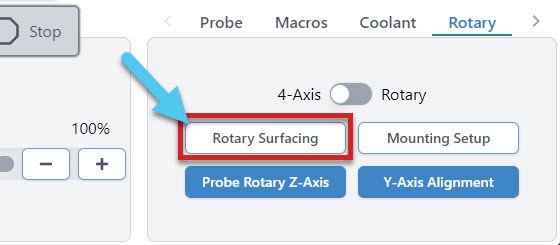
Now you will see the Rotary Surfacing Tool. Here you will enter details about your stock length, start and final dimensions. You will also see spots for Bit Diameter, Step over, Spindle RPM, and Feed rate.
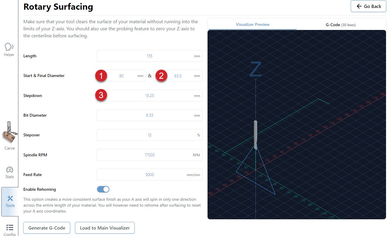
Rotary surfacing is similar to the regular XYZ surfacing tool. Let’s explore this a bit further.
- Your start diameter is the largest diameter on your stock. Usually this means the diagonal distance from opposite corners if you’re starting with square or rectangular stock.

- Your final diameter is determined by the short side of your stock.
- With a starting height of 90mm and a finished height of 63.5mm, we are removing 26.5mm of material. However, since we have the Z-axis set at the center of the material, we will need to divide that 26.5mm in half. We are basically taking 13.25mm off of the top and the bottom. If you want a single pass, your step down would be 13.25mm. Dividing that by two and setting the step down to 6.625mm, means that we will be doing two passes. This will produce a piece of round stock with the maximum diameter possible.
(Start Height – Finishing Height) / 2 = Total Step down for ONE pass
Rotary Settings
When you go to Config ➜ Rotary, you’ll be able to enter your own settings, reset the default settings and turn Hard Limits on/off.
More
There’s always more to learn about gSender including many videos of lesser-known tips, setups on different CNCs, and open source modifications people have made. For example, check out these videos of Chris showing off some common and less-common tips about how to improve your gSender experience!