
This document is the “SLB/SLB-EXT bible” for any of the answers you might be looking for when setting up your new controller. This includes sections on all the features, their pinouts, associated settings, and other things you should know when installing the controller onto your CNC.


You’ll find that the SLB/SLB-EXT builds a lot from our original LongBoard while maintaining a lot of the familiar behaviour and features. If you are interested, brush up on the original LongBoard documentation here.
Features List
Comparing the SLB/SLB-EXT to our original LongBoard and to other controllers on the market, some of the main advantages you might notice:
- Be confident in your CNC completing jobs in a variety of environments. Vastly improved reliability and immunity against EMI with better board wiring, protective components, onboard ferrite improved USB protocol, processor capability, larger buffer, and Ethernet as a communication alternative
- Faster CNC speeds and less motor noise by using more efficient motor drivers (SLB only)
- Safer E-stop informs machine when an emergency has happened and de-powers all accessories
- Detachable E-stop gives you something to reach for if your CNC starts going where you didn’t expect
- RGB CNC status lights visible from a distance to always know what your CNC is up to or if something’s gone wrong. Light onboard plus support for external RGB strips to set up as you wish: under your X-axis rail, a router/spindle ring light
- 3 programmable buttons for you to customize your CNC to your workflow
- Live overrides to fine-tune your feeds & speeds on the fly when running a job
- Supports inductive sensors and mechanical switches for far more accurate and repeatable CNC positioning for job recovery or multi-day runs than using stall homing in a dirty CNC environment
- Individual axis holding current, allows you to hold just the Z-axis from falling with a heavy spindle without having to keep all other motors powered too (SLB only)
- Added support for an independent Tool Length Sensor (TLS) for tool changes
- Control spindles/VFDs and other accessories with Modbus over RS485
- Independent 4th/rotary axis output to an external driver for simultaneous 4-axis cutting
- More customizable IO to fine-tune your at-home or shop CNC setup
- Powered by HAL, leaving bandwidth for even more features to be added with future firmware updates
- Don’t have to pay extra for a built-in computer, instead choose to run something lightweight you already have on hand, or a more powerful setup to combine both design and CNC control from one computer in your shop
Dimensions
The SLB/SLB-EXT is a typical PCB with a roughly 210 x 100 x 20mm (8.3x4x0.8″) footprint, not including plug stick-out on the short ends. It’s designed to either fit inside its enclosure, accommodate up to 4mm of edge mounting on the long side, or mount via standoffs.


The enclosure has a rough size of 215 x 112 x 50mm (8.5×4.4×2″) not including the 16mm (0.63″) flanges on the short ends. These flanges allow it to be mounted to any flat surface either horizontally or vertically as pictured. The backside of the enclosure also has a slotted feature to fit a bracket or directly mount using T-nuts.
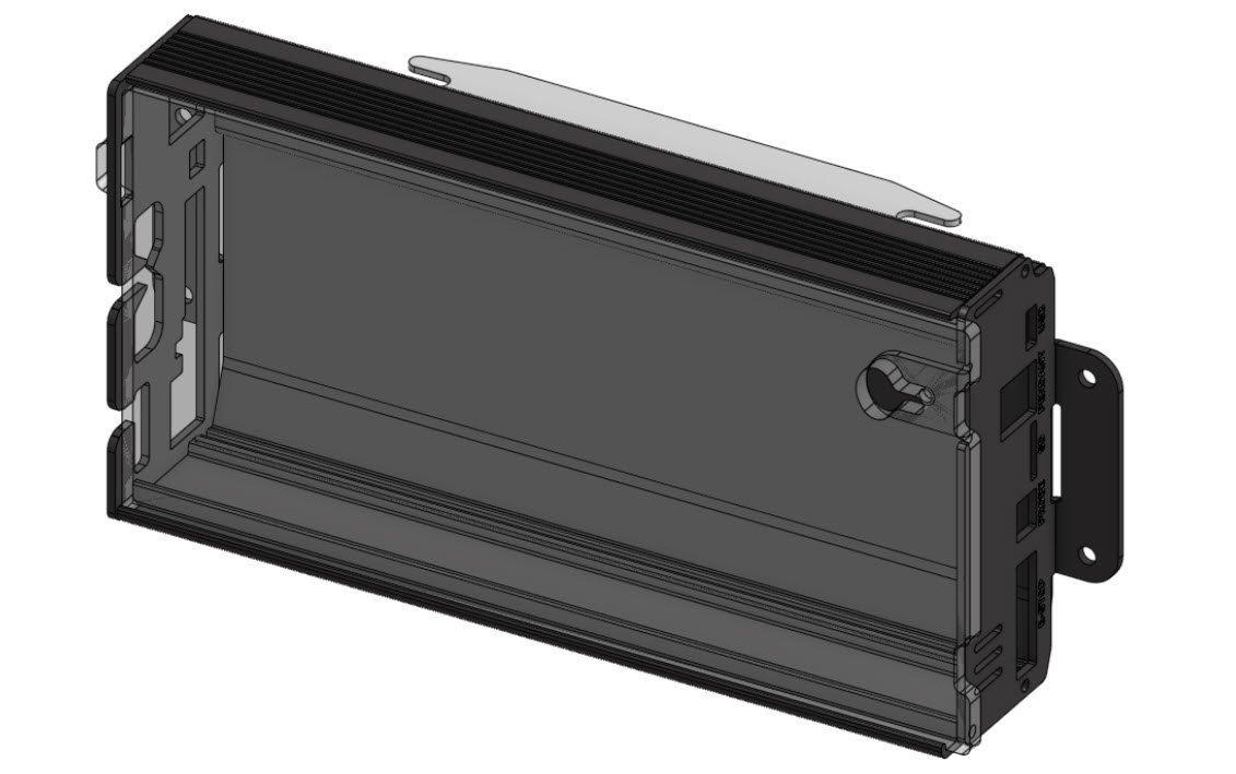
The enclosure has been designed with reasonable consideration for dust penetration, but feel free to mount the box further away from your CNC, minding wire length. When mounting the controller on its own or among other CNC control electronics, consider that most wires are designed to route out the backside of the enclosure, with the exception of a few more typically accessible plugs on its front, like the E-stop and USB-C. For more information see the section on Enclosure Mounting.
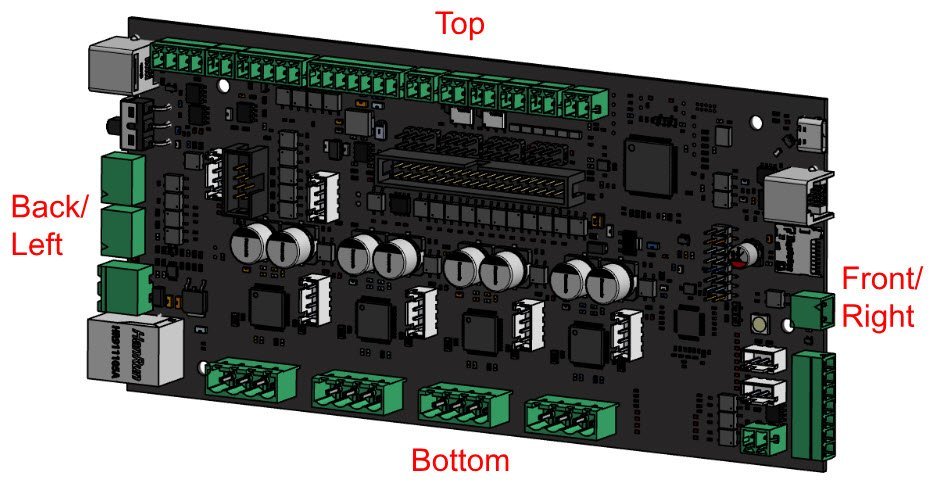
Note: for the rest of the docs the typical naming orientation for the controller is shown below
Software
Firmware
The controller runs grblHAL, which may look similar in name to grbl but it is a completely new approach to CNC control. Your board will ship with the latest version of firmware already installed, but we’ll occasionally release updates for new features, functionality, or bug fixes. For more information on this process, go to the Firmware Flashing page.
Open Source
This project has no patents, we make everything available to the public just like much of the rest of Sienci Labs’ projects. As we start to roll out the SLB/SLB-EXT into production, we’ll post our source files for our custom grblHAL plugins, the SuperLongBoard PCB design, enclosure design, and any other relevant manufacturing and sourcing info we can think of. We’ll also make sure we’re clear on the licenses for use.
Wiring
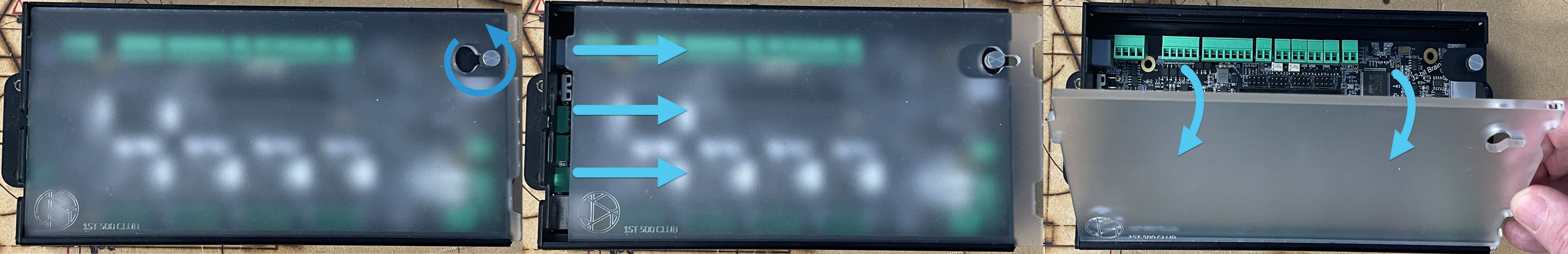
You may need to remove the cover to access some of the connectors inside. To remove the cover, unscrew the top-right thumbscrew a couple turns (pictured) then slide the cover to the right. Once the hole in the cover lines up, pull the top of the cover towards you and it will come free.
Route all the wires from inside the enclosure through the two openings at the back, then close the lid again. The smaller, bottom one is meant to snugly fit all the motor cables, while the remaining cables should all fit into the larger, upper opening.
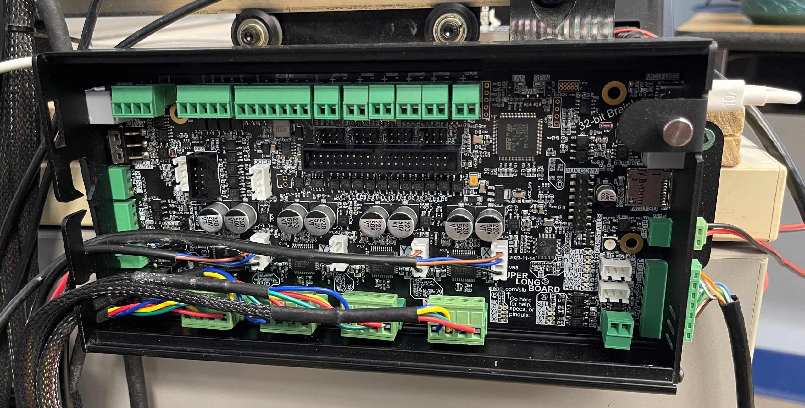
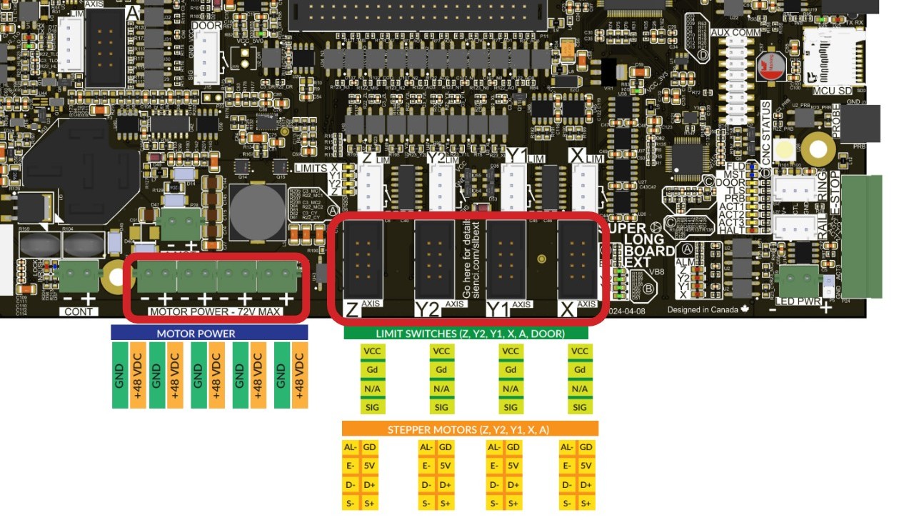
Here’s a general wiring ‘map’ you can use as a reference to start hooking things up. It covers the full scope of plugs and features that the SLB/SLB-EXT currently supports. Go here for the full list of connectors.
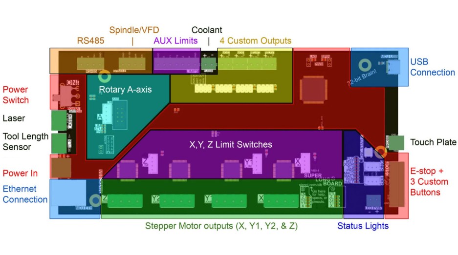
| Power & E-stop | Power in and control via switch, E-stop, E-stop backup, and board reset |
| USB & Ethernet | Communication ‘streaming’ to the SLB |
| Motors | Typical 3 axis (ganged Y) bipolar stepper motor control |
| Touch Plate/Probe | Supports touch plates or other surface probing |
| Status Lights | Onboard CNC status light, RGB LED strip outputs, other diagnostics lights |
| Limit Switches | Hookup for Homing/Limits with two plug styles, also supports min/max switches for hard limits |
| Laser | 5V PWM dedicated output for independent Laser control |
| Action Buttons | 3 programmable action buttons that support macros |
| Accessory Outputs | 2 SWITCH outputs that turn on any external circuits 1-24V up to 1A, and 2 AUX POWER outputs which provide up to 24V 250mA to external accessories |
| Spindle/RS485 | Controls a Spindle or VFD using 5V PWM or RS485 |
| Tool Length Sensor | Powered input for a Tool Length Sensor for tool changing or for use as a secondary probe |
| Rotary/4th/A-Axis | Output signals for an external motor driver and input of an independent rotary axis limit switch |
Power & E-stop
Power Supply Specifications
The SLB needs a 24V 10A power supply to run all stepper motors at rated current alongside the other onboard accessories.
The SLB-EXT needs a 48V 12.5A power supply to run all stepper motors at rated current alongside the other onboard accessories. This board can also support 36V power, should that be necessary.
E-stop
Each SLB/SLB-EXT comes with an E-stop and pre-made wiring to keep you safe out-of-the-box when cutting. When pressed, the E-stop is designed to cut all power to the stepper motors and also send a signal back to the MCU to disable other accessories that your SLB/SLB-EXT controls. This includes turning off the spindle, IOT Relay, and anything else that’s triggered by M3/4 and M7/8 commands. Use the E-stop when there’s a hazard during carving and you need to immediately stop the machine.
Inputs and Outputs

-
The larger 2-pin plug on the left side is the power connection where you’d plug in the power supply
-
There’s a main power switch above it to switch main power to the whole board
-
The 7-pin plug is for the E-stop and its customizable action buttons
-
For troubleshooting, there’s also:
- E-stop pin on the bottom left to act as an override if the main E-stop switch is broken
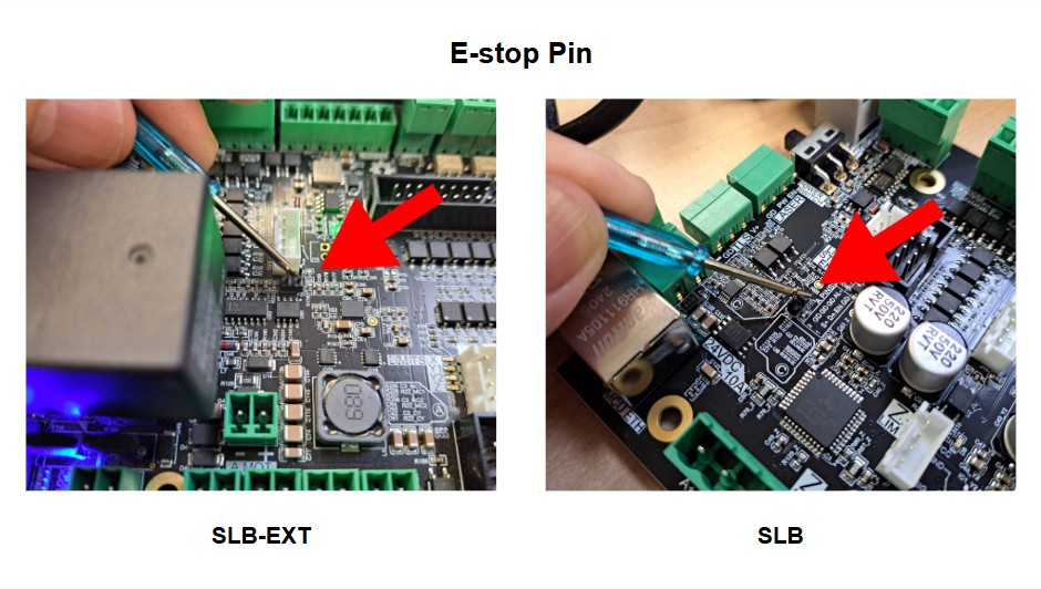
- Reset pin on the top right to quickly power-cycle the board
Power & E-stop Guidelines
-
Keep the power switch OFF (slide it UP to be in the OFF position) whenever you plug or unplug the power cable.
-
Make sure the polarity of the power supply connector is correct before plugging it in (red/+ on top and black/- on the bottom).
-
There is a safety feature to ensure that if the controller loses power, the machine will not automatically be on when power is restored. When you power ON the controller, press then twist the E-stop clockwise to unlock the controller.
-
If you suspect your E-stop isn’t working, check our E-stop troubleshooting steps.
-
If you want to set up the custom action buttons for your E-stop, jump forward to the Action Buttons section 🙂
USB & Ethernet
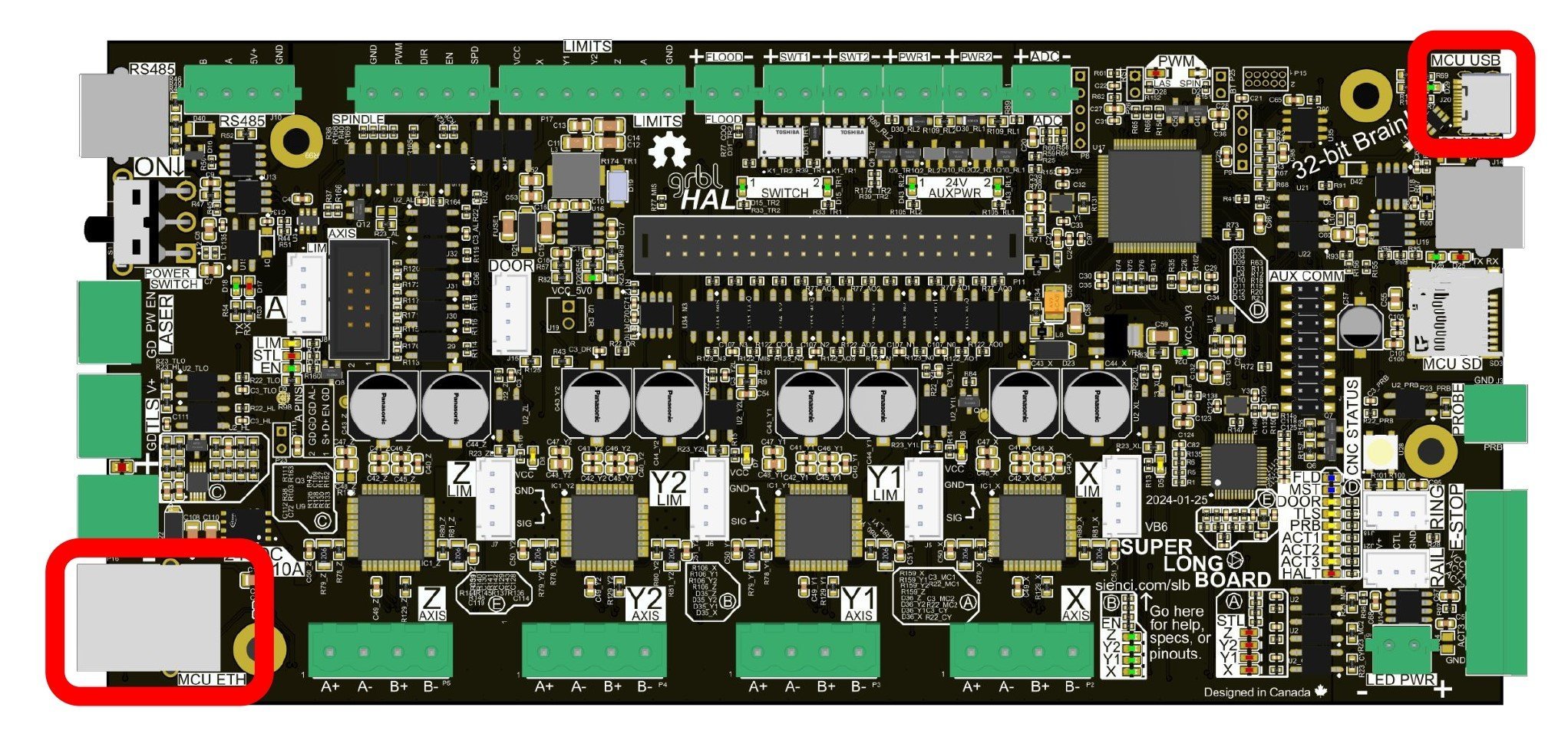
The SLB/SLB-EXT offers USB-C as well as Ethernet as a way to connect your CNC to your computer. Both are isolated for noise, with larger data buffers, and should provide a very reliable connection. We worked hard on a robust USB interface with far more data checks and signal isolation to match a typical Ethernet setup, though Ethernet still has some inherent reliabilities that will always make it more robust. This means you can use either, but USB-C is more beginner friendly and is needed to perform the initial board setup. If you want to place your computer further away from your machine or you are seeing disconnection issues, then we’d recommend switching over to Ethernet. However the controller’s STM32 chip isn’t capable of supporting firmware flashing over Ethernet so keep the USB-C cable handy if you need to do any future updates or recover from a board reset.
The SLB/SLB-EXT needs to be powered and turned on for you to be able to make any USB or Ethernet connection.
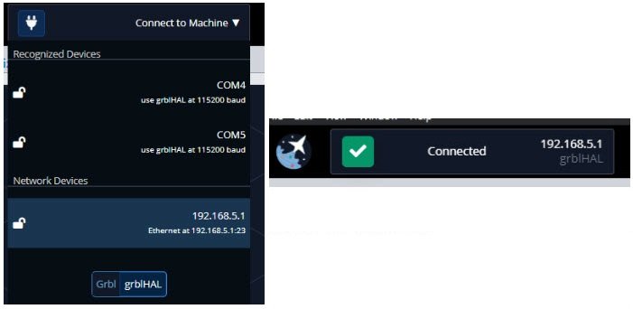
To connect over USB, plug the cable into the front of the control box and into an available USB port on your computer, then connect on gSender. Ensure that the USB cable you use is capable of data transfer and not just charging.

To connect over Ethernet, you’ll need:
- An Ethernet cable
- A g-code sender that can connect to CNCs over a network, like gSender or ioSender
- A device with a free Ethernet port that can also run the g-code sender
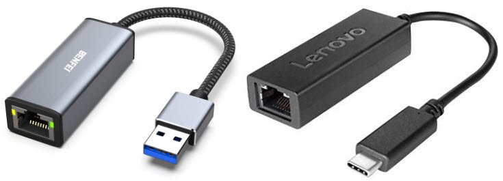
- If your computer only has one Ethernet port and it’s already used, you can try picking up a USB to Ethernet dongle or adding an additional Ethernet card. You don’t need anything fancy since the controller only needs 1-2 Mbps of bandwidth to run. If you use the dongle, the USB side will plug into your computer, and the Ethernet side will connect an Ethernet cable that you’ll run to the controller.
Keep in mind that setting up Ethernet is a bit more involved, and we recommend direct Ethernet communication from a computer to the controller; not sending over a network.
Ethernet on Windows
Current
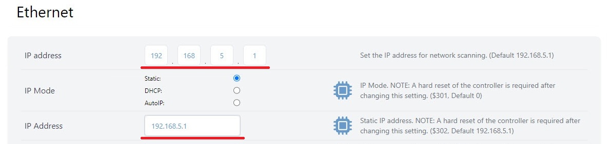
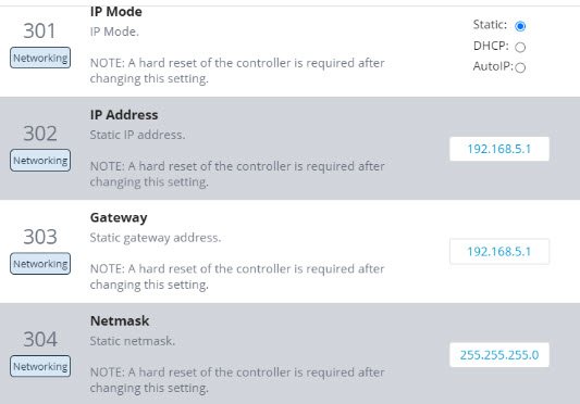
- To start, connect to your CNC over USB, open the Config tab to the Ethernet section, and copy down the numbers you see for the ‘IP address‘ and ‘Netmask‘. The defaults should be
192.168.5.1and255.255.255.0respectively, with the IP mode set tostatic.
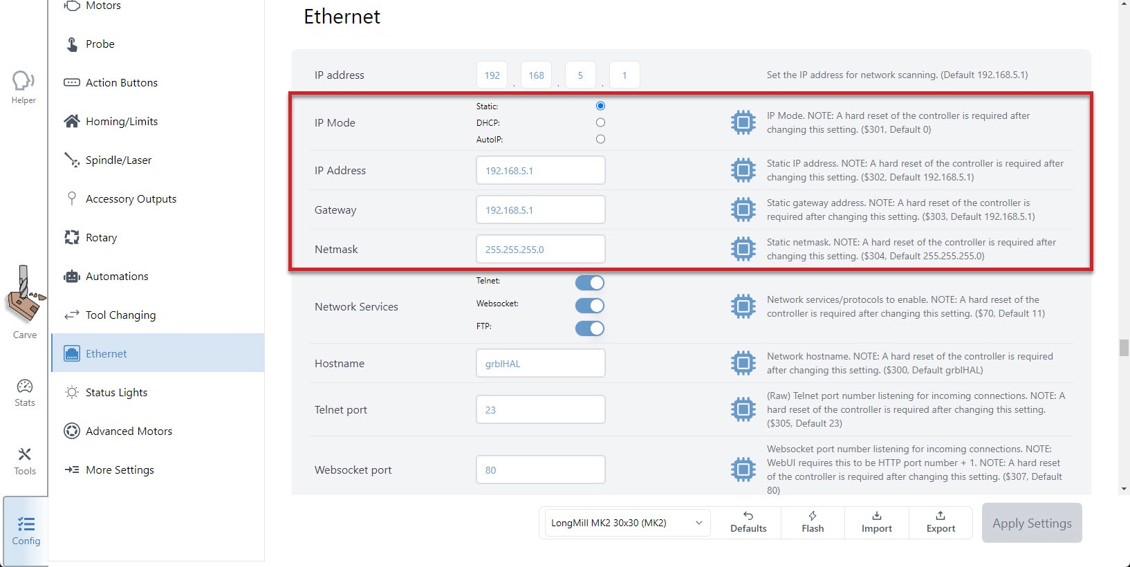
- Once copied down, you can unplug your USB and connect the Ethernet cable directly from your PC to your board. If you look where you plugged the Ethernet cable into the controller from the outside, you should see a green light on and a flickering yellow light.
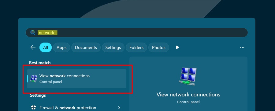
- Now you’ll need to configure the PC’s Ethernet interface. Start by opening the Windows menu, searching for “network” and click ‘View network connections‘ to get a list of Ethernet ports.
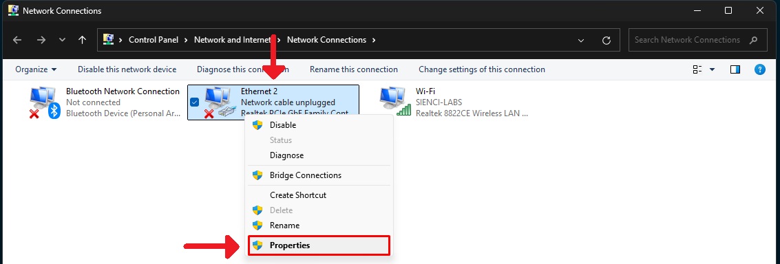
- Here you should be able to find the ‘Ethernet‘ listed that you connected to your SLB/SLB-EXT. Even if there are multiple Ethernet options, unplugging and re-plugging the cable from the SLB/SLB-EXT will show which one it is. Once you know, right-click it and open its ‘Properties‘.
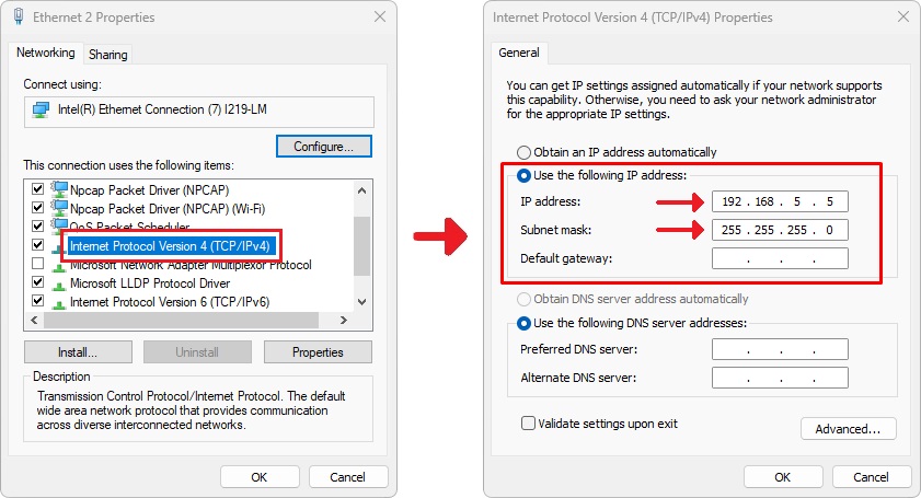
- In the Properties, find the option for ‘Internet Protocol Version 4 (TCP/IPv4)‘ and double-click it. Here, you’ll want to:
- Select the ‘Use the following IP address‘ option
- Type into ‘Subnet mask‘ the ‘Netmask’ number you copied down
- Type in the ‘IP address‘ that you copied down, just change the last number (for example, change it from
192.168.5.1to192.168.5.5) - Click ‘OK‘ to save and close the options
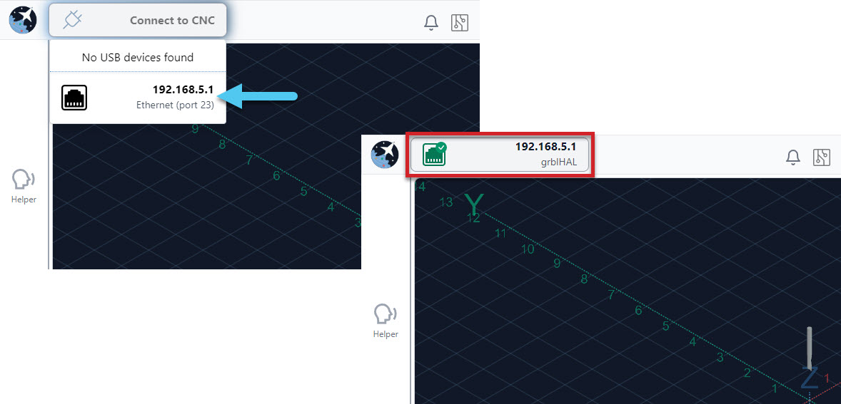
- Back in gSenders Config tab ➜ Ethernet section, make sure the IP address for gSender matches the IP address from the firmware.
- Now click on Connect to CNC, choose the Ethernet Port option and you should see it connect successfully 🙂
- If you have a problem connecting with Ethernet, go back over the setup steps. You can also reconnect over USB to double-check your SLB/SLB-EXT Ethernet settings.
Classic gSender
- To start, connect to your CNC over USB, open the Config tab to the Ethernet section, and copy down the numbers you see for the ‘IP address‘ and ‘Netmask‘. The defaults should be
192.168.5.1and255.255.255.0respectively, with the IP mode set tostatic.
- Once copied down, you can unplug your USB and connect the Ethernet cable directly from your PC to your board. If you look where you plugged the Ethernet cable into the SLB/SLB-EXT from the outside, you should see a green light on and a flickering yellow light.
- Now you’ll need to configure the PC’s Ethernet interface. Start by opening the Windows menu, searching for “network” and click ‘View network connections‘ to get a list of Ethernet ports.
- Here you should be able to find the ‘Ethernet‘ listed that you connected to your SLB/SLB-EXT. Even if there are multiple Ethernet options, unplugging and re-plugging the cable from the SLB/SLB-EXT will show which one it is. Once you know, right-click it and open its ‘Properties‘.
- In the Properties, find the option for ‘Internet Protocol Version 4 (TCP/IPv4)‘ and double-click it. Here, you’ll want to:
- Select the ‘Use the following IP address‘ option
- Type into ‘Subnet mask‘ the ‘Netmask’ number you copied down
- Type in the ‘IP address‘ that you copied down, just change the last number (for example, change it from
192.168.5.1to192.168.5.5) - Click ‘OK‘ to save and close the options
- Back in gSenders General Settings, make sure the IP Range matches the IP from the EEPROM.
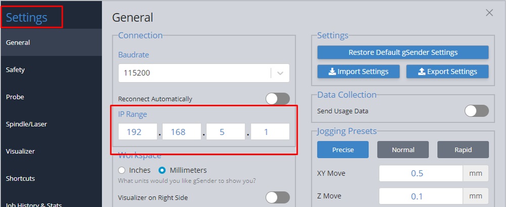
- With the grblHAL firmware selected, choose the ‘Network Devices’ option and you should see it connect successfully 🙂
- If you have a problem connecting with Ethernet, go back over the setup steps. You can also reconnect over USB to double-check your SLB/SLB-EXT Ethernet settings.
Ethernet on Mac
To set up an Ethernet connection to the SLB/SLB-EXT from a Mac, you’ll follow a lot of the same steps as for Ethernet on Windows but after doing Step 2:
- On your Mac, click the Apple menu ➜ System Settings ➜ then click ‘🌐 Network’ in the sidebar (you may need to scroll down).
- Click Ethernet service ➜ ‘Details…’. Note: if your Mac doesn’t have a built-in Ethernet port and you’re using an adapter, look for a service that contains the name of the adapter manufacturer or the type of adapter. For example, the service might be named [manufacturer name] USB-C LAN, or just contain the model number of the adapter.
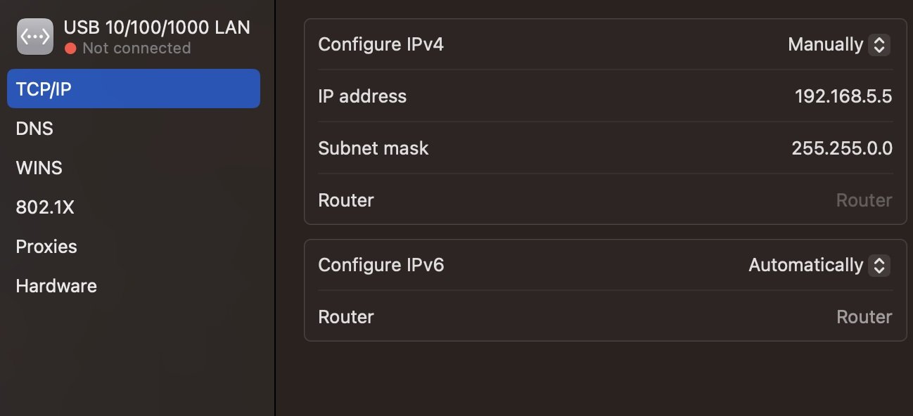
- Click TCP/IP in the sidebar ➜ then for ‘Configure IPv4’ choose ‘Manually’ so you can enter the specific IP address and subnet mask. You want the subnet mask to be the same value from the EEPROM ‘Netmask’. The IP address should have a different last digit on the same mask – so if the board is device 1 (192.168.5.1), you could call your PC device 5 (192.168.5.5). Click “OK” to save and close the options.
- Resume following the Windows instructions at Step 6 to finish the process.
Motors
There is a major difference between the SLB and SLB-EXT in terms of the motors they support.
-
SLB-EXT supports both closed and open loop motors, with external drivers.
-
SLB only supports open loop motors, specifically NEMA 23 or similar.
See the tabs below for more information specific to each controller.
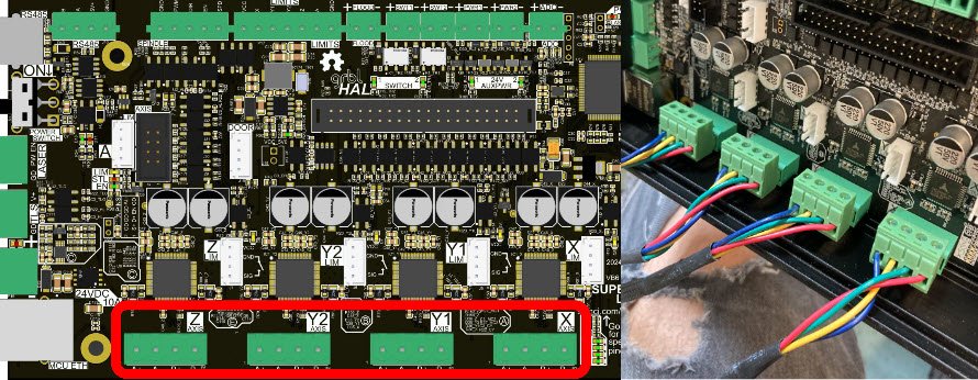
The board comes with 4 onboard stepper motor drivers so you can plug a typical XYYZ CNC router straight in. We recommend putting the left side motor on Y1 and the right side motor on Y2. If you ever need to swap cables around, grabbing the connectors by their sides and wiggling back and forth helps them pop back off easily.
The TMC2660C motor drivers are capable of 2800mA RMS and should allow for faster speeds than the previous LongBoard’s TB6600 drivers due to their higher efficiency which also means the machine runs quieter. Though they can all run independently, the two Y-axes are set up in the firmware to run ‘mirrored’.
SLB Movement & Cutting Speeds
The default movement speed of the SLB has been set up to work out-of-the-box for a LongMill CNC with typical tuning on an average setup. Based on your CNC you may be able to adjust your Maximum Speeds for X, Y, and Z ($110-112), as well as your Acceleration ($120-122) to be higher or lower than the defaults.
To check if your machine is able to handle the default speeds, manually set the jogging ‘Speed’ value in your g-code sender to the maximum default speed and then make long jog movements over the full cutting area, to see if you encounter any snags. If you snag once you’re up to speed then consider decreasing the speed, whereas if you snag at the start then consider decreasing the acceleration of the specific axis.
Alternatively if it seems like your machine handles all movement just fine, then also feel free to experiment by increasing the default values to be higher. Some tips:
-
We recommend increasing acceleration over speed, since the majority of CNC projects consist of small movements (3D or V-carving) where acceleration has a larger impact on carve time
-
Sometimes faster speeds won’t actually make projects run faster since you might be limited by the speed you can realistically cut through the material
- Consequently, higher speeds and accelerations should not dramatically impact machine wear
-
If homing is set up and you are using jigs, please re-check your homing offsets, since motor acceleration can change where your machine homes to.
SLB Microsteps & Movement Tuning
The default configuration for the SLB is 32nd microstepping ($150-153). The more precise microstepping signalling on the SLB’s TMC2660Cs drivers means that they’re able to maintain similar torque no matter the microstep settings. Moreover, coarser microsteps are still interpolated after-the-fact, to make the steps less jarring and reduce resonance. In our testing we found that 32nd worked just as well as 8th, while providing more benefit of reduced motor noise and improved accuracy.
Once you’ve got your steppers plugged in and decided on your microstepping, you should test that your machine moves by the distance you instruct. The easiest way to do it is to use gSender’s built-in Movement Tuning tool.
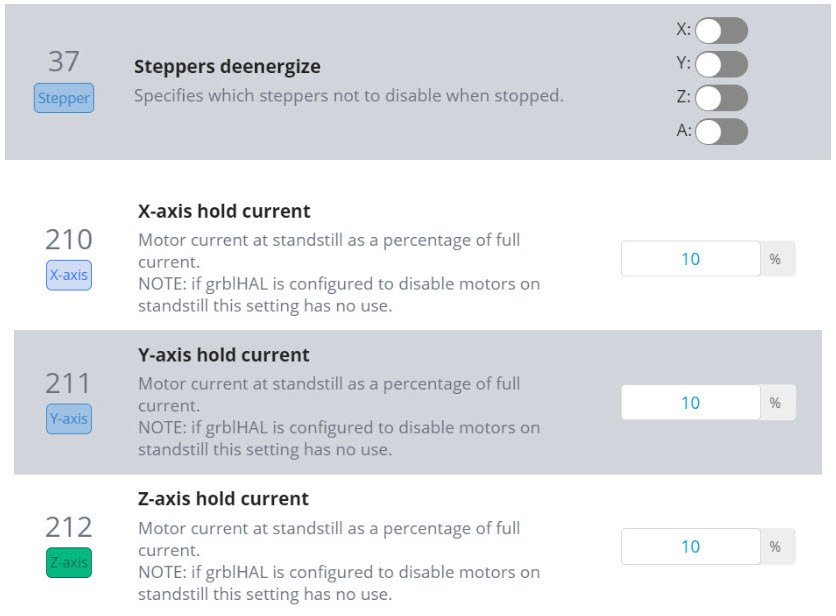
SLB Motor Holding
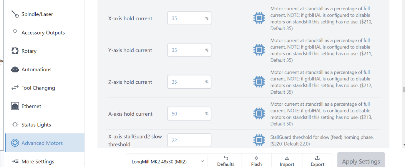
Instead of the old solution of setting $1=255 which forces all motors to hold at full current, two settings allow you to select individual motors that you want to hold, and what holding strength you want to use.
- ‘Steppers deenergize’ ($37), simply toggle the axis you want to hold
- ‘Hold current’ ($210-212) to decide what the holding strength will be (as a % of the motor’s full current, we recommend at least 15% for lead-screw drives)
Useful in cases of:
- Heavy spindle that can lower the Z-axis over time
- Vertically set up CNC
- Stop your motors from losing position in cases where you do manual tool changing
❗Note that these settings won’t work for an A-axis since that would typically be done using the DIP switches on the external motor driver.
‼️Additionally, since the Y1 and Y2 outputs share the same enable pin, they cannot be held independently even if they’re assigned to different axes.
Unlike the regular SLB controller which has its own integrated motor drivers, the SLB-EXT controller is designed to control external motor drivers. In the case of the AltMill, these external motor drivers exist on the motors themselves.
There are two connections that need to be made between the motor and the SLB-EXT controller:
- The 48V DC power that supplies the motor’s drivers. This connection has two cables, with the red being positive and black being negative.
-
The signal connection made between the board and each motor driver. These signal connections utilize differential signals with twisted pair cables to ensure maximum signal reliability.
There are four key connections (using two cables each) which do the following:
-
STEP/PULSE (S+ / S-) is used to instruct the motor driver how many small steps or increments to spin
-
DIRECTION (Dir+ / Dir-) is used to instruct the motor driver which direction to spin
-
ENABLE (En+(5V) / En-) is used to either enable or disable the motor. When the emergency stop button is pressed, all motor drivers are disabled as a redundant safety mechanism in addition to cutting power to each driver. In normal operation, all motors are always enabled to ensure the machine’s position cannot change due to outside forces such as gravity, cutting forces, or being bumped into.
-
ALARM (Al+(GD) / Al-) is used by the motor driver to let the controller know that an error has occurred and the machine’s motor has lost its position. When this happens, the controller will flash an ‘Alarm 10’ and perform an emergency stop to prevent any possible damage. If the machine somehow ran into an obstacle (or itself), the motor(s) involved will shut itself off and send this alarm signal. If this happens, please see our troubleshooting guide
-
SLB-EXT Movement & Cutting Speeds
The SLB-EXT is loaded with default speed and acceleration settings used for the AltMill. Based on your CNC you may be able to adjust your Maximum Speeds for X, Y, and Z ($110-112), as well as your Acceleration ($120-122) to be higher or lower than the defaults.
To check if your machine is able to handle the default speeds, manually set the jogging ‘Speed’ value in your g-code sender to the maximum default speed and then make long jog movements over the full cutting area, to see if you encounter any snags. If you snag once you’re up to speed then consider decreasing the speed, whereas if you snag at the start then consider decreasing the acceleration of the specific axis.
Alternatively if it seems like your machine handles all movement just fine, then also feel free to experiment by increasing the default values to be higher. Some tips:
-
We recommend increasing acceleration over speed, since the majority of CNC projects consist of small movements (3D or V-carving) where acceleration has a larger impact on carve time
-
Sometimes faster speeds won’t actually make projects run faster since you might be limited by the speed you can realistically cut through the material
- Consequently, higher speeds and accelerations should not dramatically impact machine wear
SLB-EXT Microsteps & Movement Tuning
The default steps/mm for the motors is 320 steps/mm for the X and Y, and 200 steps/mm for the Z ($100-102). If you have a third-party CNC, feel free to change as needed for your setup. If you are unsure about these settings, you can calculate the steps/mm by following this short guide.
Next, make sure you have set the DIP switches on your motors to match the steps/mm you have selected.
Finally, any minor differences between expected and actual distance travelled can be compensated using gSender’s built-in Movement Tuning tool.
SLB-EXT Motor Holding
Closed loop motors require constant current to the motors, in order to provide feedback to the motor driver if position is lost. Leave step idle delay as $1=255, otherwise your CNC will not move.
If you have open loop motors hooked up to the SLB-EXT, set step idle delay $1=254, since open loop motors do not need constant current. Then you have the option to adjust the current going to individual motors:
-
‘Steppers deenergize’ ($37), simply toggle the axis you want to hold
-
‘Hold current’ ($210-212) to decide what the holding strength will be (as a % of the motor’s full current)
Useful in cases of:
-
Heavy spindle that can lower the Z-axis over time
-
Vertically set up CNC
-
Stop your motors from losing position in cases where you do manual tool changing
❗Note that these settings won’t work for an A-axis since that would typically be done using the DIP switches on the external motor driver.
Touch Plate/Probe
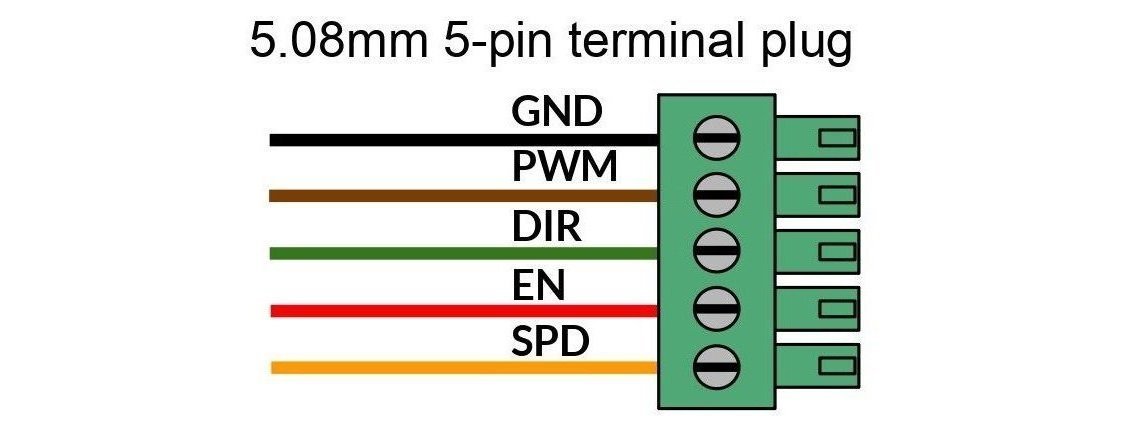
Connect your touch plate or probe here. Any Sienci touch plate and many 3rd-party continuity-style touch plates should work and can be configured through gSender. For most touch plates, it doesn’t matter which way you plug them in.
If your touch plate has a third pin for power, consider wiring it to the TLS input at the back of the board instead, just to make hookup easier. If you plan to use both the TLS and a 3-pin touch plate, then you can pick up 24V from the E-stop plug or 5V from the Ring LED plug. VCC from the AUX Limit Switch Plus is also typically available.

If you want to check continuity, tapping the touch plate and magnet together should turn on the yellow ‘PRB’ LED near the touch plate connector. For a NC probe this behaviour will be inverted.
If you go to probe and find that there’s a touch being detected when there shouldn’t be, either the probe or the TLS signal needs to be inverted. Try toggling the firmware setting $6 or $668, then check again.
Status Lights
A new and simple way to know your CNC status at a glance or from a distance. The RGB light on the board is visible from most angles and shines through the clear cover but you can also hook up more if you want to light up your machine, enclosure, or surrounding work area.
- ⬜ White: CNC is Idle, flashing white means a job has completed
- 🟩 Green: Jogging or Running a Job
- 🟨 Yellow: Paused or the Door is open
- 🟥 Red: E-stop is pressed or an Alarm occurred
- 🟦 Blue: Homing or Verifying a job (check state)
Note: if you ever see the light change from green to white during a job, this is normal and can happen during G4 dwells or when changing spindle speeds.
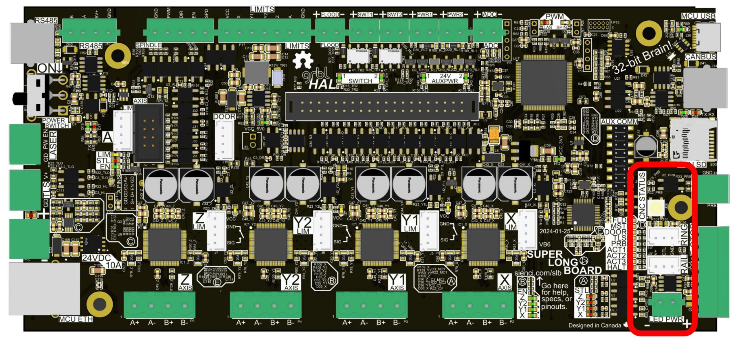
There are also plenty of other status lights on the board for the purpose of troubleshooting, GO HERE to see what they all do.
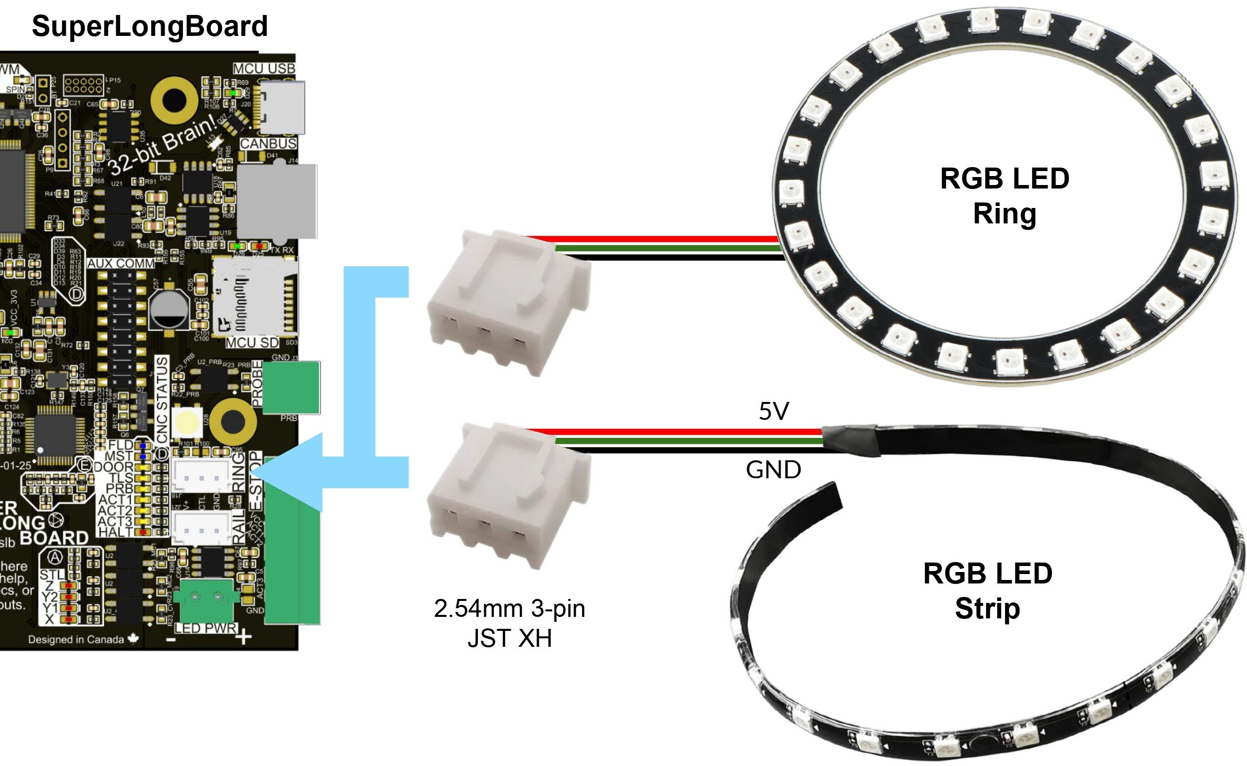
LED Strips
If you want to have RGB LEDs lighting up your CNC, you can connect up to 2 separate strips:
- A shorter strip of up to 40 LEDs, powered by the SLB
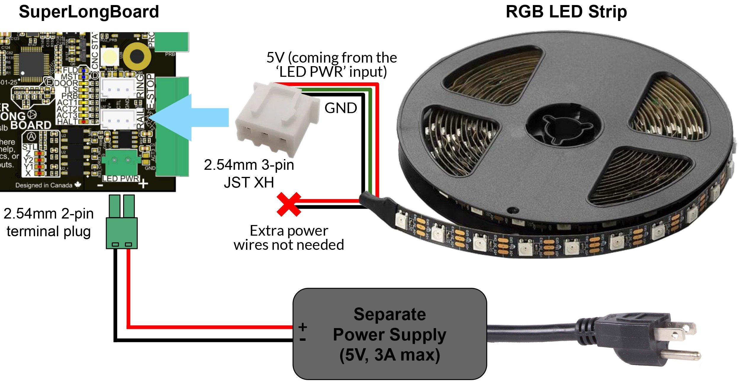
- A longer strip of up to 60 LEDs that needs to be powered by a separate power supply (you’ll need to provide one)
On the SLB/SLB-EXT, the plug for the shorter strip is called “Ring” since you’d typically mount it near your router/spindle to light up the cutting area, while the longer one is called “Rail” since it’s a good length to mount under an X or Y-axis rail for more ambient lighting; but realistically you can use both strips however you want.
If you want to hook these up, make sure you buy the right strips:
- Try to buy just the LED strip, no remote or other circuitry
- It have 3 or 5 wires (not 4) and be marked as “5V” (not 12 or 24 volts)
- If they’re 5V, the LEDs will likely be called “NeoPixels” or “WS2812” in the name or description, check this is true
- Some we’ve tested:
- BTF-LIGHTING (1m/3.3′ strip, 60 LEDs)
- airgoo NEON (two 16″ strips, 42 LEDs)
- Geekstory ring light (78mm ID, 35 LEDs)
- If you don’t want different colours and just want your LEDs to turn on and off, consider using the SLBs AUX Power outputs
- Tip: if you want your Rail LED strip to be longer, try to find one with the LEDs spaced further apart
Typically, LED strips will be wired in the same pattern as the SLB: power, signal, ground (left-to-right) – but with the wrong connector. The plug is a standard ‘JST XH 2.54 3-Pin Female Connector‘ which should be very common to find, where you can either buy the pre-crimped connector and solder it to the LED strip, or cut off the incorrect connector and crimp on a new one.
The bottom “Rail” plug extends from the on-board light to run a much longer LED strip using an external 5V, max 3A power supply (denoted LED PWR). You could mount this strip under your CNCs X or Y-axis rails or use multiple strips to light up your whole enclosure.
Once you’re done wiring up, update these firmware settings to indicate the number of LEDs:
- $664 or $536 for Ring (LED strip 1 length)
- $665 or $537 for Rail (LED strip 2 length)
Then power-cycle the board for the changes to take effect. Look at the new pizazz!
If you’d like to learn more, some members of our community contributed their own setup guides too:
Manual Control
The lights will automatically change colour based on the CNC’s status by default, but if you want to change that you can use the M356 command in the console to make either output stay white (to illuminate your cutting area all the time), turn off, or go back to Auto switching. An example would be using “M356 P1 Q1” to make the ring light stay white. The remaining combinations are shown below:
| Rail | Ring | |
| Auto | M356 P0 Q0 | M356 P1 Q0 |
| White | M356 P0 Q1 | M356 P1 Q1 |
| Off | M356 P0 Q2 | M356 P1 Q2 |
Homing & Limit Switches
Common limit switches are supported on the SLB/SLB-EXT, such as:
- NC (normally closed) and NO (normally open) mechanical switches
- NPN inductive sensors
You can wire one-per-axis or two-per-axis, if you’d prefer to have your CNC set up with hard-stops at the min and max travel. Some switches will already be able to plug straight into the white, 4-pin JST connectors for each axis (like our inductive sensors). Otherwise we’d recommend wiring to the green terminal connector (circled at the top of the picture).
⚠️ For the SLB, do not use the Y2 limit switch plug.

Limit Switch Guidelines
-
Make sure the limit switches are precise and that they stay consistent in different temperatures (check with supplier) – otherwise, the switch might activate 2mm away when you’ve got your shed heater on but 2.2mm away if you open the door
-
Mechanical switches can usually be wired as either NC or NO. If you have the option to choose:
- NC is safer since the wires always carry a signal back to the controller, but if your wiring is loose then it can cause errors at unexpected times
- NO has the opposite problem where if a wire is loose then you’ll only find out once the CNC rams into itself during homing or running a job; some people prefer this since it’s easier to determine the switch/wire is bad in the moment, but it’s less safe and can cause damage
-
Occasionally check your wiring to make sure nothing is loose – all switches share the same ground and VCC signals, plus individual limit signals, so a false trigger could ruin a job
-
Using shielded cable can help dissipate electrical noise in the wires and prevent unexpected triggers
Limit Switch Wiring
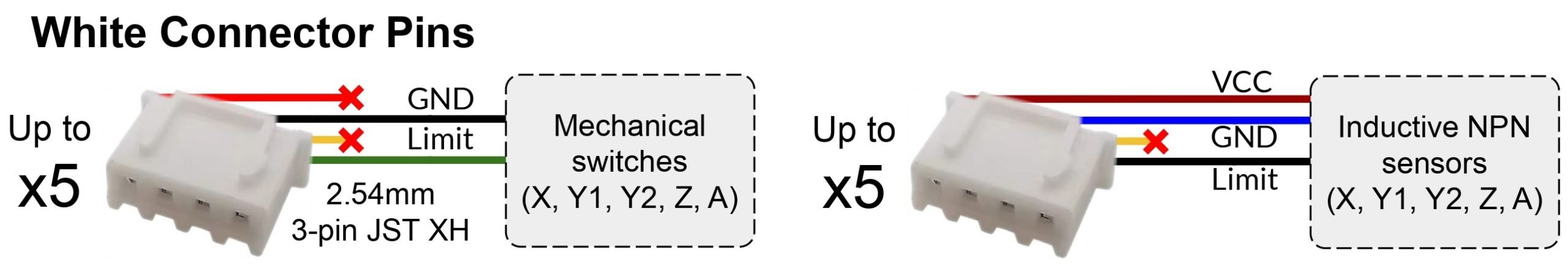
Using the big green connector is the same as using the smaller white JST connectors, they are connected to each other on the board so it doesn’t matter which one you use. The terminal pinouts are VCC, X, Y1, Y2, Z, A, GND going left to right, and the JSTs are VCC, GND, N/A, LIM going top to bottom. The most common custom setup is shown below (NC switches or NPN sensors wired to the green connector).
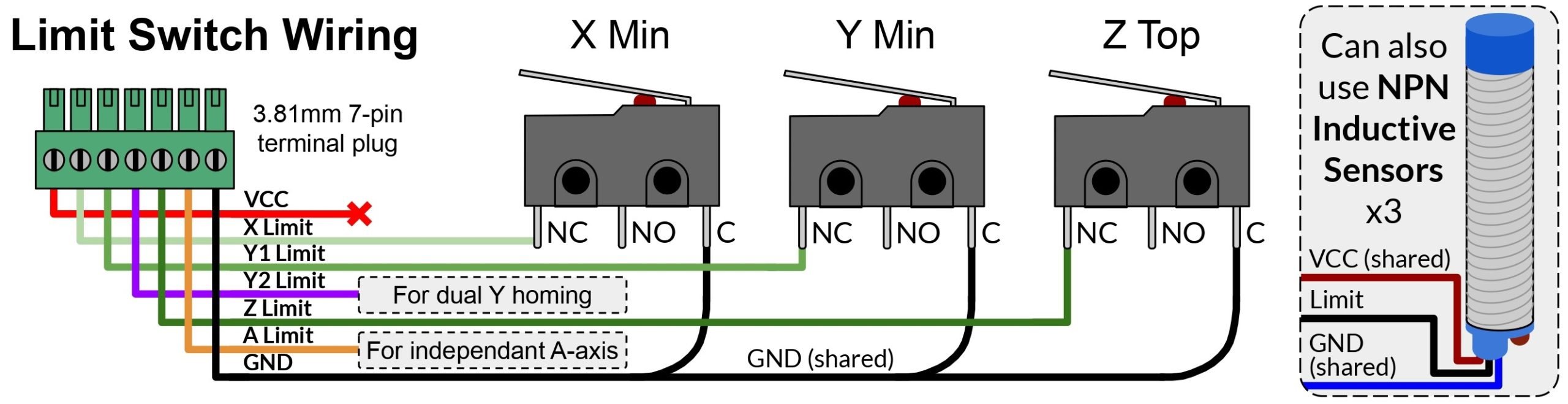
By default, VCC outputs 5V. If you want to wire for a different setup, see below for other wiring variations:
- NC (also already shown above), NC with hard-stops
- NO, NO with hard-stops
- NPN (already shown above), and NPN with hard-stops
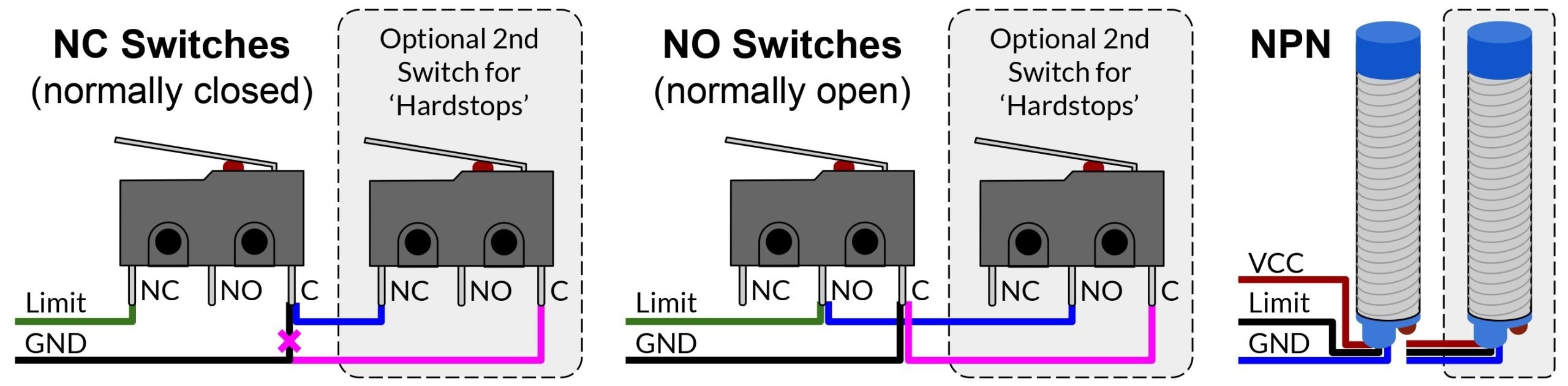
If you’d like to use the white JST connectors instead, the wiring pinouts are below for both mechanical switches and inductive sensors. All VCC outputs can also be changed from 5V to 24V if you’d like (user-made video by SparksTech) by breaking the 0Ω resistor on R9 and creating a solder bridge across R10 (outlined in red in the middle of the first homing picture).
Limits Settings
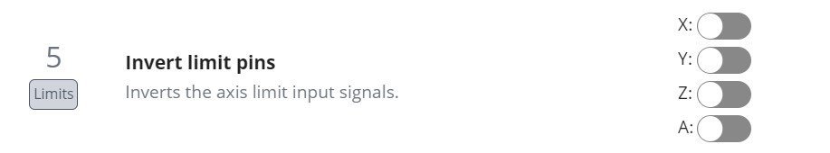
If you’ve set up your own NC sensors, the first thing you’ll want to do is turn ON the toggles for the invert limit pins ($5) setting, like shown below. Don’t do this if you have the inductive sensors from Sienci!
Current
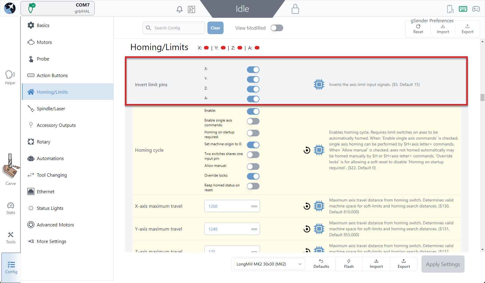
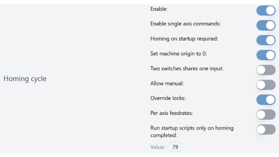
We recommend you enable all the ‘homing cycle'($22) settings shown in the picture, otherwise the table below will explain these settings so you can turn on the ones you need.
Classic gSender
We recommend you enable all the ‘homing cycle’ ($22) settings shown in the picture, otherwise the table below will explain these settings so you can turn on the ones you need.
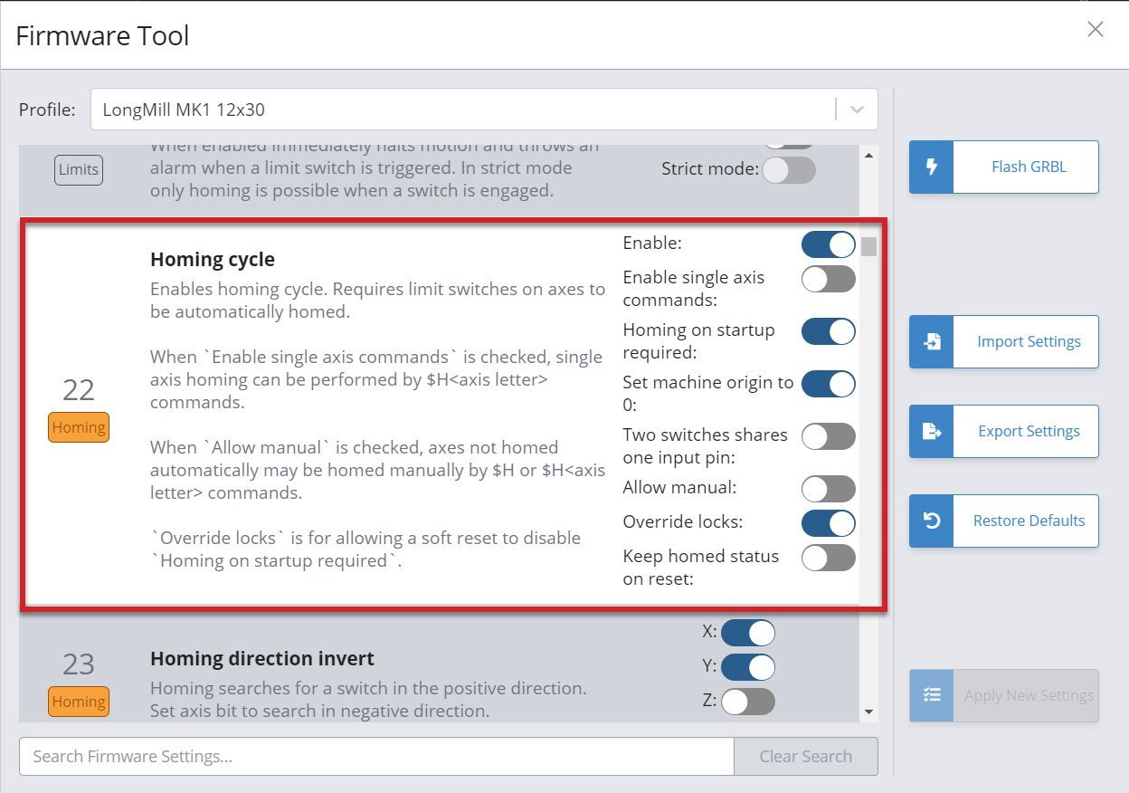
| Setting | Description |
| Enable | Turns on homing |
| Enable single axis commands | Allows special homing commands so you can, for instance, re-home only your Z-axis without having to re-home the whole machine |
| Homing on startup required | Reminds you to home your machine every time you power it on, since CNCs typically lose their position when they lose power |
| Set machine origin to 0 | Typically enabled so that re-homing re-zeros the machines location |
| Two switches share one input pin | Enable if you plan to set up hard limits at the end of each axis |
| Allow manual | If you want to home an axis that isn’t homed when you ‘Home all’ |
| Override locks | In case you’ve turned on ‘Home on startup’ but want to skip it in certain cases |
| Keep homed status on reset | In a case where the machine is reset, it’ll try it’s best to maintain the machine position and not force you to re-home |
Some other new settings that have been introduced include:
-
$21: expanded to introduce a “Strict mode” which you can turn on if you want the machine to be forced to home if a hard limit is triggered
-
$40: added to stop soft limit alarms from appearing when jogging. This can only be turned on if you’ve turned on homing first.
If you need any other refreshers on how to set up limit switches or troubleshoot them, see our MK2 resources here.
❗Note: If you ever change homing settings like seek rate, locate rate, debounce delay, or pull-off distance, this will change the location your machine homes to, so if you’ve set up any work offsets you’ll need to adjust them accordingly.
Dual Y-axis Homing
By default, the SLB-EXT is set up for ‘dual homing’, which allows the machine to automatically square its X and Y axes to one another, through two limit switches on the left and right of the Y-axis. It’s essential that you plug in the matching limit switch and motor cables to their corresponding Y-axis plug. A motor and limit switch mounted on the left side of your machine should both be plugged into ‘Y1’, or ‘Y2’, not mixed between left and right.
At this time, dual homing is not available by default on the SLB. However, it is possible to get the dual homing feature by reflashing the controller with new firmware.
⚠️ Please note that this is a tricky process and any mistakes can cause your controller to be inoperable, proceed at your own risk. Firmware Flashing Instructions
Laser
If you have a laser diode accessory for your CNC, you would connect it onto the Laser port on the SLB/SLB-EXT. Use the top three pins if your laser driver needs an ‘Enable’ signal to operate, otherwise just use the bottom two to get the 5V PWM output that most laser accessories typically need. On the LongBoard this would’ve normally been the 2-pin SpinPWM plug, which you can plug straight into the SLB/SLB-EXT.
⚠️ Warning: Lasers are very dangerous devices that can instantly damage your vision and cause fires. Be informed on how your laser works, and how the controller and g-code sender handles laser commands.Treat your laser with caution and respect and turn off power to the laser driver when you're not using it. If you have the driver turned on, everyone around should always be wearing eye protection and there should also be clear warning or signage to protect others.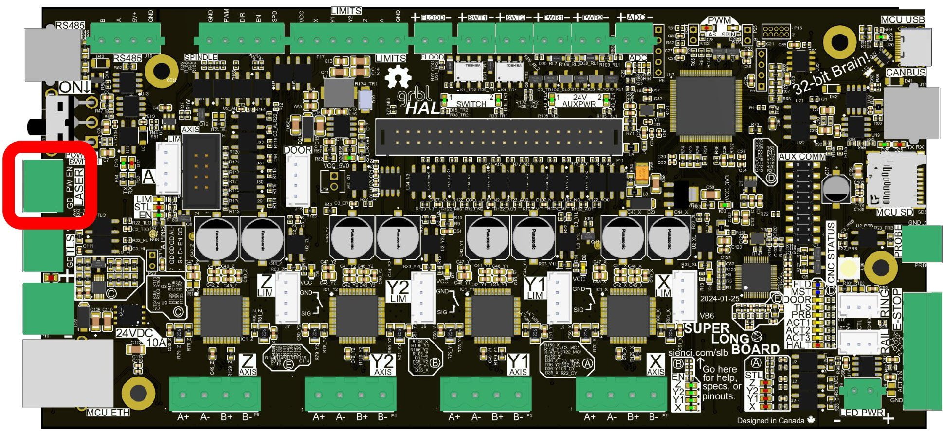
Follow your manufacturer recommendations for where to mount your laser driver and electronics. This will probably be in a more secluded spot away from dust and vibrations, since laser electronics tend to be more sensitive and require more air cooling.
Read more on laser wiring, safety, and use in this article.
Laser Settings
These are the relevant settings that you may need to adjust to use your third-party 5V PWM laser:
- $709 PWM2 Spindle options
- Only applicable in the latest firmware
- Typically 19
- 716 PWM2 spindle signals invert
- Only applicable in the latest firmware
- Typically 0
- $730 Max laser power/PWM2 spindle max speed
- Whatever max laser power your laser calls for, typically 255
- $731 Minimum laser power/PWM2 spindle min speed
- Typically 0
- $733 Laser PWM frequency/PWM2 spindle PWM frequency
- Can go to a theoretical max of 100kHz
- Check your diode manufacturer’s site to see if they specify a frequency range, then try to set it to the higher-end of the range for best results
- $734 Laser PWM off value/PWM2 spindle PWM off value
- Typically 0%
- $735 Laser PWM min value/PWM2 spindle PWM min value
- Typically 0%
- $736 Laser PWM max value/PWM2 spindle PWM max value
- Typically 100%
- $741 and $742 or $770 and $771 Laser X and Y offset
- The distance between the spindle and laser heads
- Applied automatically when switching between spindle and laser
- $743 Invert laser signals
- This setting is unavailable in newer firmware
- Typically Laser enable = off, Laser PWM = off
Laser Settings Configuration Files
20260318 and above Firmware
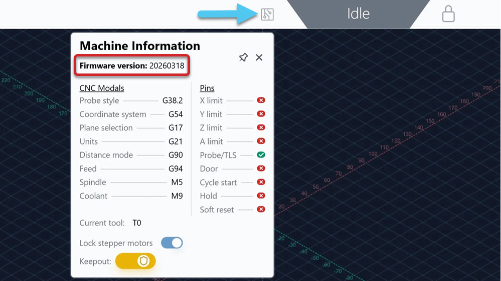
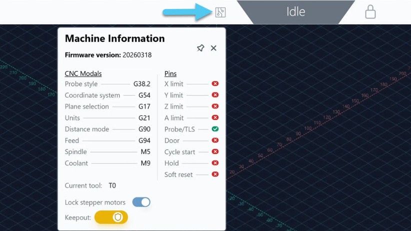
Instead of manually adjusting the settings, you can download and run the g-code file below to have the settings automatically apply. Ensure you have gSender 1.6.0 or above, and check the firmware version of your controller. 20260318 firmware or above is needed!
-
Download the Laser Config File (20260318 and up)
-
Run the file on gSender. Your controller will disconnect.
-
Turn OFF/ON the controller to have the settings take effect. Then reconnect to gSender.
Older Firmware
Instead of manually adjusting the settings, you can download and run the g-code file below to have the settings automatically apply. The file below is for versions older than 20260318, such as 20230917.
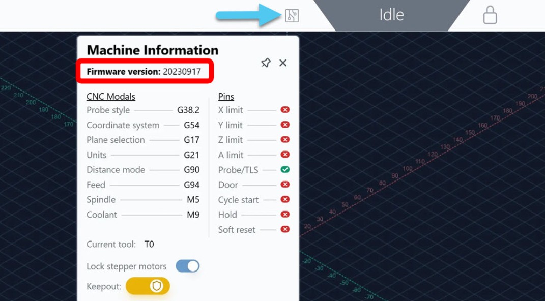
-
Download the Laser Config File (20230917 and below)
-
Run the file on gSender. Your controller will disconnect.
-
Turn OFF/ON the controller to have the settings take effect. Then reconnect to gSender.
Laser Control
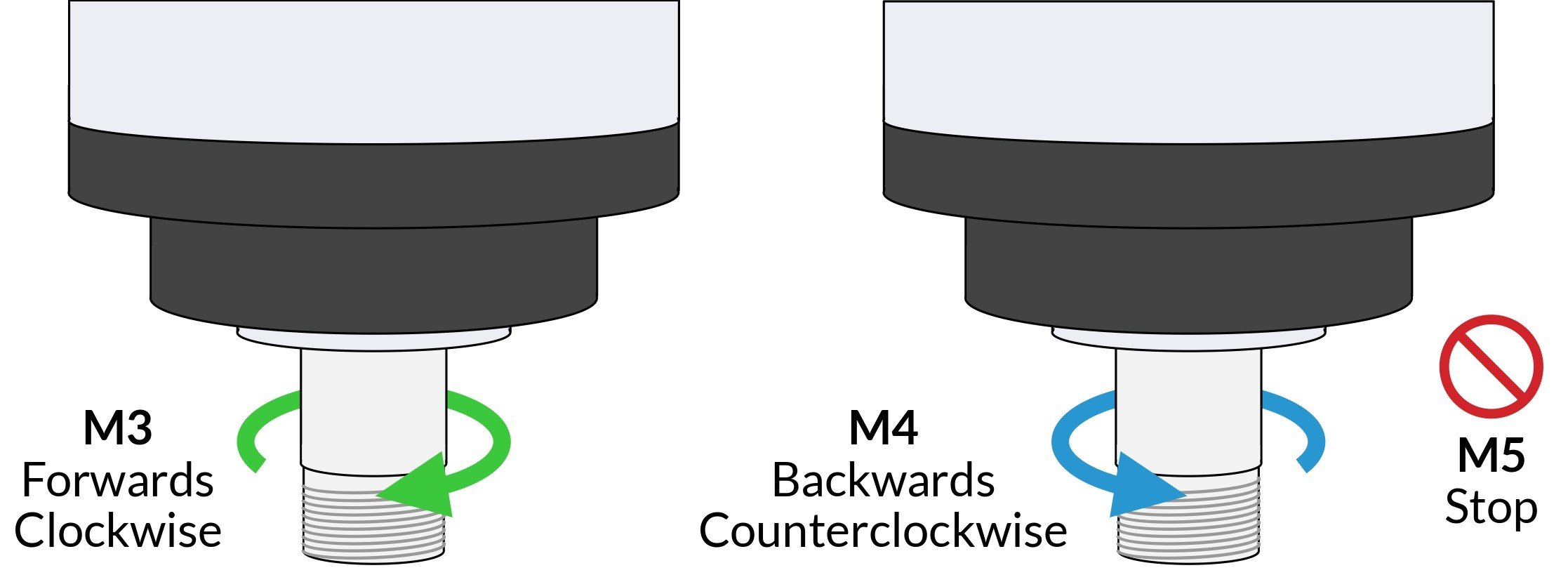
The way the laser is set up on the SLB/SLB-EXT is quite unique. Essentially when your g-code files have spindle commands in them (M3, M4, S##, M5), you have the ability to tell the controller what output you want it to control with those commands, like:
- A basic spindle
- A laser
- More advanced VFDs using the RS485 output
To enable and turn on your laser:
-
Go to Config and under Spindle/Laser, toggle ON Spindle/Laser controls
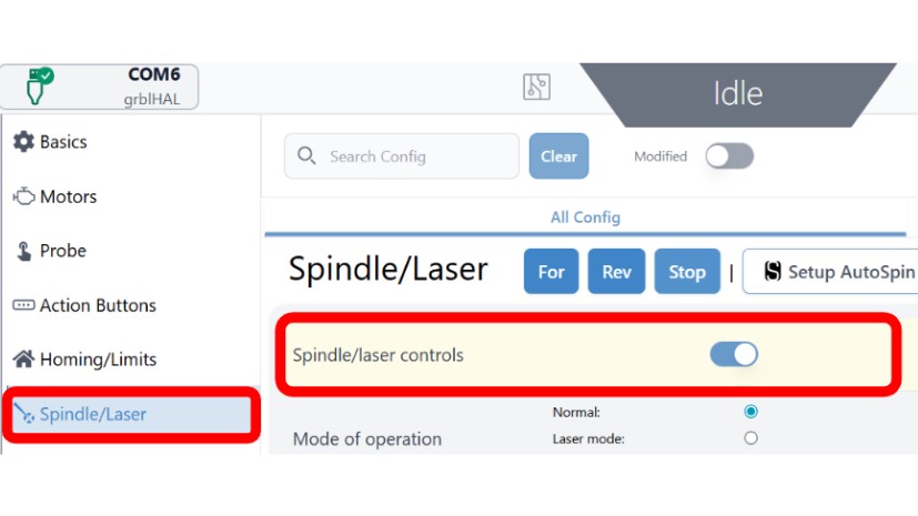
-
Press Apply Settings then turn OFF/ON your controller. Reconnect back to gSender.
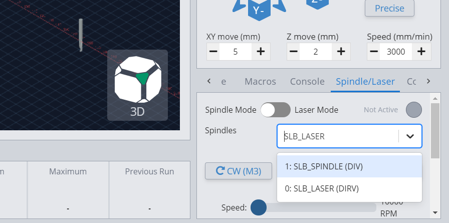
-
On main screen, open the Spindle/Laser tab at the bottom right corner. In the dropdown, select SLB_Laser or PWM2, whichever one you see. You can only control one output at a time.
Current

 output selected in dropdown")
Classic gSender
Here’s a video that explains more about the setup and configuration process (note that the polarity of the wires shown in the video is reversed):
Then use the toggle to switch to Laser Mode, make sure you are wearing eye protection!
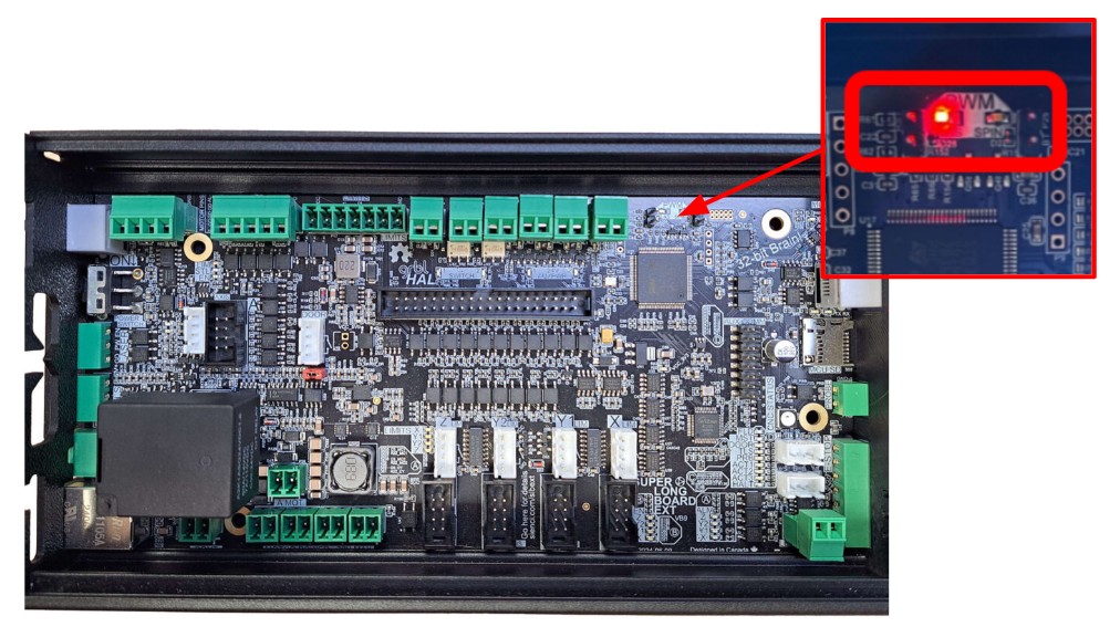
Press Laser On to turn on your laser. Besides the obvious beam from your laser diode, you should also see the red PWM light on your controller turn on.
With your laser now set up, you should be able to use the controls on gSender to activate and power your laser on and off, as well as vary the Laser Test power.
If you are not seeing the laser turn on, we recommend to disconnect the laser from the controller, then use a multimeter to check that your PWM output can go between around 1V and 4.5V. If not, double check your wiring and settings again.Other g-code Senders
For other g-code senders, you’ll need to use the selection commands, since there is no dropdown selection for toggling between spindle/laser outputs.
-
First enter the “$spindles” command in the Console which will list all the options and which one is currently selected.
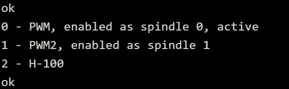
-
Then, enter this command to select the output you want to activate.
- M104Q0 will switch to the 0 option (e.g. PWM)
- M104Q1 will switch to the 1 option (e.g. PWM2)
- M104Q2 will switch to the 2 option (e.g. H-100)
Laser as Default Spindle
The laser isn’t set as the default spindle for safety reasons, but further down is information on how to switch it to be the default, if you use it often. In any case, the laser must be set as the Default Spindle, Spindle 2 OR Spindle 3, in order to activate it later.
-
On gSender, go to Spindle/Laser settings in Config.
-
Select the laser option in either the Default Spindle, Spindle 2 or Spindle 3.
❗Older firmware will call the laser option SLB_LASER
‼️New firmware will call the laser option PWM2
 output")
Spindle 2 set as PWM2 (laser) output -
Save these changes, then turn OFF/ON the controller. Reconnect to gSender.
Action Buttons
With the SLB/SLB-EXT you can set up three customizable buttons to control your CNC however you prefer. These actions can be something simple like starting or pausing a cutting job, toggling a signal to an IOT relay, or even custom g-code for probing, or moving the cutting head backwards once you’ve finished a job. These buttons are available on the controller’s E-stop, but you can also digitally short the pins to ground through the E-stop connector if you want to do custom wiring.
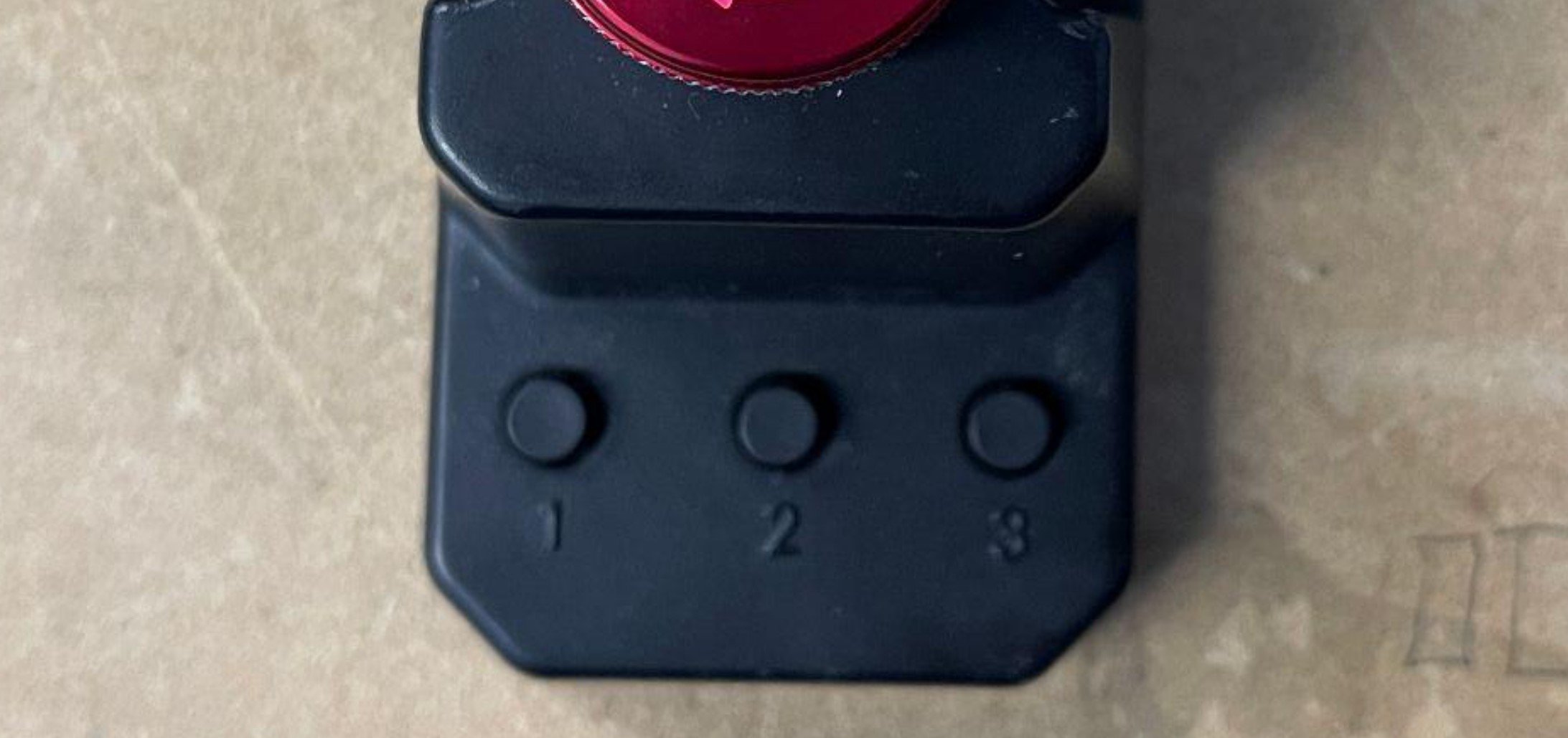
By default, the Action buttons have been set up so that 1 is Resume, 2 is Pause, and 3 is Stop. There is the full list of pre-made actions like this that you can choose from such as:
- Resume running g-code (uses cycle start ‘~’)
- Pause movement (uses hold ‘!’)
- Parking Pause
- Stop movement (uses halt ‘0x18’)
- Toggle on/off the Spindle while paused (similar to M3/M5, uses ‘0x9E’)
- Toggle on/off Flood (similar to M8/M9, uses ‘0xA0’)
- Toggle on/off Mist (similar to M7/M9, uses ‘0xA1’)
…or you can run your own custom ‘macro’ g-code. Here are some examples of macros some users have set up:
- Home all axes: $h
- Zero XYZ to current location: G10 L20 P1 X0 Y0 Z0
- Tweak Z-zero down 0.1mm: G10 L20 P1 Z0.1
- Park the CNC away from the job: G91 G21 G0 X400 Y400
-
Return to the cutting area (XY0 point): G90 G21 G0 X0 Y0
⚠️ We can’t guarantee the g-code above will work correctly for your setup or possibly break things so use at your own risk.
The buttons are customized using the Config/Firmware tab on gSender. Look for settings $450-452 or $590-592 to select one of the actions from the pre-made list. Otherwise, type in your own g-code string to execute in settings $490-492.
Example Button Setup
Some have “go to XY0” and “move to back corner” macros programmed into the action buttons, as it’s way easier to hit the button at the end of a carve to move out of the way, then jump back to 0 when you’re ready to load the next piece. In this example, button 1 turns on the Shop Vac control using an IOT Relay, then button 2 brings the CNC to the previous zero point and button 3 moves it out of the way.
$450/$590 Button 1 Action: Flood Toggle
$451/$591 Button 2 Action: Macro
$452/$592 Button 3 Action: Macro
$454/$491 Button 2 Macro (Go to Z-up, X0 Y0): G53 G21 G0 Z-1|G0 X0 Y0
$455/$492 Button 3 Macro (Go to Z-up, XY to the back right. Need to validate your travel limits): G53 G21 G0 Z-1|G53 G21 G0 X805.000 Y850.000
If you need help making your own custom macro, you can look at gSender’s ‘Console’ tab when you press different buttons to see what’s happening behind the scenes and get some inspiration. Each macro can hold up to 127 characters, can run multiple lines using ‘|’ for a line break, and runs any vanilla g-code but no math operations.
There are also a handful of more advanced pre-made actions such as:
- Toggle on/off Probe Connected
- Currently not used on SLB/SLB-EXT. Implemented as a toggleable check for probe contact while in motion or performing other tasks, read more here: https://github.com/Expatria-Technologies/grblhal_probe_plugin
- Toggle on/off Optional Stops
- When enabled, M1 commands act like pauses just like M0 commands
- This helps test a file. If you insert M1 commands at certain checkpoints in your g-code, you can pause at those checkpoints while this is enabled, then disable ‘optional stops’ to then run the job as normal
- Toggle on/off ‘Single Block Mode’
- This is a very safe way to test a file (usually you’d check just the start of the file) since this mode only runs one line of g-code at a time for each Cycle Start button press
- Find more information about grbl commands here: https://github.com/gnea/grbl/blob/master/doc/markdown/commands.md
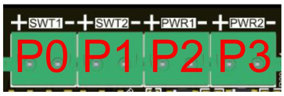
Accessory Outputs
This is where you can get fancy; level up your CNC by controlling more accessories to create your own custom setup. Control IOT relays, power relays or solenoids, switch on even more LED strips, and more! This takes the form of 5 plugs: Flood, Switch 1 and 2, and Auxiliary Power 1 and 2 (going left-to-right, ‘+’ then ‘-‘). These are all 2-pin plugs that either output a voltage or can switch power through them like a low-power relay.
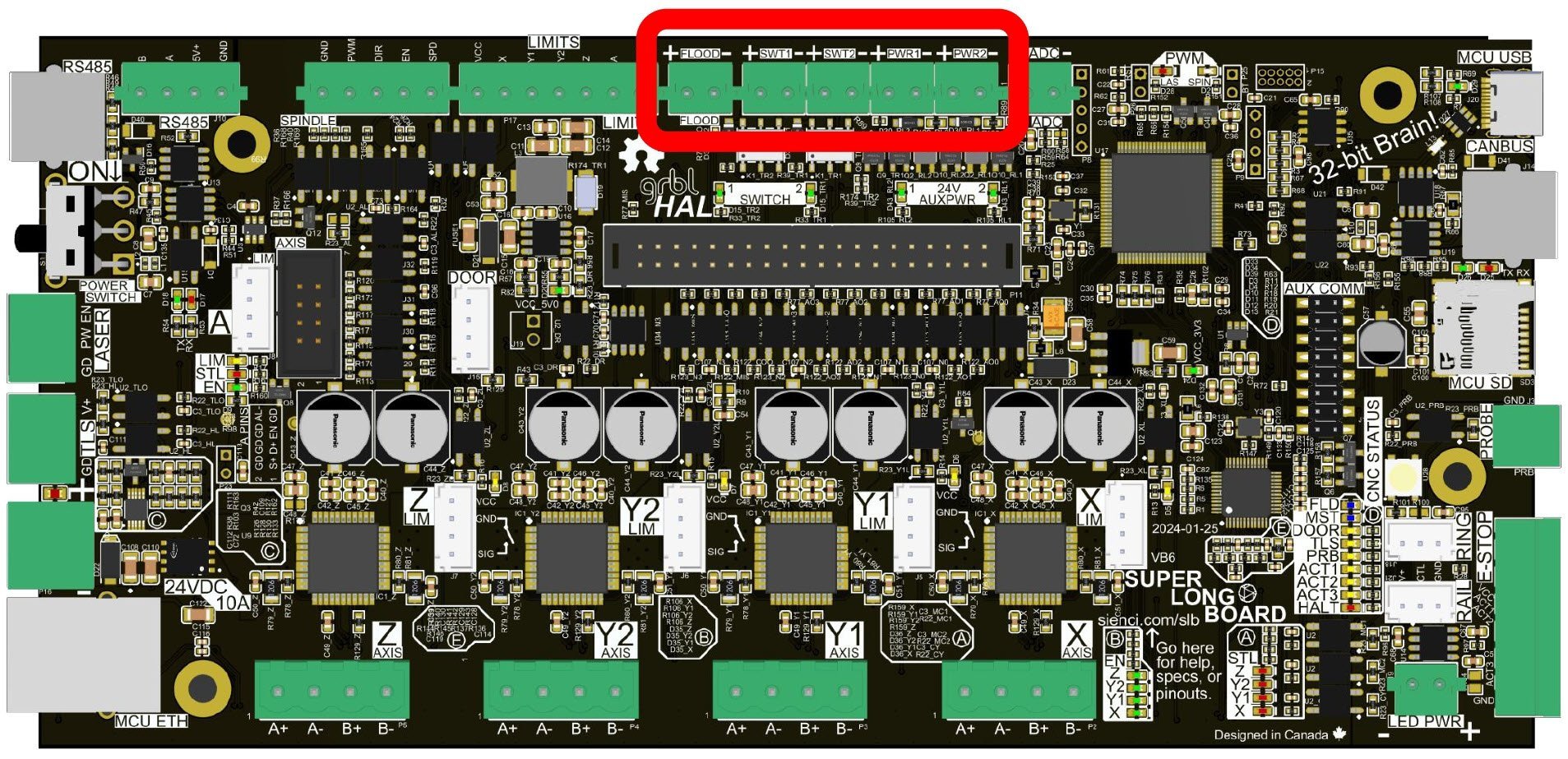
Flood
If you’ve used a ‘Coolant’ output previously, this 5V output still serves the same function. Simply turn the digital signal on or off using M8 and M9 commands either manually, in g-code using your post processor, or using your g-code sender’s start/end g-code code blocks.
This output is commonly used to automatically control a vacuum or router to turn on/off at the start/end of a job using an IOT Relay. It also can be used for any other purpose with any component that accepts a 5V 40mA digital signal.
Read more about setting up an IOT Relay here.
Switch & Aux Power
These outputs offer built-in options for more unique control than just a simple digital signal:
- Switch 1 and Switch 2 outputs are like electrical switches that you can use to ‘switch on’ any external 1-24V circuits up to 1A. This means you’ll need to provide an additional power supply separately to the circuit. Think of these like a mini version of a relay, known as a MOSFET.
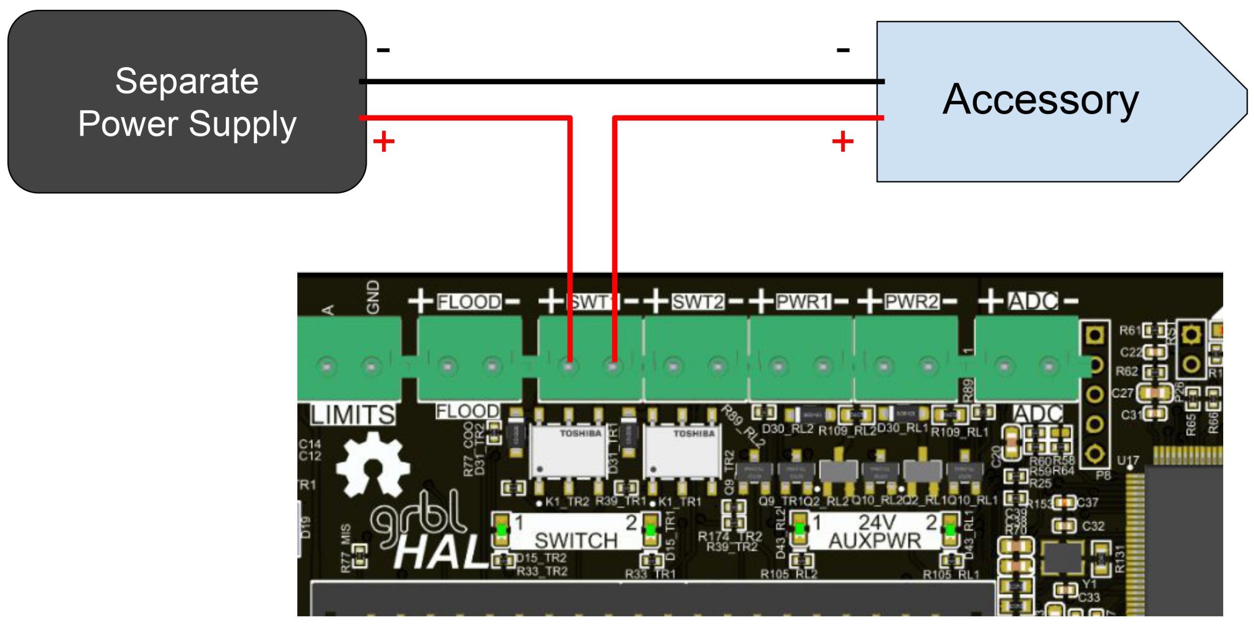
- Auxiliary Power outputs 1 and 2 can be used to provide 24V to any powered accessory like a relay, SSR, solenoid for a mister or ATC, or LED strip; up to 250mA per plug. This can be more convenient for powering less power-hungry components since the power comes straight from the SLB/SLB-EXT. It also makes more sense if you plan to use an SSR to switch an air pump, dust collector motor, or spindle water cooling pump on and off.
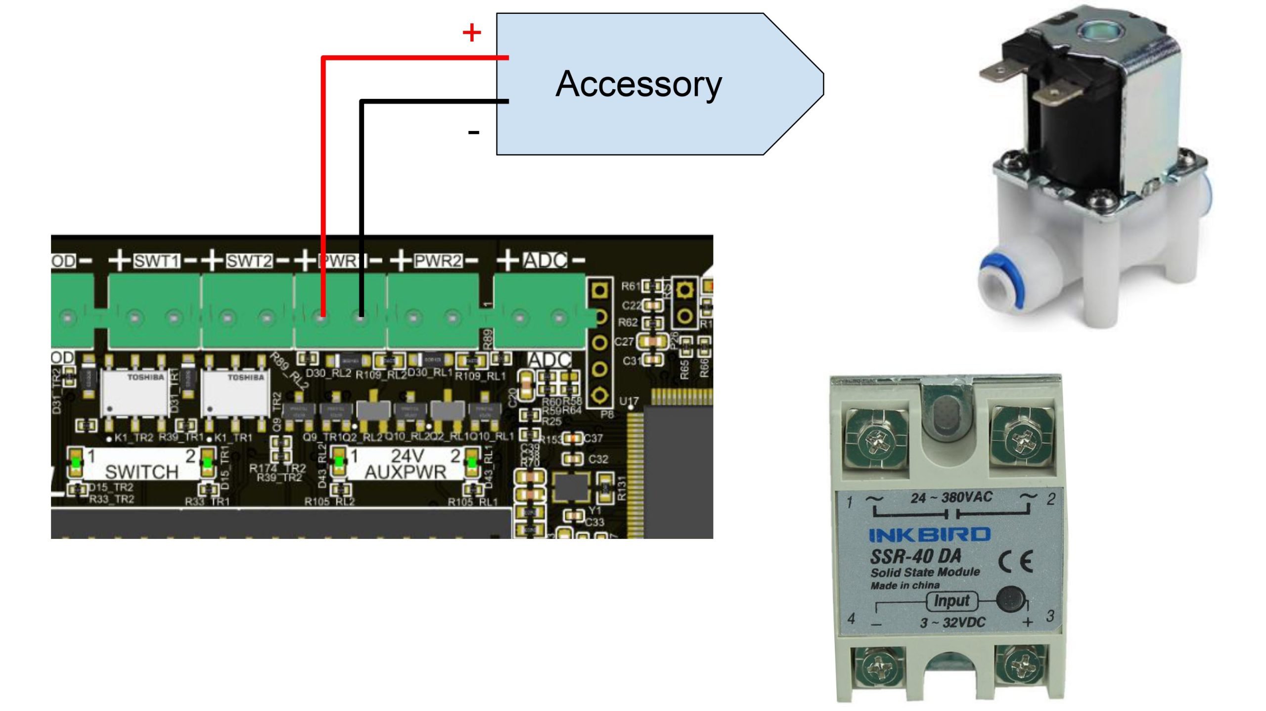
Note: Be mindful that these ‘turn on’ by enabling current flow to the ‘ground’. This means you can’t typically use them to drive logic, only to drive current components, and also that the 24V is always ‘live’.
You can also customize what M commands will turn each of these outputs on and off in the controller’s firmware settings. The $456-459 or $750-753 settings give you 4 options to choose from (SWT1, SWT2, PWR1, PWR2):
- Spindle/Laser Enable (M3/M4): turns the output on with M3 or M4, and off with M5
- Mist Enable (M7): turns on/off with M7/M9
- Flood Enable (M8): turns on/off with M8/M9
- M62-M65 Only: always available as a backup to control each port with a unique M command:
- Turn on/off with M62/63 (but wait in line before running)
- Turn on/off immediately with M64/65
- Use a ‘P’ command to choose the port to control (pictured below). For example “M64 P1” would turn on the SWT2 port immediately.
- Read more here: https://linuxcnc.org/docs/html/gcode/m-code.html#mcode:m62-m65
Similar to the ‘Flood’ output, you’ll now also be able to control ‘Switch’ and ‘AuxPwr’ outputs either manually, in g-code using your post processor, or using your g-code sender’s start/end g-code code blocks.
Spindle/RS485
As mentioned in the Laser section above, we designed the SLB/SLB-EXT for a wide range of CNCers, like those with both a VFD and laser diode accessory on their CNC. Our solution was a PWM laser output, PWM spindle output, and an output for Modbus over RS485 – allowing for control of up to 3 accessories without rewiring and with settings stored independently for each.
Both flavours of spindle signals are there to give you the 2 most popular options for talking to VFDs. The PWM simple signals tend to have easier setup with less fuss, meanwhile RS485 requires more work but provides better, two-way communication during cutting. For either of these to work, ensure you have the controller and VFD wired up correctly and with the right settings.
Note: currently the controller doesn’t support SaS (‘Spindle-at-Speed’, a signal that some VFDs can send back to the board so that the board can wait for the spindle to speed up before starting the cutting process).
If you opted for an out-of-the box experience by picking up a Sienci Labs Spindle Kit, then you DO NOT need to reference any of the following docs, since all the work is done for you.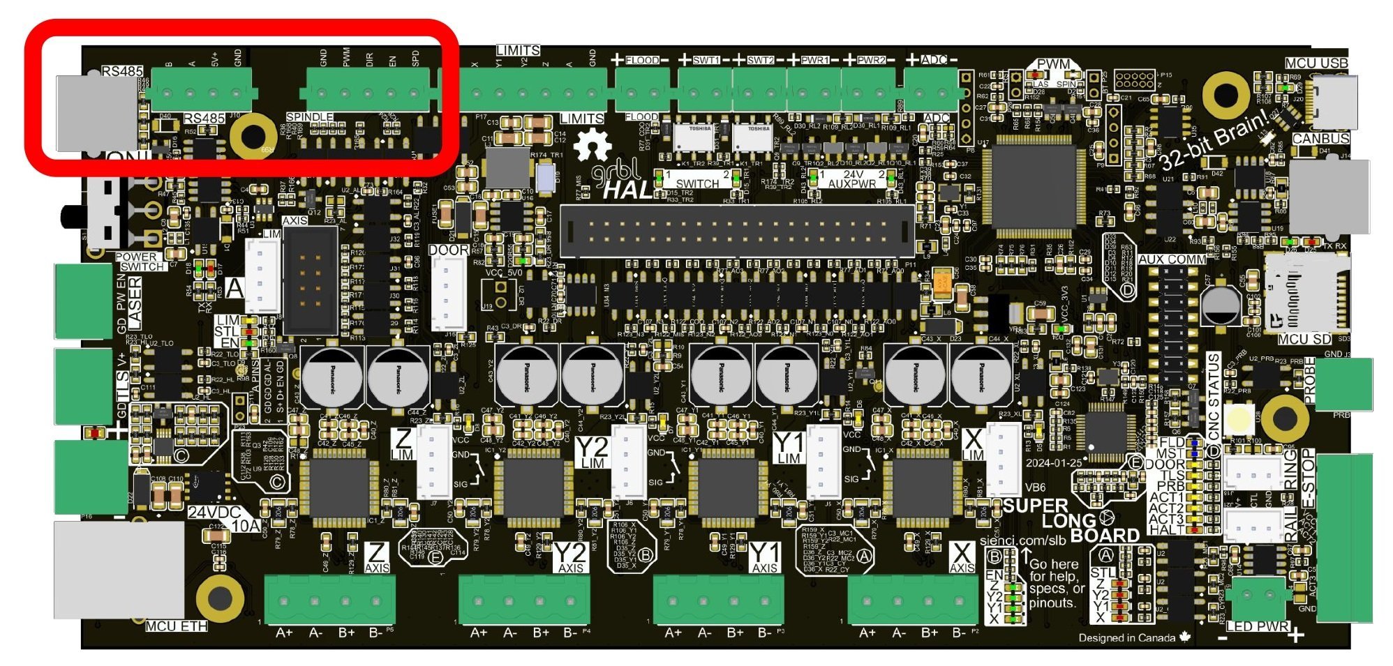
VFD Safety and AC Wiring
Before diving into spindle hookup, it’s important to mention a couple things for your safety:
- Though we’ve tried our best to provide guidance on spindle hookup, there are many spindle kits out there with mixed up VFDs – we’ve even seen cases of VFDs being mislabelled as the wrong model. Because of this, none of the below spindle instructions can be given with any guarantee or warranty, you must accept the risk as we will not be liable for your safety, injury, or damages as a result of these instructions.
- If you buy from a trusted vendor, then specs and hookup instructions should be more straightforward, but if you buy from a cheaper vendor then expect to have to go through more trial-and-error.
- Related to that, cheaper kits also typically require you to do mains wiring manually. PLEASE BE CAREFUL AROUND AC WIRING, and please use best practices throughout the process.
- Lastly, once you’ve hooked up your spindle to the controller, please be aware that the spindle could turn on or off without you expecting it. Examples of this could be when resetting the board, leaning on your keyboard, mouse, or Action Buttons, running unknown g-code, running a macro, and more. Please use caution when operating the spindle.
If you have any inquiries or questions, please direct them to the manufacturer of your spindle or VFD or check the manual.
Initial Checks
-
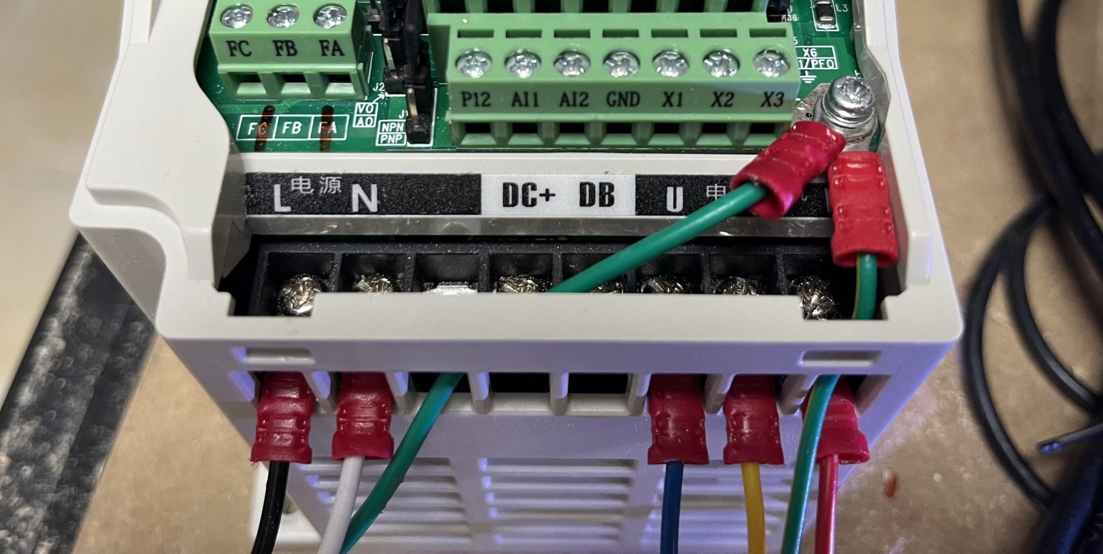
Ensure mains power is connected to your spindle VFD with appropriate wire gauge (recommended #14 to #12, rating should be printed on cable). The VFD should have 3 input terminals (R, S, T or L,N) and a Ground/Earth hookup (indicated by a ground symbol, metal plate, and sometimes red wax on the screw) where for 110V Hot (black) is connected to R or L, Neutral (white) to S or N, and Ground (green or yellow+green) to Ground. If you have 220v, the second Hot goes to T.
-
The wire from the VFD to the spindle should be well-shielded to help reduce issues with EMI. Typically the VFD will have 3 output terminals (U, V, W) that connect to pins 1, 2, and 3 respectively on the spindle. The 4th pin should be grounded to the spindle body, through to the VFD ground, or you can run your own separate wire if you’d like.
-
If your spindle came pre-wired, you can likely skip to this step. You’ll want to make sure the spindle and VFD work exactly as expected when controlled manually using the panel on the VFD. This includes: start, stop, forward, reverse, and controlling speed. ‘Forwards’ should make the spindle turn clockwise when looking at it from above, if this isn’t the case then swap the U and V wires on the VFD.
VFD Settings
VFD Factory Reset
You may want to reset your VFD to factory settings, before you make further changes to settings.
- Find the “Parameter Reset” setting, in common VFDs it’ll be ‘013‘
- Set the value to ‘8‘, telling the VFD to reset all settings
- Power off the VFD by waiting for the display to turn off
- Power it back on, and compare a few settings against the manual to check that it reset properly
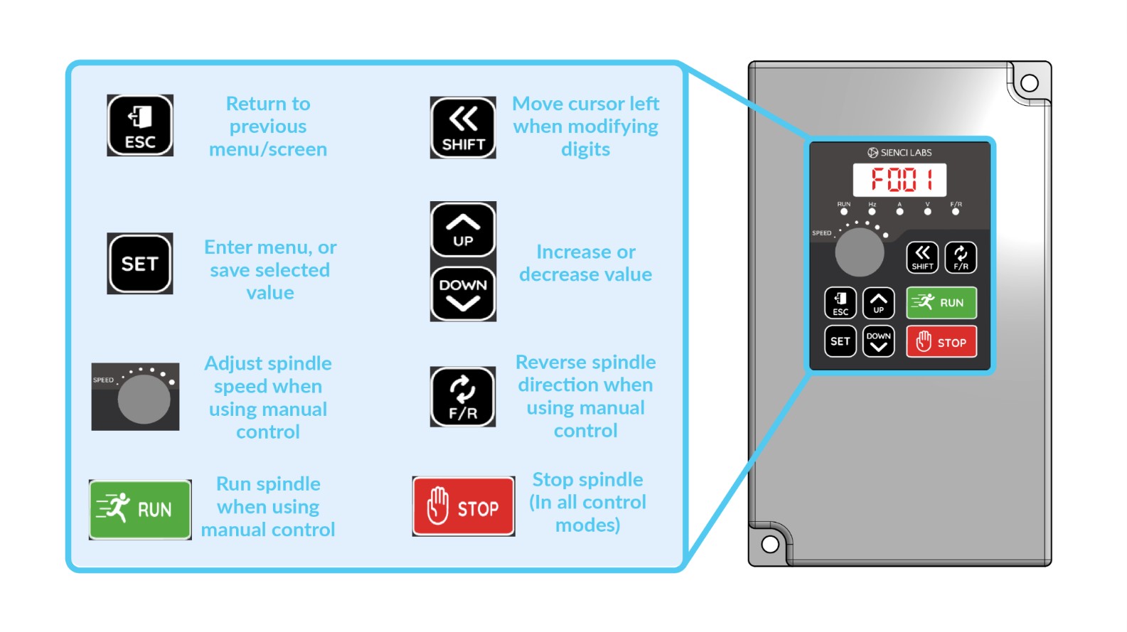
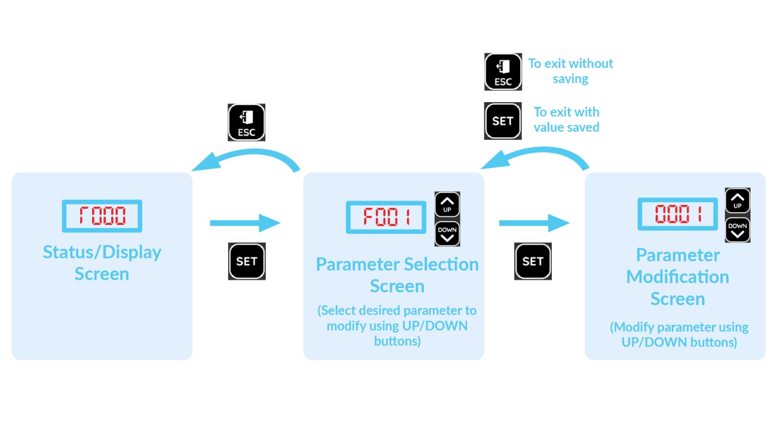
Next, if your VFD wasn’t pre-programmed from the manufacturer for your specific setup, then you’ll likely need to adjust some settings using your VFDs built-in keypad. Most VFDs share 5 similar buttons where you’ll press:
- PRGM/SET/PROG to enter into the settings menu
- Use the UP and DOWN arrows to cycle digits from 0-9 and use SHIFT/← to move left to edit higher digits
- Use this to go to the setting you’d like to check
- Example: if you start with “000” and you want to get to setting “023” then you’ll start with the right digit highlighted (000), press UP 3 times (003), then SHIFT to get to the next row (003), then press up twice more (023).
- Press SET/DATA to open up the setting
- Use the same UP and DOWN and SHIFT/← buttons if you want to change the setting value
- Press SET/DATA if you’d like to save the new value, or press PRGM/ESC/PROG to leave without saving
- You can go back to the setting to check that it’s been set correctly
Example Huanyang Setup
Huanyang v1 VFD set up as “Spindle 1” on the controller (the secondary option) over RS485:
- On the VFD interface:
- PD001= 2 (RS485 control)
- PD002= 2 (RS485 control)
- PD163= 2 (communication address)
- PD164= 2 (baud rate of 19200 b/s)
- PD165= 3 (communication data method of 8n1 RTU)
- All these settings are based on the manual https://bulkman3d.com/wp-content/uploads/2019/01/HY01D523B-VFD-Manual.pdf
- Then in the firmware settings:
- $511= Huanyang v1 (once set, power-cycle the SLB)
- $477= 2 (this matches the communication address of the VFD)
❗ If you do not see the Huanyang option in the firmware settings, you may need to download and flash the updated firmware found here. Carefully follow the flashing instructions here, or your controller may become inoperable.
RS485 Hookup
For RS485, you can use either the 4-pin connector with B, A, 5V, and GND (left-to-right), or the RJ “phone jack” plug if your VFD has a matching input plug. For most VFDs, all you’ll have to do is connect A to RS+ and B to RS- from the controller to your VFD. If your wires need to be long, consider using twisted wiring for the A/B cable for added EMI resilience.
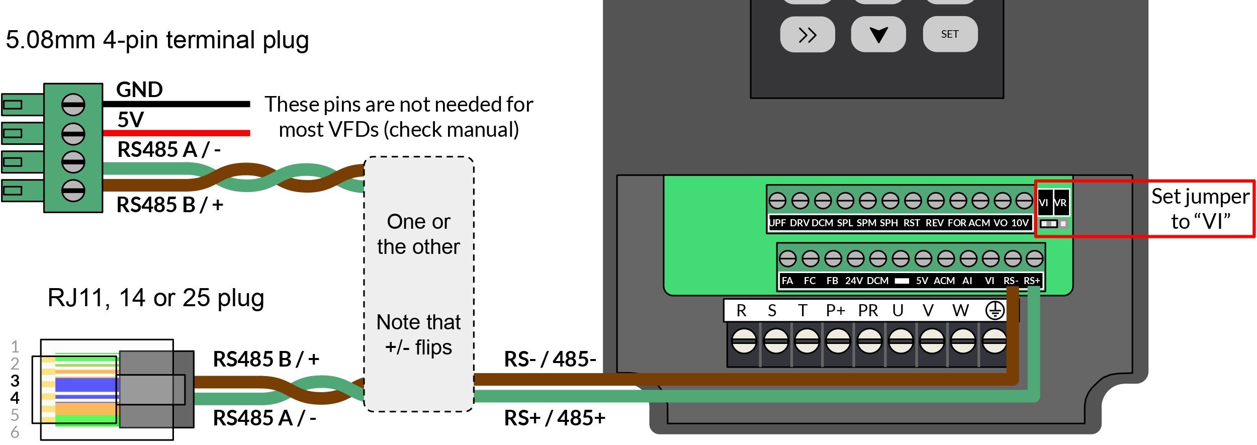
Note: if the VFD has a jumper to swap from controlling the spindle with the panel to using the wire signals, change this over. In the example below it’s the left 2 pins and called “VI”. Also, make sure your RJ cable has 6 positions or “6P” so it’s compatible to plug in. The RJ standard is a bit confusing and plugs that fall under RJ11, 12, 14, and 25 all seem to be compatible for hookup.
5V PWM Hookup
For the simple signals, use the 5-pin connector with GND, PWM, direction control, enable signal, and SaS (left-to-right, all 5V) and look for matching labels on your VFD like ‘PWM’ / ‘VI’, and ‘GND’ / ‘ACM’. If you plan to never run the spindle in reverse for tapping and reverse cutting, you can also make your life easier by wiring the VFDs ‘FOR’ pin to ‘DCM’ so the spindle always runs forwards when it’s turned on.
Some VFDs don’t accept 5V PWM, in which case you can either try setting up RS485 or you can pick up a ‘PWM to 0-10V Analog signal converter’ and use that to translate the 5V PWM the controller has to the ‘0-10V’ your VFD needs.
Note: if the VFD has a jumper to swap from controlling the spindle with the panel to using the wire signals, change this over. In the example below it’s the left 2 pins and called “VI”.
SLB/SLB-EXT Spindle Settings
The typical settings if you want the PWM simple signals as default will include:
- $9 PWM Signal
- Enable = on, RPM controls spindle enable signal = off
- $16 Invert spindle signals
- Spindle enable=on, Spindle direction = on, PWM = on
- $30 Maximum spindle speed
- 24000 RPM
- $31 Minimum spindle speed
- 7500 RPM
- $32 Mode of operation
- Normal
- $33 Spindle PWM frequency
- 1000 Hz
- $34 Spindle PWM off value
- 0%
- $35 Spindle PWM min value
- 0%
- $36 Spindle PWM max value
- 100%
- $395 Default spindle
- SLB_SPINDLE or PWM
- $520 Spindle 0 tool number start
- 0
Verify these, then power-cycle your board to make sure the changes take effect.
Spindle Guidelines
- The list of already supported VFDs is the Huanyang v1, Huanyang P2A, Yalang YL620, H-100, and GS20 as noted in https://github.com/grblHAL/Plugins_spindle/tree/master/vfd. That doesn’t mean selecting these is guaranteed to work, rather that they tend to work for those generic models.
- If your VFD isn’t listed or the other defaults aren’t working for you, you can select “MODVFD” to setup your own custom RS485 settings. Disconnect and reconnect in gSender to see these new settings. They’ll span $462-481 and include registers, command words, addresses – all values that you’ll have to consult your VFD manual for.
Remember that your VFD will also require some setup through its own button interface or sometimes require jumpers to be placed correctly - Remember you can set up more than one option, for example you can leave the Laser as your default ($395), set the PWM Spindle as your second option ($511), then RS485 as your third ($512)
- For more info, the letters next to each spindle in the dropdown indicates its abilities:
- V: Variable Spindle speed supported
- D: Spindle Direction (M4) supported
- S: Spindle at speed feedback supported
- L: Spindle can control a laser (requires laser mode to be enabled in firmware)
- I: Spindle PWM output can be inverted
- R: Range Locked (min/max not inherited from Config/firmware settings)
- So for example, “DIV” means you can swap spindle direction, invert output, and have variable speed on that specific spindle.
Find more information for VFD setup at https://wiki.printnc.info/en/electronics/vfd/config or https://github.com/grblHAL/Plugins_spindle/blob/master/vfd/
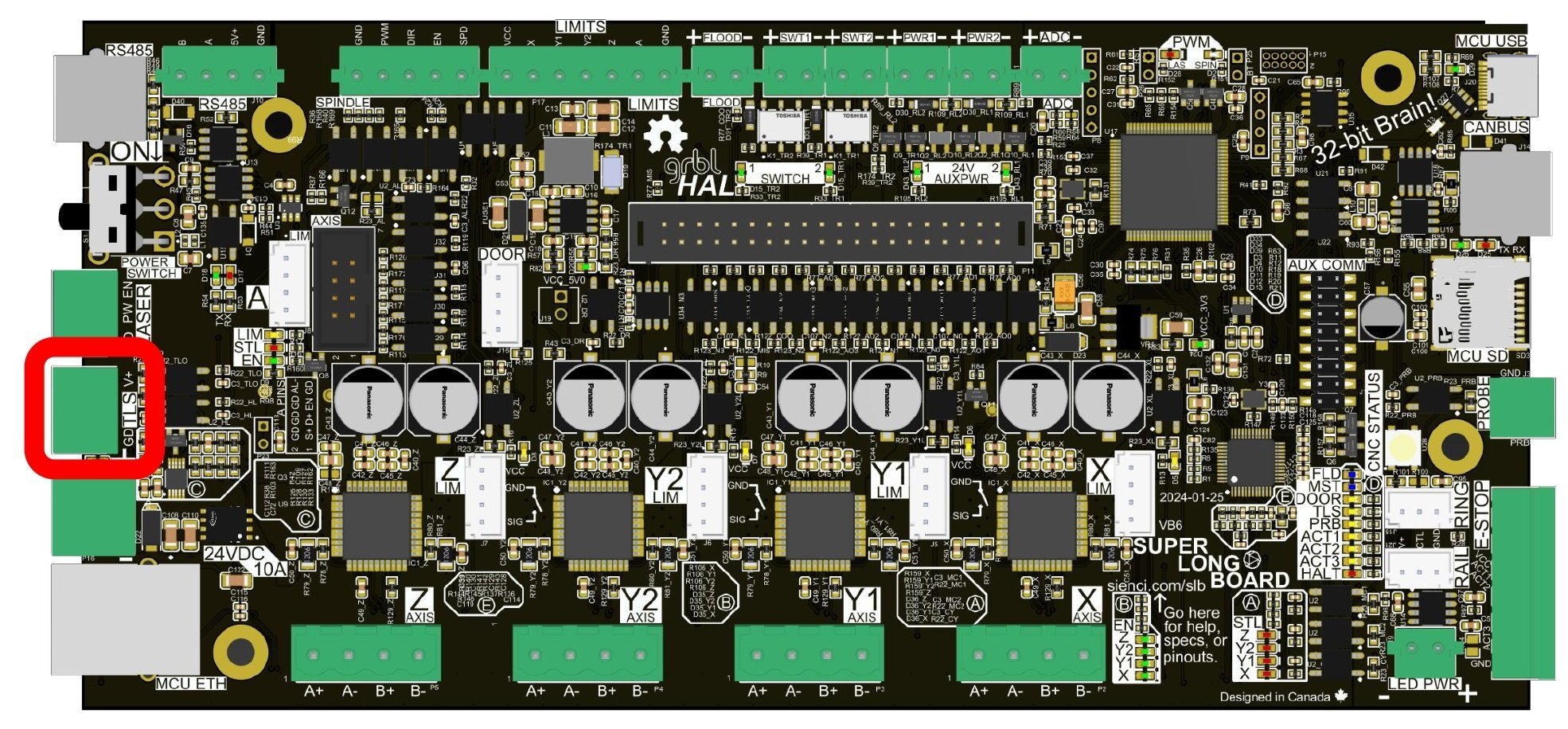
TLS
Short for “Tool Length Sensor”, this is a very common accessory for slightly more fancy CNC routers. Mounted somewhere the CNC can reach, they’re used as a reliable place to go to re-zero the Z-axis on jobs that require multiple tools/ tool changes. This is handy especially when your original Z zero is lost as the material is cut away. TLSs are typically NC (normally closed) switches so that if the wire gets cut the machine doesn’t crash into the sensor. The TLS output on the controller also provides 5V power for a powered TLS, the wire order being power, signal, GND (top-to-bottom).
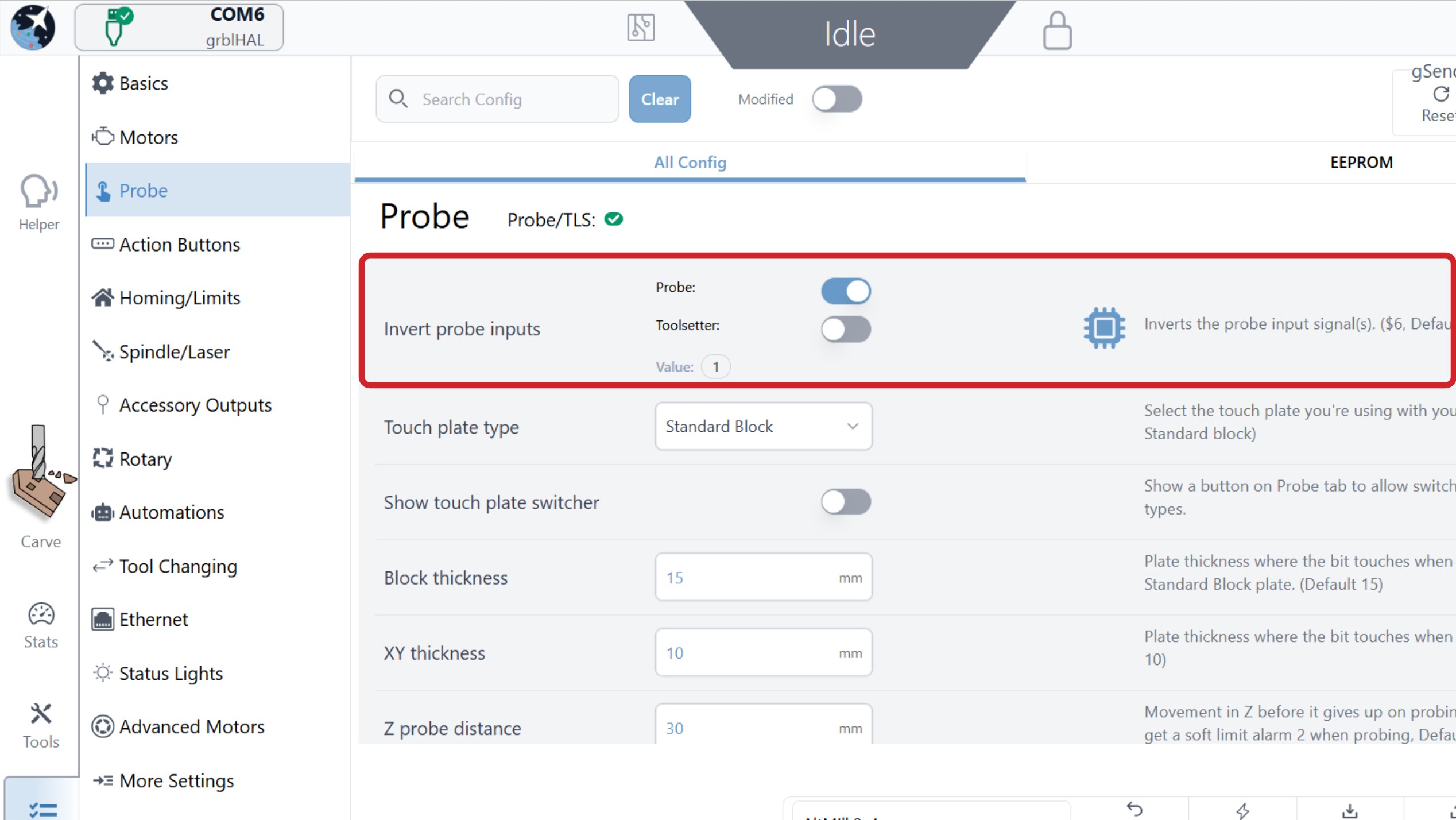
TLS Signal Inversion
If you have an NO-wired TLS, you must invert the signal before proceeding.
On gSender, in Config, go to the Probe heading. Find $6 Invert Probe Inputs, and toggle the Toolsetter option to the opposite setting. Press Apply Settings then turn OFF/ON the controller to have the setting take effect.
TLS Wiring
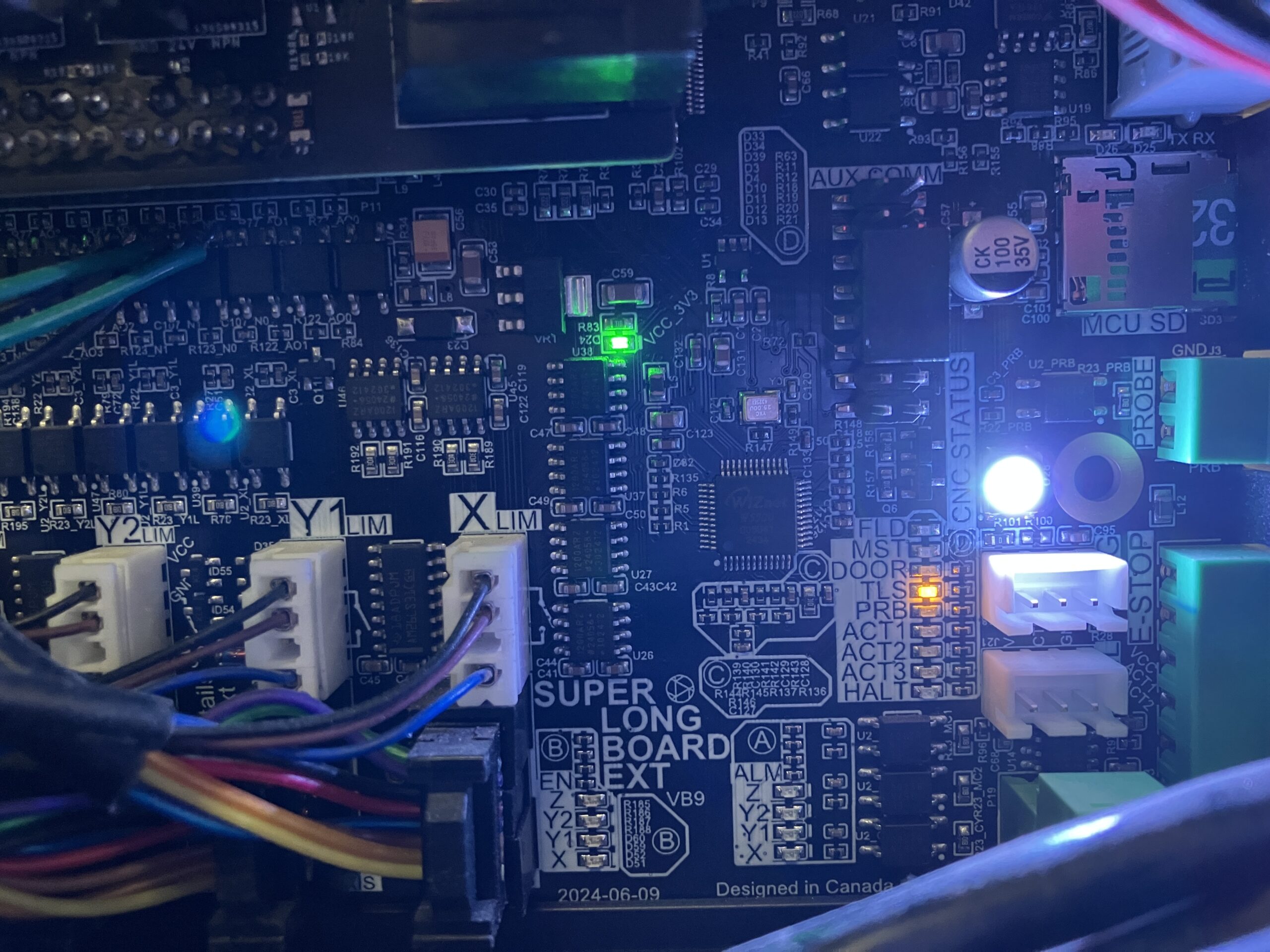
If your TLS is wired correctly, you should be able to press it and see the orange TLS light toggle ON or OFF on the controller.
- Orange light ON if TLS is wired NO
- The light will only be ON when TLS is pressed or disconnected
- Orange light OFF if TLS is wired NC
- The light will stay OFF if TLS is disconnected
If you’re unsure with your wiring or your TLS has more than 3 wires, you can use a multimeter and check any two wires until you find a set that contact/open when pressed, those two will be for signal and GND; the third might be power.
If you have 4 wires your TLS might have 2 switches, one that triggers when pressed down just a bit, then the next one pressed in case of over travel. This would typically trigger an E-stop or Pause but you only really have to use the one that triggers first.
TLS Testing
Check in your g-code sender if the TLS signal is set up correctly. This signal is shared with the touch plate, so the touch plate continuity or TLS press can trigger it. gSender has a status light to help see this, press the circuit board icon at the top of the screen. In other senders it should appear as ‘P’ for probe.
-
Press the TLS and check the Probe/TLS status light turns from RED to GREEN.
-
Contact the touch plate to the end mill on your machine (to get continuity) and check that it also turns from RED to GREEN.
-
If both the touch plate and TLS trigger the same response, then everything is working as expected.
See this documentation on how to set up tool changing (gSender tool changing feature) and make sure you select the ‘Fixed tool sensor’ option.
Rotary Axis
The SLB/SLB-EXT will still support anyone who already has a ‘switching’ rotary axis setup, like the A/Y Switch we launched our Vortex Rotary Axis with, in the same way that older grbl boards do. We wanted to preserve this functionality for easier backward-compatibility with older setups, plus making the switch to full 4-axis cutting has the extra cost of an external driver and some wiring despite some of the benefits that it offers.
The main improvements to how SLB/SLB-EXT handles rotary switching is:
- The A-axis values for steps/deg, maximum speed, and acceleration ($103, $113, and $123) are now stored directly on the SLB/SLB-EXT instead of relying on gSender settings
- This will help maintain correct values across computers, since every time gSender is switched into rotary mode it can just swap the A-axis values and the Y-axis values, then swap them back once you leave rotary mode
- Hard and soft limits can now be left on while in rotary mode
- This is new from grblHAL, where when the maximum travel of any axis is set to 0, it’s able to rotate infinitely while leaving hard and soft limits on for all other axes
For anyone who isn’t already familiar, ‘rotary switch’ setups were created so that people with typical 3-axis CNCs (X, Y, Z), could move on to more advanced rotary carving (X, Z, A) by swapping or mechanically switching Y-axis movements and limit switches over to an A-axis since typical grbl boards can’t run more than 3 axes at a time. This setup also has some other requirements:
- A g-code sender that can convert and display rotary axis files, and ideally store and swap grbl settings between the Y and A-axes (gSender accomplishes this)
- A CNC that’s set up to hold itself in place in the Y-axis while cutting with the A-axis, either using clamps or in the case of the LongMill it relies on the friction and mechanical advantage in its lead screws
You can read more about how this control works and our approach in this article.
4th/A-axis
The SLB/SLB-EXT is able to support an extra fourth, fully independent cutting axis too. This rotary “A-axis” is set up to run along the width (X-axis) of your CNC and has some advantages over a typical ‘rotary switch’ setup:
- The Y-axis motors can stay powered while cutting, meaning they can hold their position for more accurate cutting and not rely on lead screw friction clamping the CNC’s Y-axis
- There’s no ‘changeover’ process which saves you time and mistakes since you don’t need to swap back to realign the rotary, or bother with toggling switches or changing settings
- If you’re ready to dive in, you can generate much more complex and efficient cuts using all 4 axes of movement and creating even more impressive projects
If you set one of these up yourself, you can either check out our Vortex rotary axis with a pre-made wiring loom and closed-loop NEMA 23 with a built-in driver that you can use for your own rotary setup or upgrade your existing open-loop Vortex, or you should pick up your own independant motor driver. Most motor drivers on the market will do like a DM542 or TB6600 but use your best judgement and be mindful of who you buy from.
The main downside of this setup though is that most hobby CAM software is yet to catch up to the hardware and support 4-axis toolpaths. This means that you’ll either still use it for 3-axis cutting (alongside some of the benefits mentioned above) or you’ll have to get creative in finding a solution that works for you by manually modifying code, using indexing, or paying for a more expensive CAM software. At this time we have only tried Snapmaker’s Luban software, though we’ll update this section once we have more to recommend.
Driver Wiring
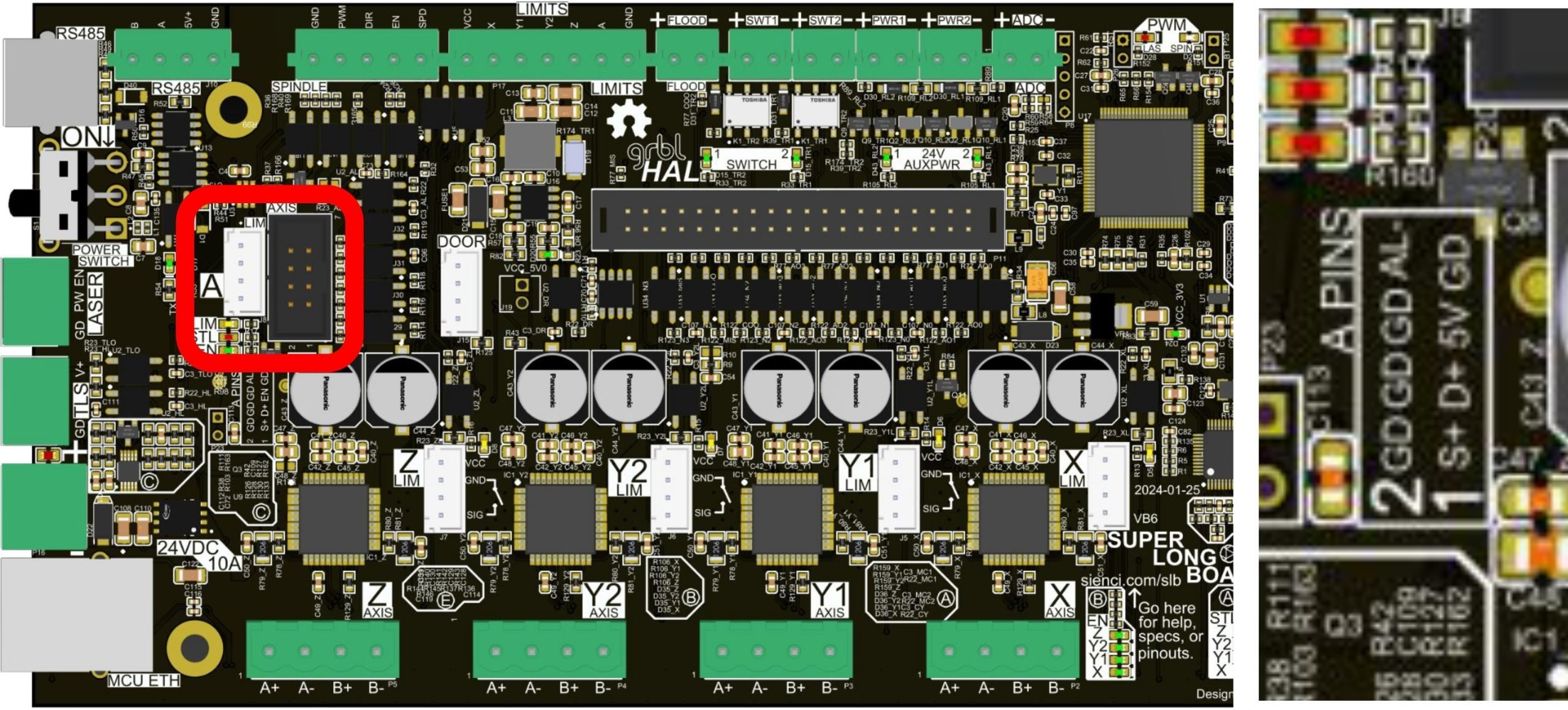
This takes the form of two independent plugs labelled for an “A-axis”, where you can plug in your:
- Motor driver to the drivers signals on the SLB/SLB-EXT (black plug)
- A-axis limit switch (white plug), and
- Additional power supply to your motor driver
Any motor driver that can be driven by Step/Dir common-cathode arranged signals will work as long as it’s rated for the stepper motor you’re planning to use. The black connector is a “Female IDC Flat Ribbon Cable Connector, 8 pins, 2 Row, 2.54mm Pitch”, but you can also use any 2.54mm spaced connector cables. Also if your limit switch doesn’t have a JST connector, you use the terminal connector ‘Limits’ A-axis output.
- https://www.digikey.ca/en/products/detail/adam-tech/FCS-08-SG/9832361
- https://www.amazon.ca/Elegoo-120pcs-Multicolored-Breadboard-arduino/dp/B01EV70C78/
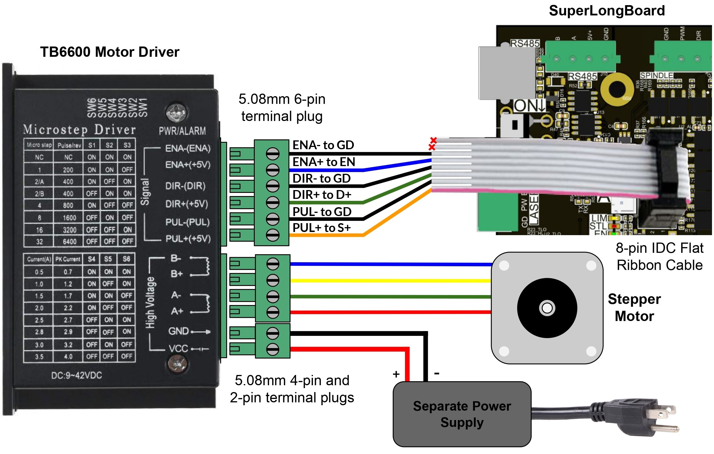
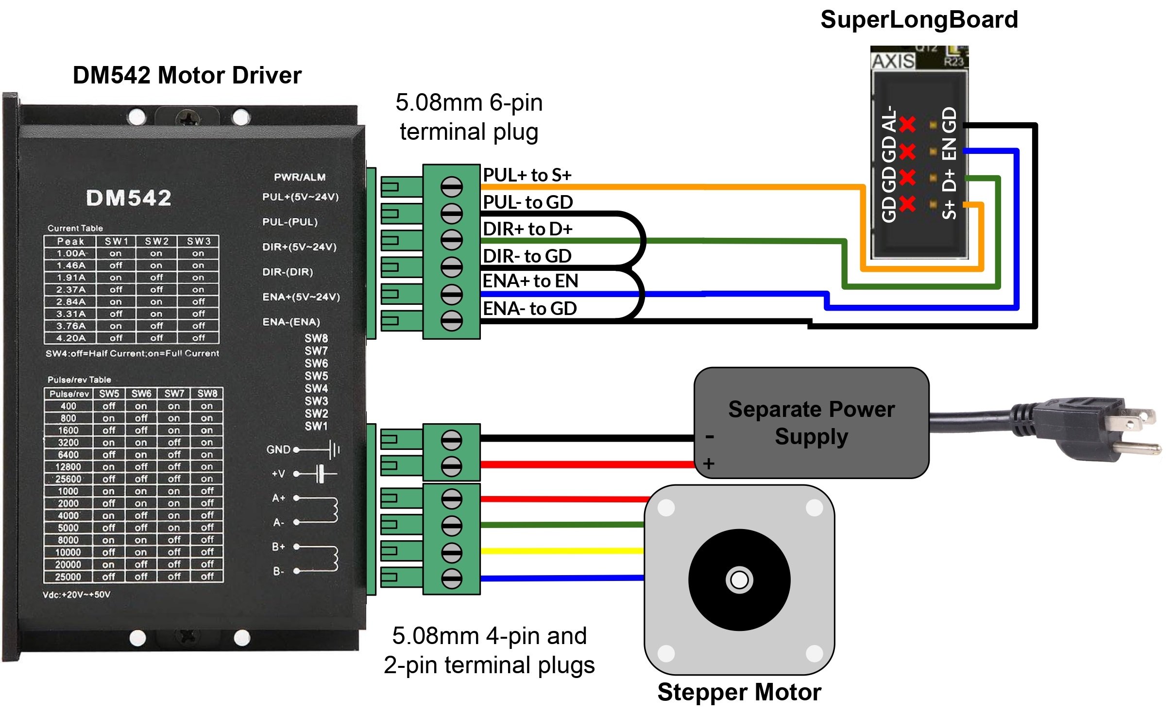
Below we’ve illustrated two examples that you can use to better understand how to create your own setup. One shows the TB6600 driver and uses the IDC connector with all the available connections running to the SLB/SLB-EXT. The other has the DM542 driver hooked up with single-wires and bridging between the ground pins. Either hookup method is fine no matter the driver, just note that different drivers will have their outputs in different orders. The drivers will also require you to use an appropriate power supply, manually configure the DIP switches for current or holding current, as well as set the microstepping (most times we’d recommend 1/8th).
- D+ goes to DIR+
- S+ goes to STEP+ or PUL+
- 5V goes to EN+ or ENA+
- GD goes to the Driver ground pins like DIR-, PUL-, etc.
- AL- likely won’t be supported by your driver, but is an active-low alarm signal for the motor driver to tell the board if something has gone wrong similar to the E-stop
Once the wiring is complete, in your g-code sender check that the rotary is moving at the speed, distance, and direction you’d expect and that the limit switch is working if you have one. If there’s anything wrong you’ll want to check your typical A-axis settings for movement ($2, $3, $4, $37, $103, $113, $123, $133, and $376) and for homing/limits ($5, $18, $23, $44, $45, and $46).
Cut & Experiment
If you’re happy that your rotary is turning successfully, feel free to try out some sample 4th axis files we made to test how your setup is working. Some things to keep in mind to carve these sample files successfully:
- They both use an 1/8″ tapered ball nose, cut out of wood 1″ diameter, with minimum 40mm long
- Make sure that A-axis direction is set correctly so that Positive A has the cylinder turning towards you
- Since there’s no roughing pass, use the speed override to start off the file slowly (10-30%) during the initial plunge so you don’t accidentally break the bit, once the plunge is done you can turn the speed back up for the rest of the job
- Small Lion Statue: https://drive.google.com/file/d/1I15FD8WIJoty8UhpEh17H04MH2VqPr3M/
- Knight Chess Piece: https://drive.google.com/file/d/156eTQ1c2pt6jm9ehI4Adu6OitGL33CJs/
If you’re ever running into a situation where clicking “Zero A” in gSender sets the value to 0.01 or 0.02 instead of zero, this is a known bug with grbl and grblHAL where the location doesn’t get reported back from the machine correctly, but the location is definitely being set to zero. This can be a little stressful to see but unfortunately we don’t have the ability to fix it ourselves.
You can also learn more about how some of this works by checking out Part 1 and Part 2 of these user-made videos by SparksTech!
Tips for Luban A-axis CAM
Download it here: https://www.snapmaker.com/en-US/snapmaker-luban
- Select “link” as the carve option inside Luban, otherwise you’ll just get 3-axis movements
- Remember to define the shape of your tool
- After you export the code, open it in a text editor to:
- Remove the default header since it contains some Snapmaker-specific M-codes that grbl doesn’t support
- Check the first Z-movement to make sure there are no unexpected plunges
- Do a find and replace to change X into Y; then Y➜X; then B➜A. The rotary on the Snapmaker machine is lined up along the Y-axis, so you need to switch it to be along the X-axis.
Enclosure Mounting
You can mount your SLB/SLB-EXT however you like. Some factors to consider might be your machine setup, computer location, if you have an enclosure, or if you want to access other things or see the pretty lights on the board. The most versatile way is the 4 holes on the enclosure which will allow you to mount it to any flat surface, but if you have a LongMill MK2 you also have the option to mount it directly to your Y-axis rail.
Some of the extra tools you’ll need:
- Bolting to MK2 Rail – M5 Allen wrench, plus grab the hardware and bracket provided with the SLB
- Screw Down / Flat Mounting – 2 to 4 wood screws (minimum size #4 or ¾” and min length of ½”) plus the necessary screwdriver or bit driver
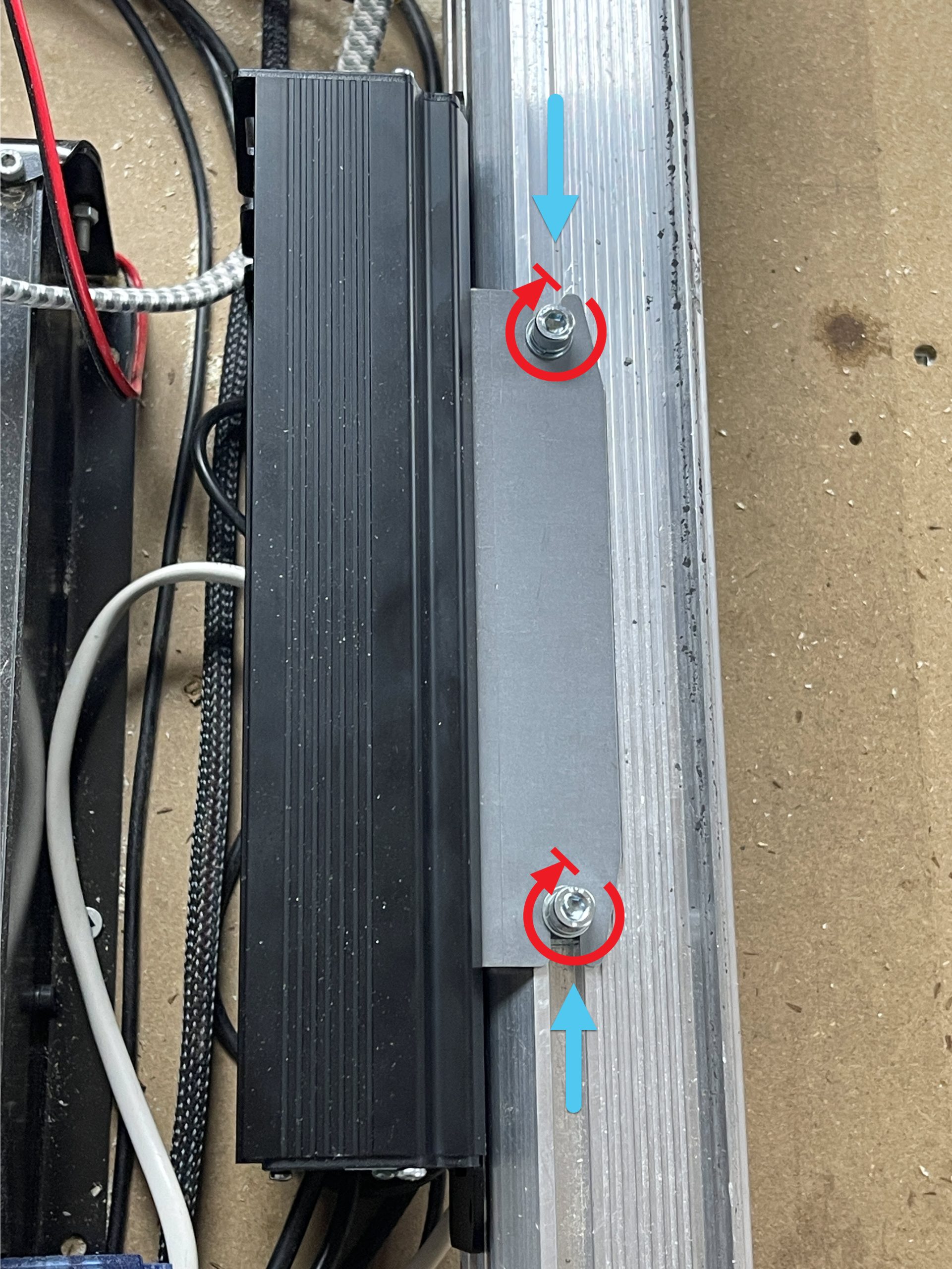
Bolt to Rail
For rail mounting, slide the two T-nuts onto the track above the left Y-rail and loosely thread on the two M5 bolts. You may need to remove your limit switch on MK2’s temporarily to enable the nuts to be slid into the rail.
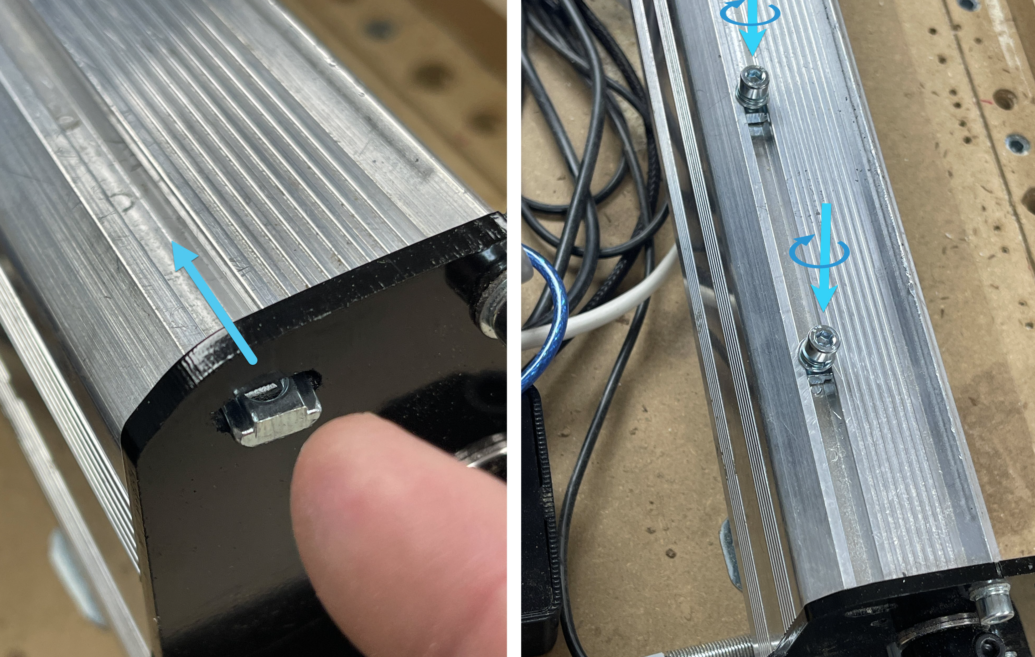
Insert the sheet metal bracket into the slot at the back of the enclosure. The bracket will feel loose for now so you’ll want to hold it in place until the next step.
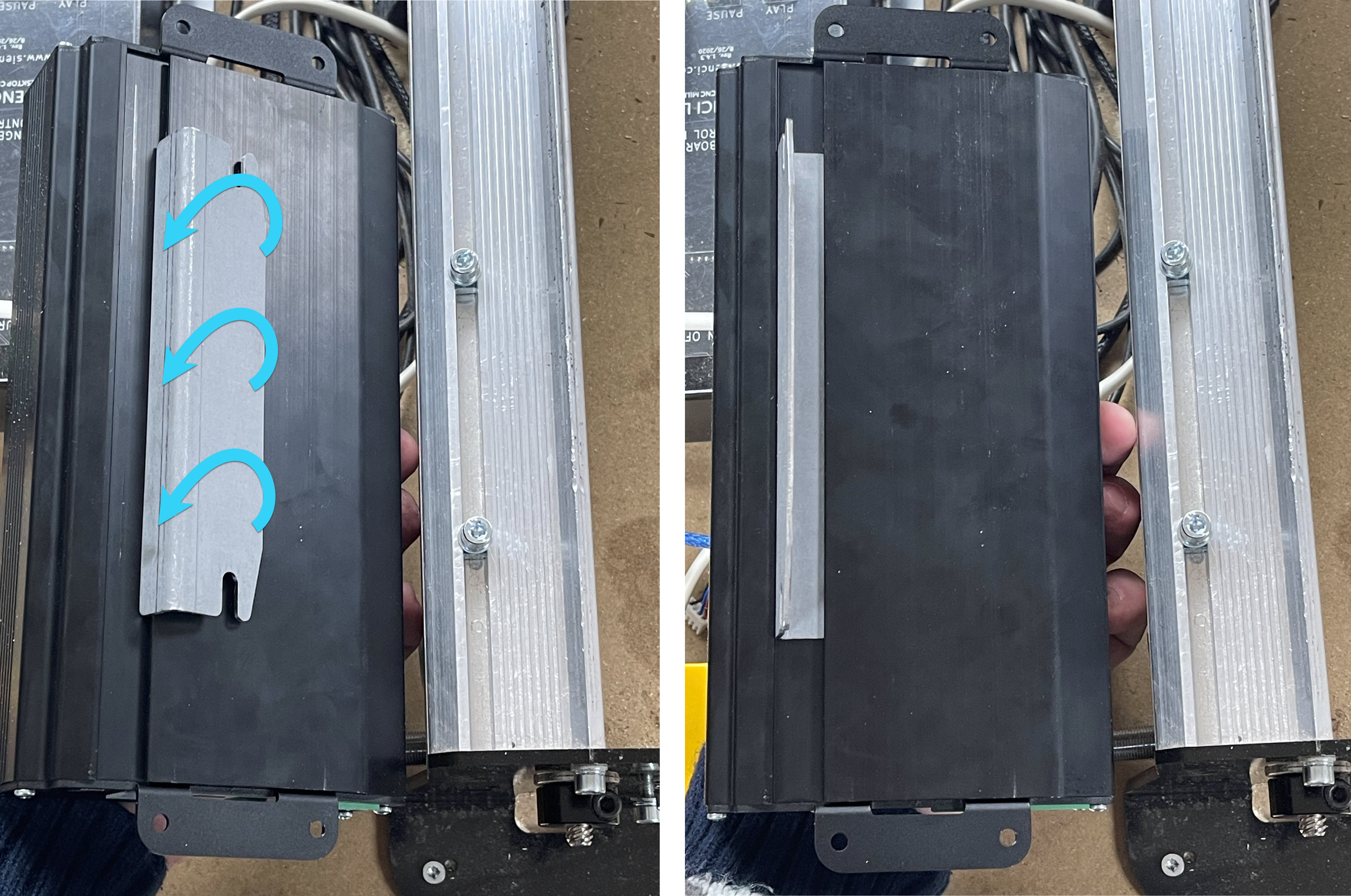
Place the bracket-enclosure assembly onto the Y-rail and slide the two screws into the slots in the bracket, then tighten the two screws with an Allen key to lock the entire assembly onto the rail.
Screw Down
You can mount your controller flat on your wasteboard next to your machine, or even on the side or at the back of your workstation. You can also hang the controller vertically. The enclosure has been designed with reasonable consideration for dust penetration and vibration, but if you are a more cautious person you can feel free to mount the box further away from your CNC.
When placing your SLB/SLB-EXT on its own or among other CNC control electronics, consider that most wires are designed to route out the backside of the enclosure with the exception of a handful of more typically accessible plugs on its front like the E-stop and USB.
It’s easy to use the enclosure as a template to mark and drill the holes. The holes are 4.5mm large, spaced 45mm from each other and 230mm from the opposite pair. They’re not perfectly centered on the box but close to it.
You can use whatever bolt or screw type you like but the easiest approach is to use a minimum of 2 countersunk wood screws on diagonal holes from size #4-#8 and a minimum length of ½”. You might have to remove some of the plugs on the ends to access the holes when you screw down the enclosure.
Technical Reference
Connectors List
The SLB/SLB-EXT comes with many inputs and outputs that are easy to wire in for CNC customization and accessory hookup by using pluggable terminal connectors. There are also a handful of other connectors used that are common and widely available for purchase. Below lists all connectors used on the board (male) with example links:
- Power in: 2-pin 5.08mm pitch Pluggable Terminal Block (x1)
- Motors:
- SLB: 4-pin 5.08mm pitch Pluggable Terminal Block (x4)
- SLB-EXT:
- Signal: 2×4-pin 2.54mm pitch Female IDC Flat Ribbon Cable Connector (x4)
- Power: 2-pin 3.81mm pitch Pluggable Terminal Block (x5)
- E-stop, AUX Limits: 7-pin 3.81mm pitch Pluggable Terminal Block (x2)
- Touch Plate, Flood out, Switch, Aux Power, LED Power, ADC: 2-pin 3.81mm pitch Pluggable Terminal Block (x8)
- RGB LED Strips: 3-pin 2.5mm JST XHP (x2)
- XYYZA Limit Switches, Door: 4-pin 2.5mm JST XHP (x6)
- Laser, TLS: 3-pin 3.81mm pitch Pluggable Terminal Block (x2)
- Spindle: 5-pin 3.81mm pitch Pluggable Terminal Block (x1)
- RS485: 4-pin 3.81mm pitch Pluggable Terminal Block (x1)
- Aux Spindle, Pendant: RJ25 Phone Jack
- A-axis: 2×4-pin 2.54mm pitch Female IDC Flat Ribbon Cable Connector (x1)
- AUX COMM Header: 40-pin 2.54mm pitch GPIO Cable (x1)
If you don’t happen to have these specific connectors on hand there are also common ‘hookup wires’ that ship with many electronics or Arduino kits that are 2.54mm pitch that you could also use to make many of the above connections.

Current Unused SLB Ports
Right now there are a handful of plugs and pins on the SLB/SLB-EXT that technically don’t do anything useful yet which is why there’s nothing in the manual on it. The idea was that by adding in the hardware at the start, we could keep working on testing and implementing firmware to make more features available to all SLB/SLB-EXT owners without having to buy a new board. We’re very excited about it but ultimately can’t make any guarantees on what will and won’t ultimately work, so that’s why no features have been promised yet outside of what’s already been tested and delivered. These ports include the: SaS Spindle pin, Pendant, SD card, Door, ADC, 40-pin AUX COMM Header, and AUX IO Header.
If you’re still interested in trying these out without our support or documentation, we have all our board designs and firmware code available online for reference and modification so you can feel free to try your own stuff and even contribute back to the project! For instance, you can see the 40-pin inputs and outputs in the full schematic PDF on page 19.
SD Card Macros
Though this isn’t yet supported in an official firmware build, you do have an option to try it out experimentally. Find the link here: https://forum.sienci.com/t/auto-squaring-on-the-slb/13753/20
This feature allows you to run complex macros with variables and math from an SD Card inserted into the controller’s SD card slot. Once you flash the firmware, the remaining steps are to:
- Make a plain text file with standard g-code and/or variables and controls supported by grblHAL
- End the file with
M99 - Name the file with a letter and three numbers, and “.macro” as the file extension, e.g.
P101.macro - Save it on the SD card then put it into the SLB and power cycle the board
- In this example, the g-code command
G65 P101will now run the macro on the SD card