
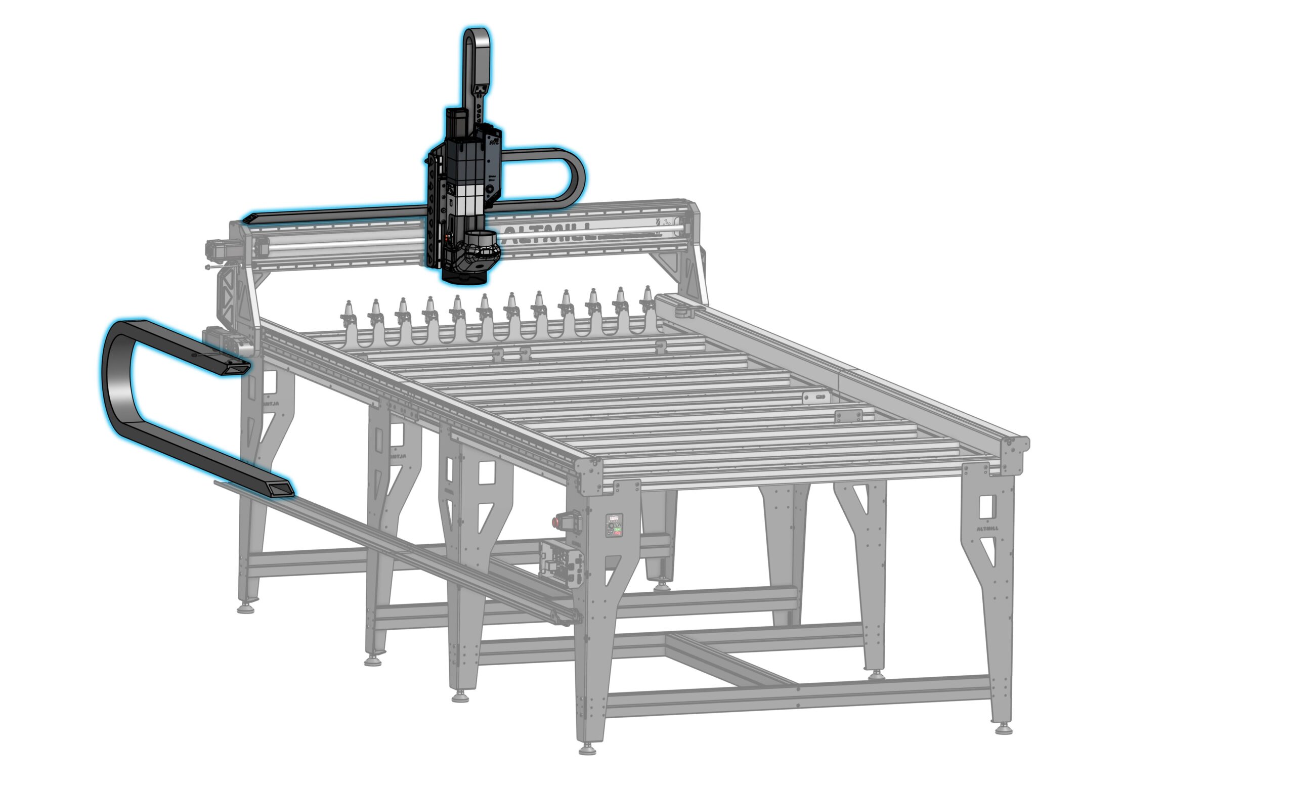
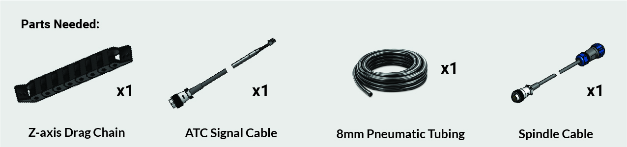
Spindle Installation & Drag Chain Setup
Spindle & Drag Chain Arm
-
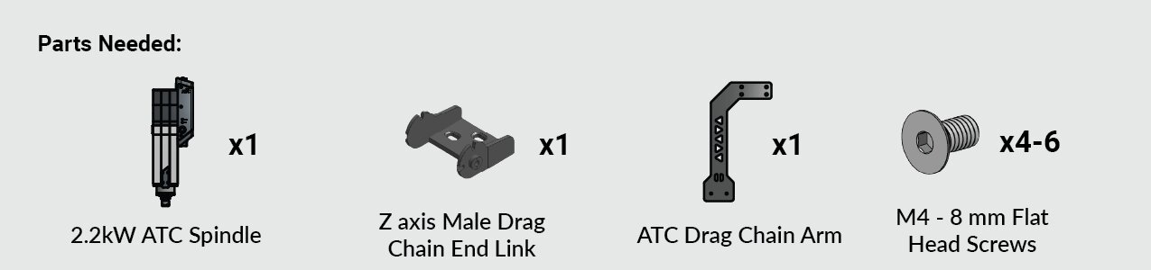
Start by unpacking the ATC spindle and grabbing the ATC drag chain arm. We will also need 6 x M4 – 8mm flat head screws and the Allen key from the ATC fasteners bag.
-
Lift the spindle out of the bottom foam and place it on the top foam packaging with the threaded mounting holes facing up.
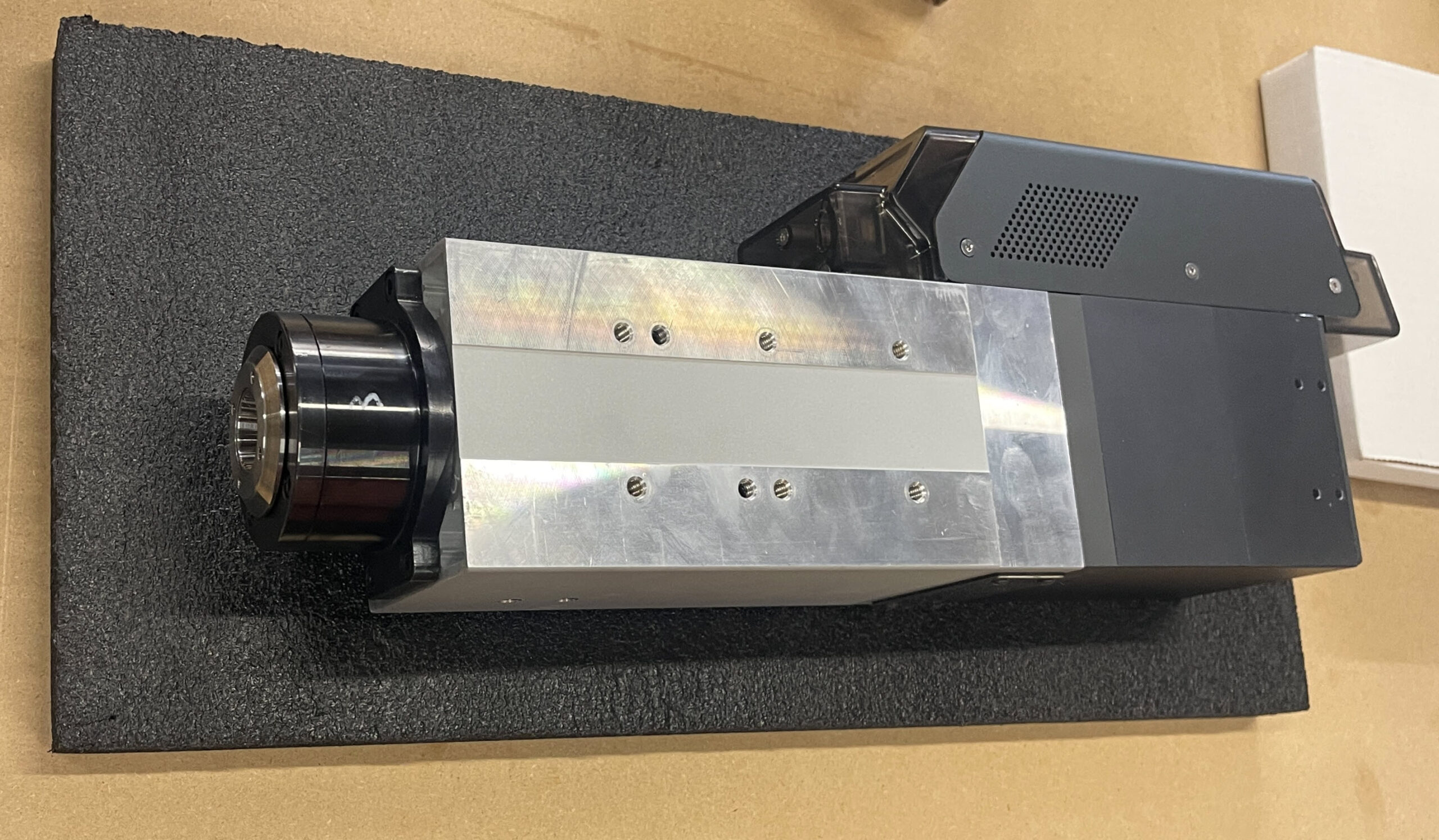
⚠️ Never stand the spindle on its nose (tool end) to avoid damaging the bearings. -
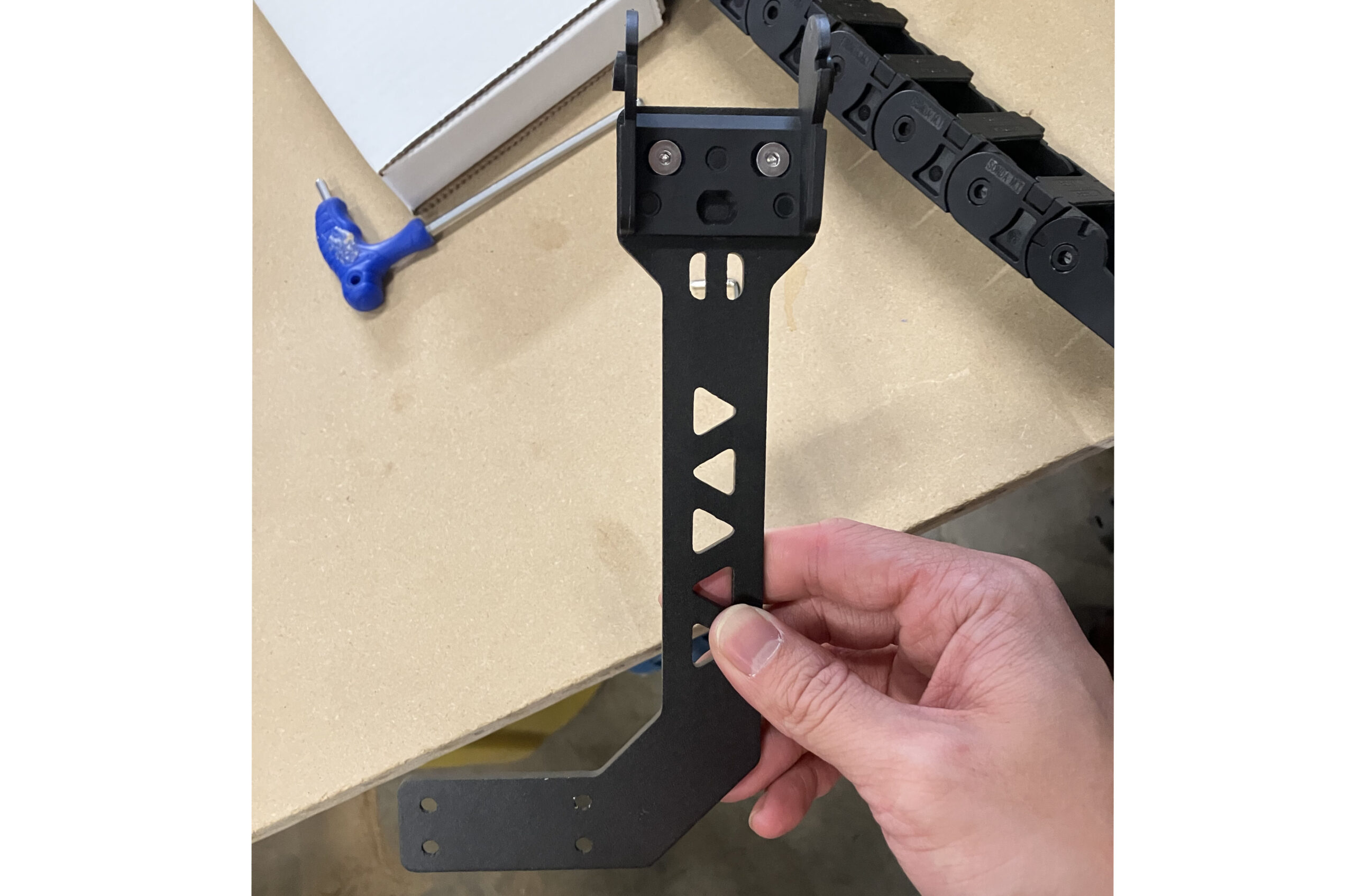
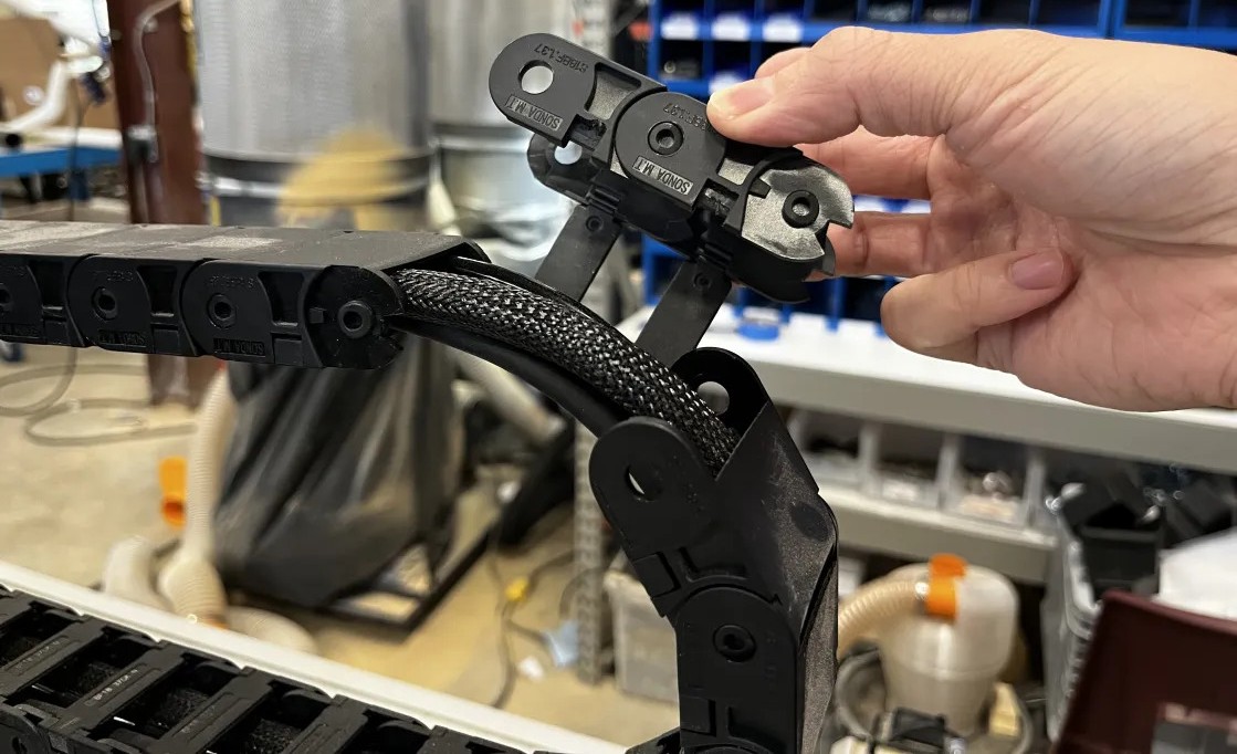
Remove the male end link (studded end) from the Z-axis drag chain.
-
Attach this end link to the ATC drag chain arm, minding the mounting position and direction, using two (2) M4 – 8mm screws.
-
Mount the drag chain arm to the spindle using four (4) M4 – 8mm screws.
Mounting Plate

-
Place the ATC mounting plate onto the spindle.
-
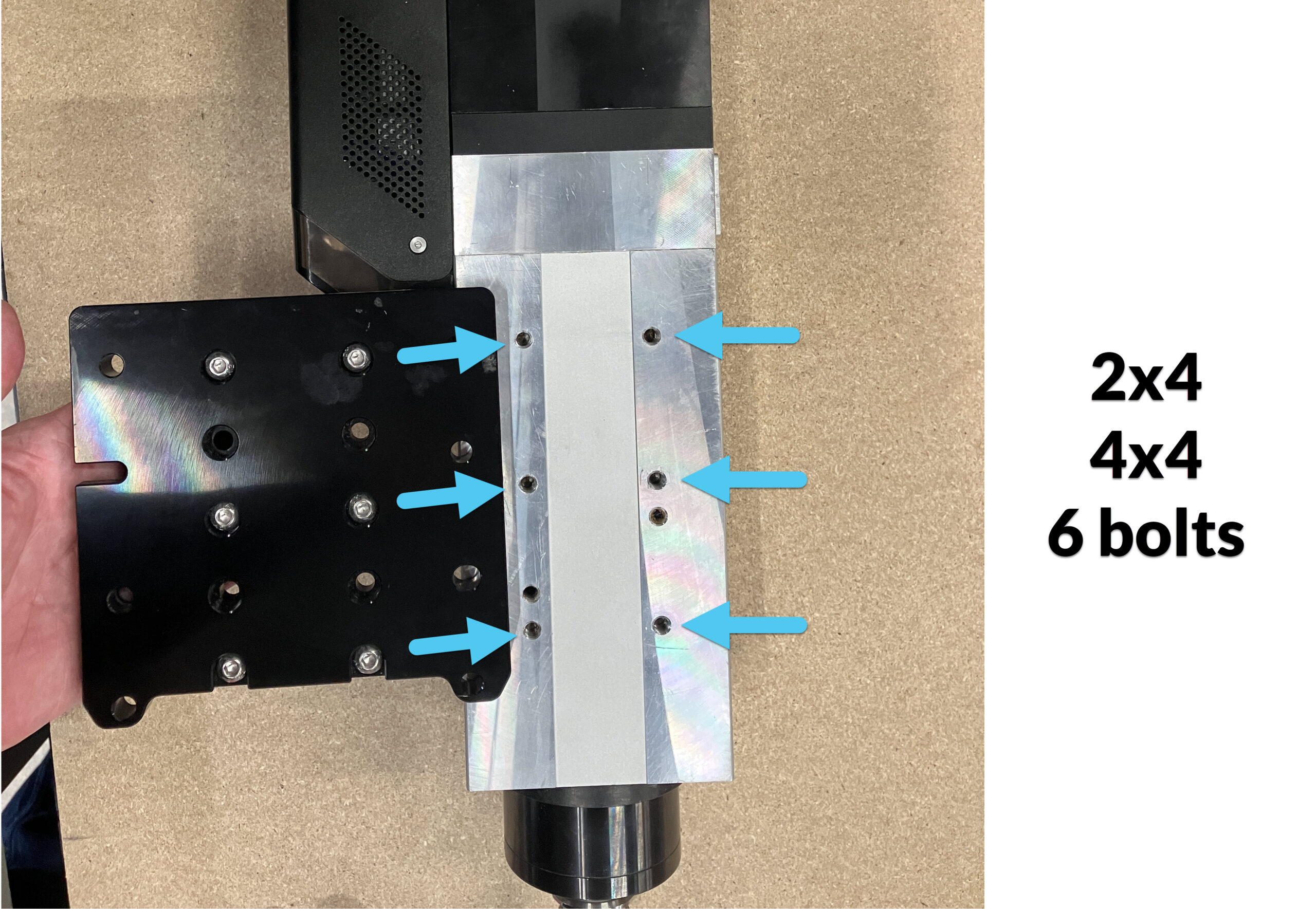
Select the correct mounting position based on your machine configuration.
4×4 & 2×4 Machines the standard configuration is the center position. The mounting plate holes should align up with six (6) corresponding holes on the spindle.
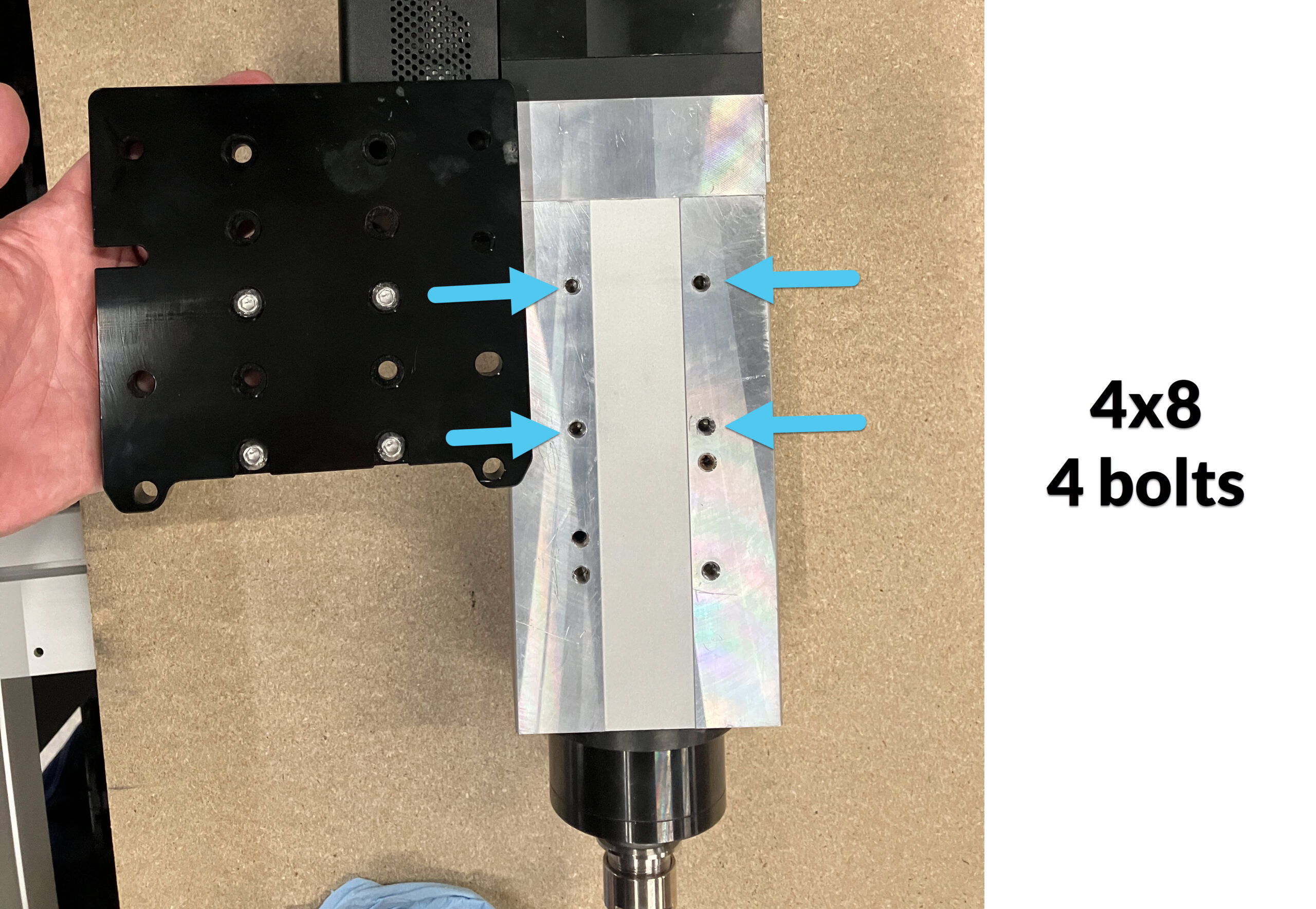
4×8 Machines the mounting plate should be shifted up. The mounting plate holes will align with the top four (4) holes on the spindle.
-
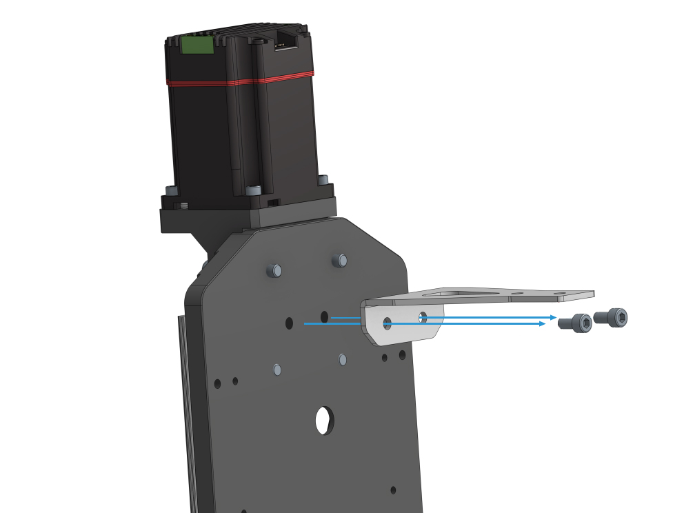
Secure the mounting plate using M6 – 14mm button head screws.
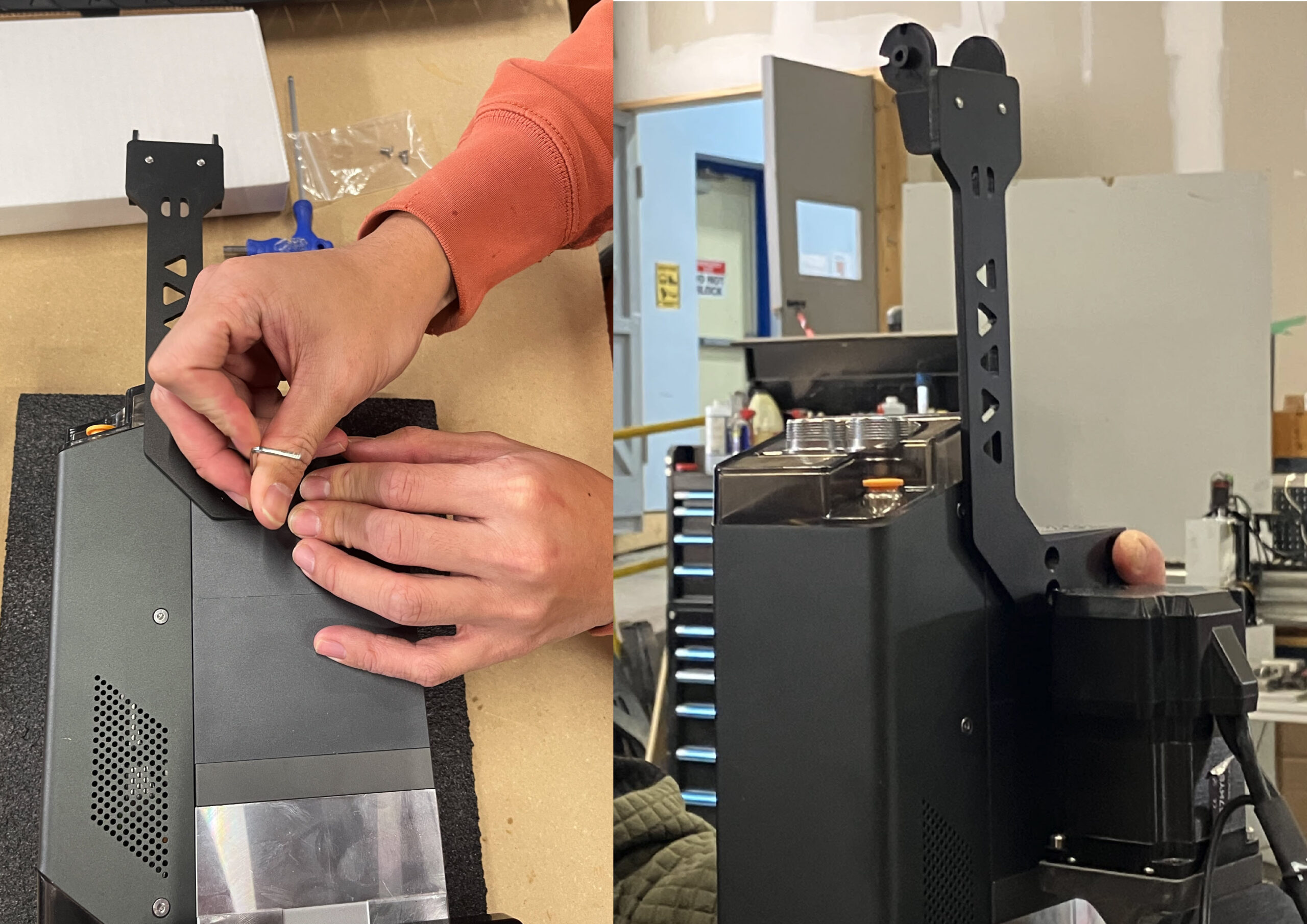
Mount the Spindle
⚠️ Due to the weight, we recommend two people to mount the ATC spindle.Identify Your Gantry Plate
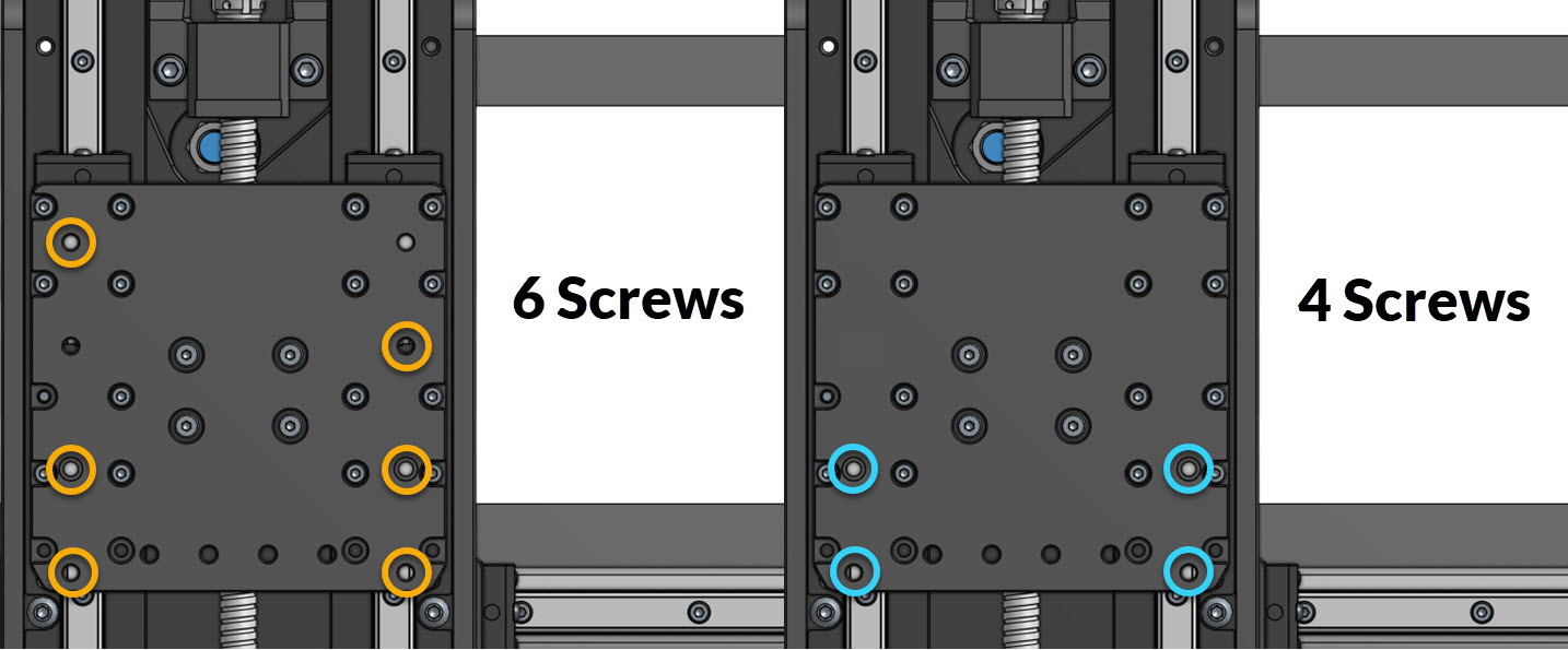
Look at your Z-gantry on your AltMill and compare to the image below.
If your Z-gantry has the orange circled hole pattern, follow the 6 Screw Installation.
If your Z-gantry has the blue circled hole pattern, follow the 4 Screw Installation.
Mount the Gantry
6 Screw Installation
Most newer machines should have this hole pattern in the gantry. For improved stability, we recommend this installation if you have the gantry for it.
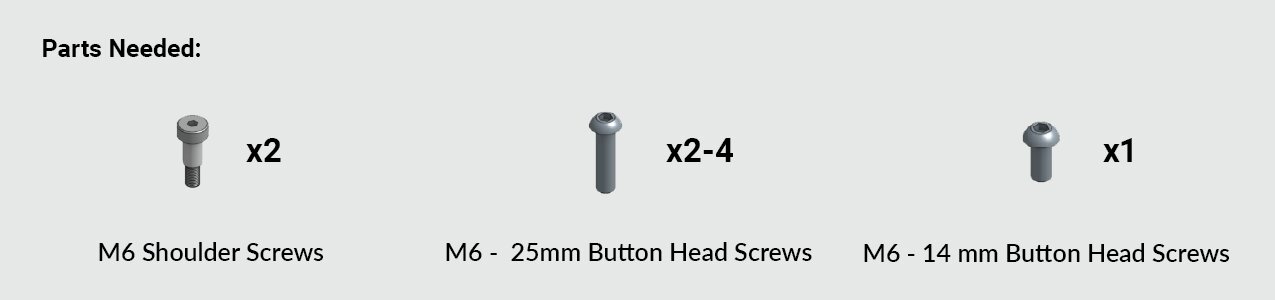
Grab:
-
Two (2) M6 shoulder screws
-
Three (3) M6 – 25 mm button head screws
-
One (1) M6 – 14 mm button head screw
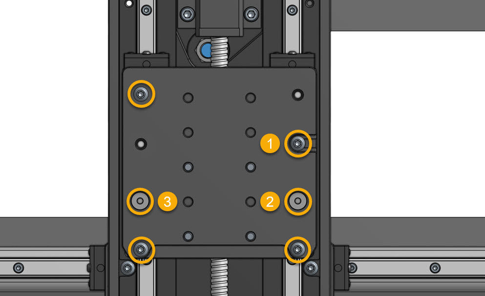
- Thread the M6 – 14 mm screw into the hole (marked #1) in the image below. Leave about 7 mm (1/4 in) sticking out. Hang the ATC spindle on this screw using the mounting slot. This acts as a temporary anchor — do not tighten.
- Install the two (2) M6 shoulder screws in the lower holes, marked #2 and #3. Start by hand, then tighten fully, in the order listed.
- Install the two (2) M6 – 25 mm button head screws in the lowest mounting holes. Start by hand, then tighten fully.
- Install the final M6 – 25 mm screw in the upper left hole, and tighten it fully.
4 Screw Installation
Grab:
-
Two (2) M6 shoulder screws
-
Two (2) M6 – 25 mm button head screws
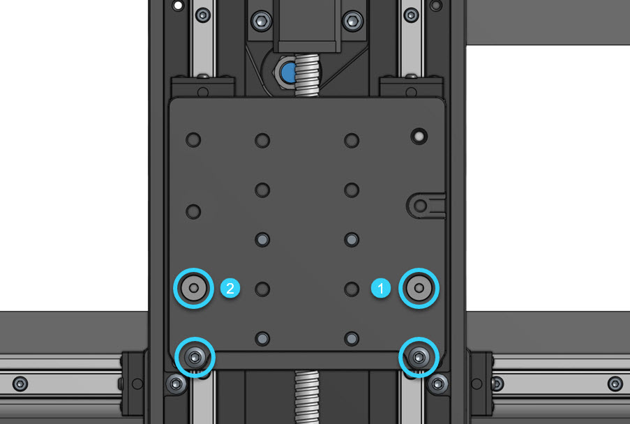
- Hold the ATC spindle against the X-axis gantry. Install the two (2) M6 shoulder screws in the lower holes, marked #1 and #2. Start by hand, then tighten fully.
- Install the two (2) M6 – 25 mm button head screws in the lowest mounting holes. Start by hand, then tighten fully.
Drag Chain Hardware Installation
This section will modify the 4×4 and 2×4 AltMills to make them compatible with the Z-axis drag chain.
4×8 Machines
SKIP AHEAD TO CABLE AND TUBING ROUTING
4×4 & 2×4 Machines
Remove the Drag Chain Bracket
- Disconnect the X-axis drag chain from its end link on the bracket.
- Remove the old drag chain bracket from the back of the gantry.
-
Separate the one (1) end link from the old drag chain bracket, we will use it.
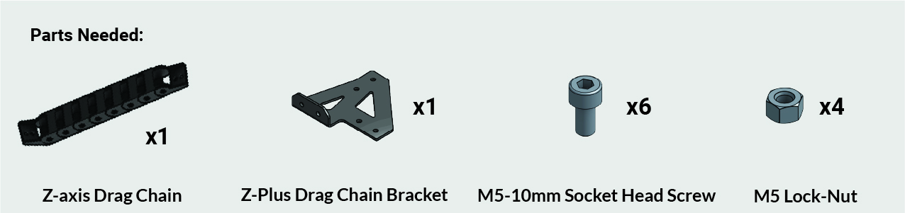
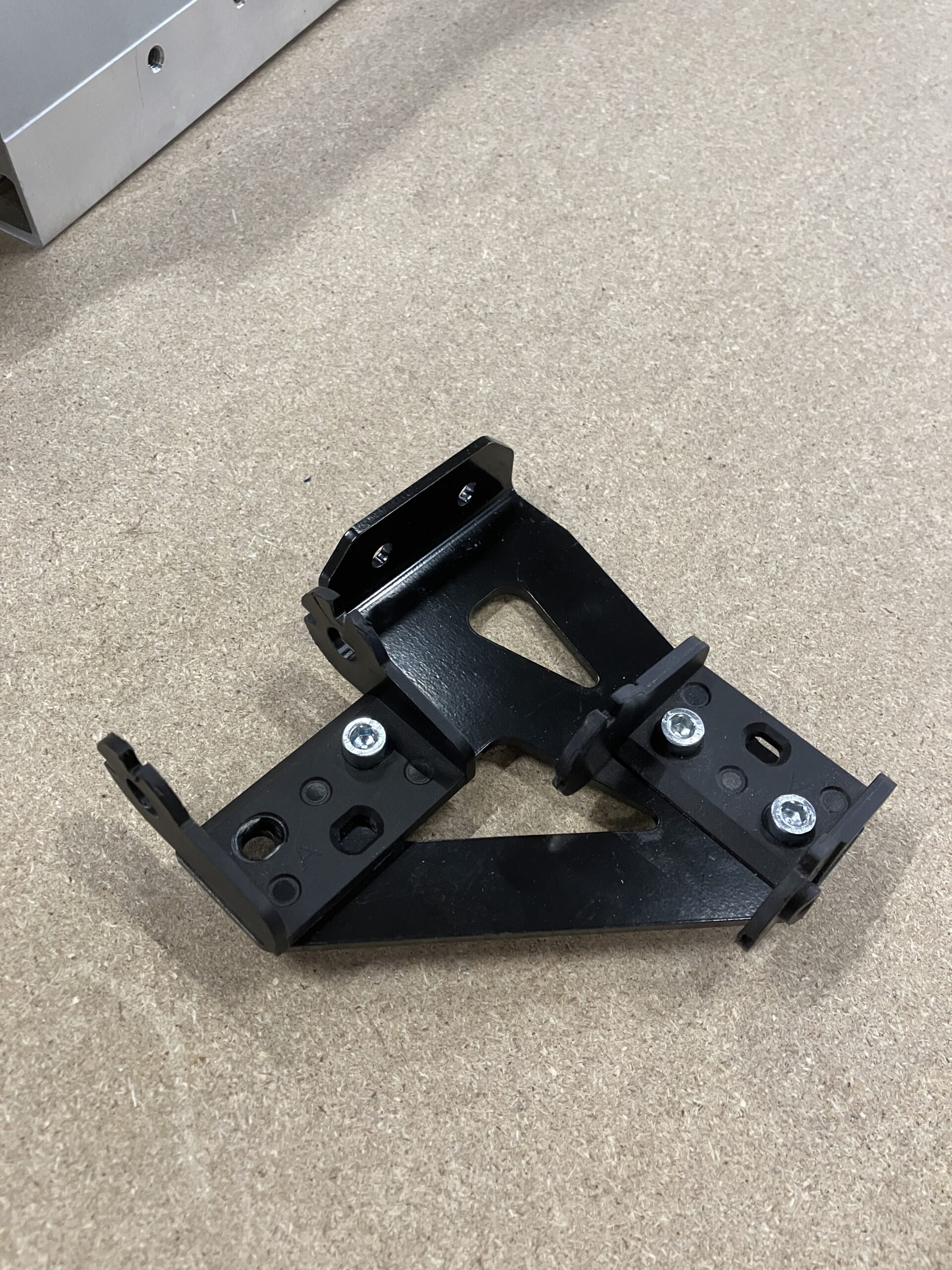
Install the Z-Plus Drag Chain Bracket
-
Remove one (1) end link from the Z-axis drag chain
-
Install the two (2) end links on the new Z-plus drag chain bracket, by using M5 – 10mm screws and M5 lock nuts. Only use 3 of each for now, to ease cable routing later on.
Tip: Ensure the male and female drag chain ends are correctly oriented; reversing them is tedious.
-
Install the Z-Plus drag chain bracket back onto the XZ carriage.
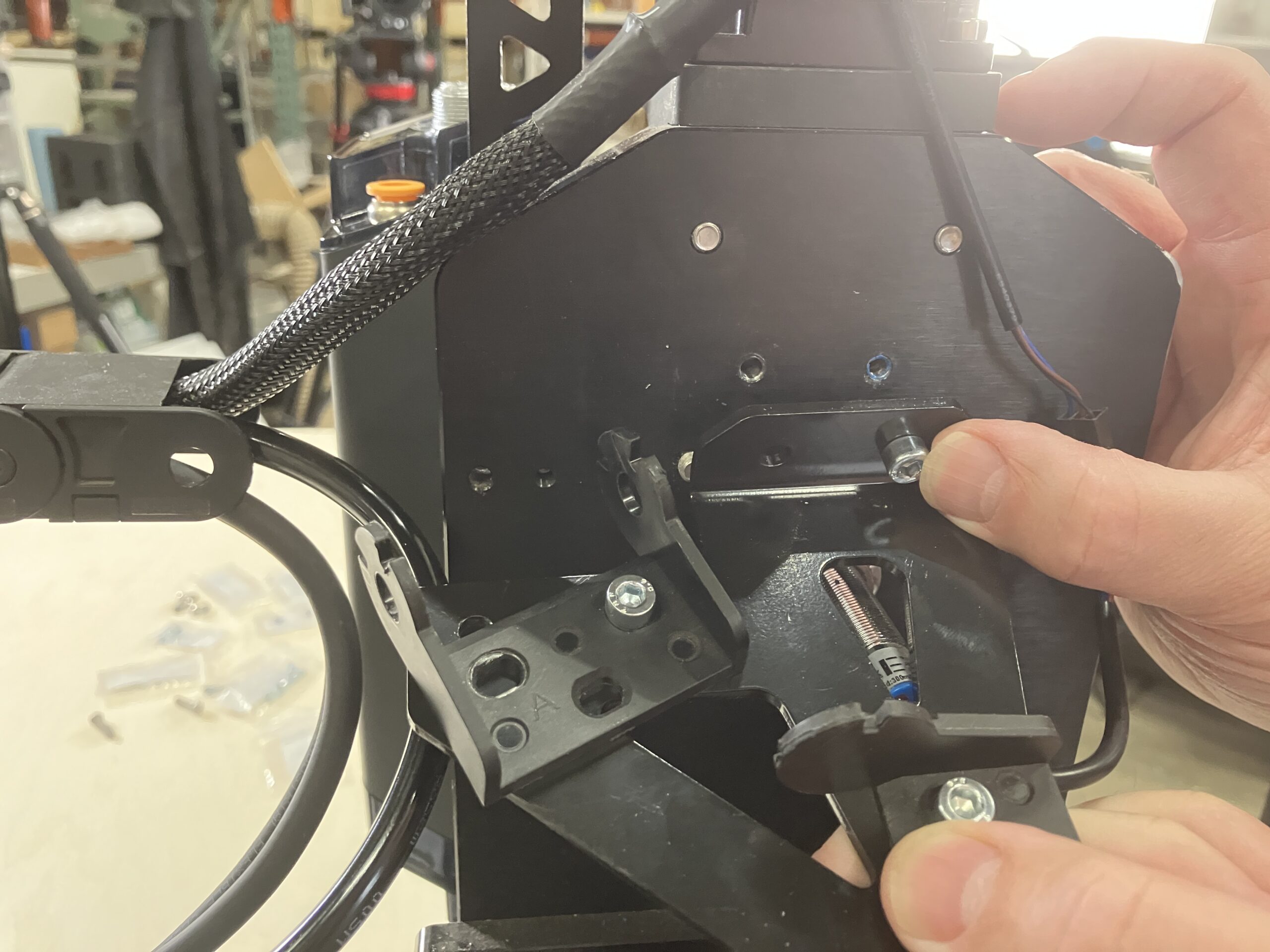
Remove Links from X-axis Drag Chain
-
4×4 users may need to remove 2 links from your X-axis drag chain. This gives you a bit more length for your spindle cable to reach your VFD.
Cable and Tubing Routing
Prepare the Cables
Gather the following from the ATC box:
- Signal cable
- Pneumatic tubing (10 m)
- ATC spindle cable (blue connector) – if it’s already installed on your AltMill, that’s great!
Place the cable ends and tubing near the spindle connections on the Z-axis.
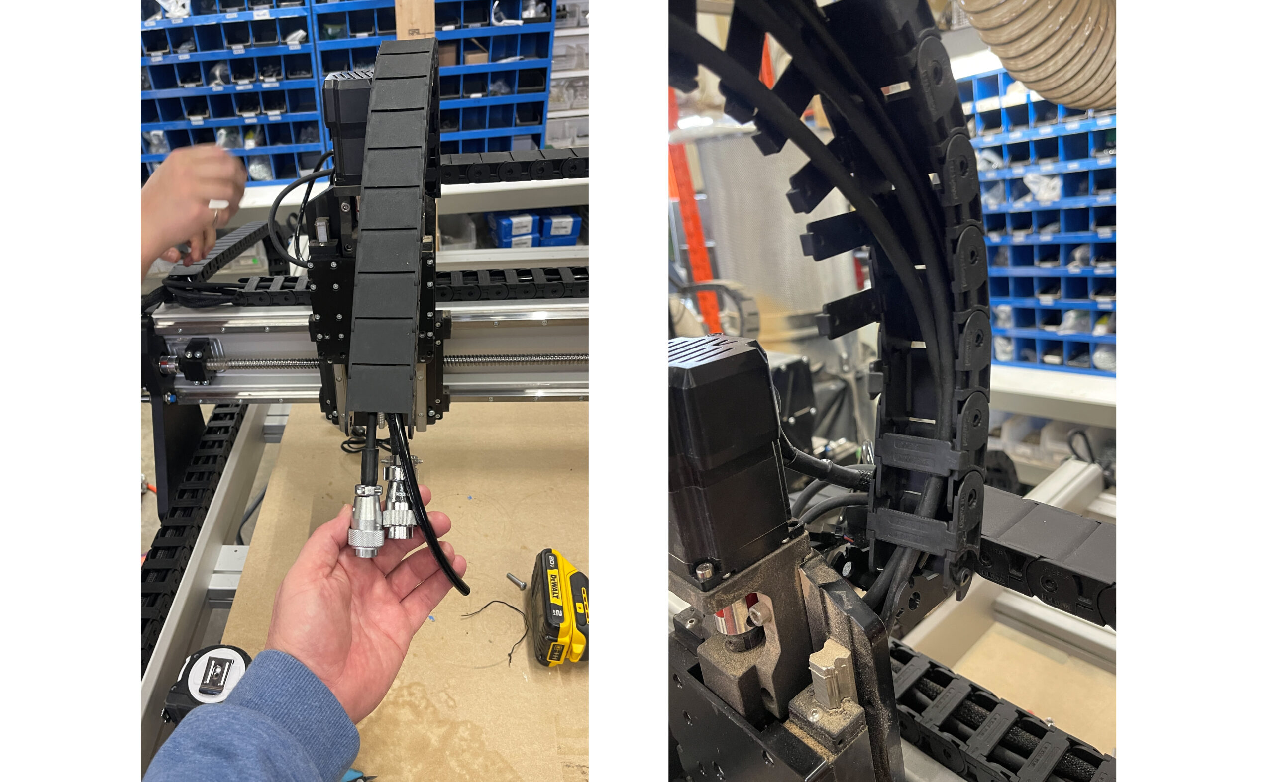
Route Through the Z-Axis Drag Chain
- Route the wires and tubing through the opening in the Z-plus drag chain bracket. If it’s tight, loosen the bracket slightly to widen the opening.
- Use a flathead screwdriver to detach the remaining clips on the Z-axis drag chain.
- Clip the Z-axis drag chain back onto its end links.
- Close the clips around the three cables.
- Use one M5 – 10mm screw and M5 lock nut to fasten the loose end link at the Z-plus drag chain bracket, from the previous section.
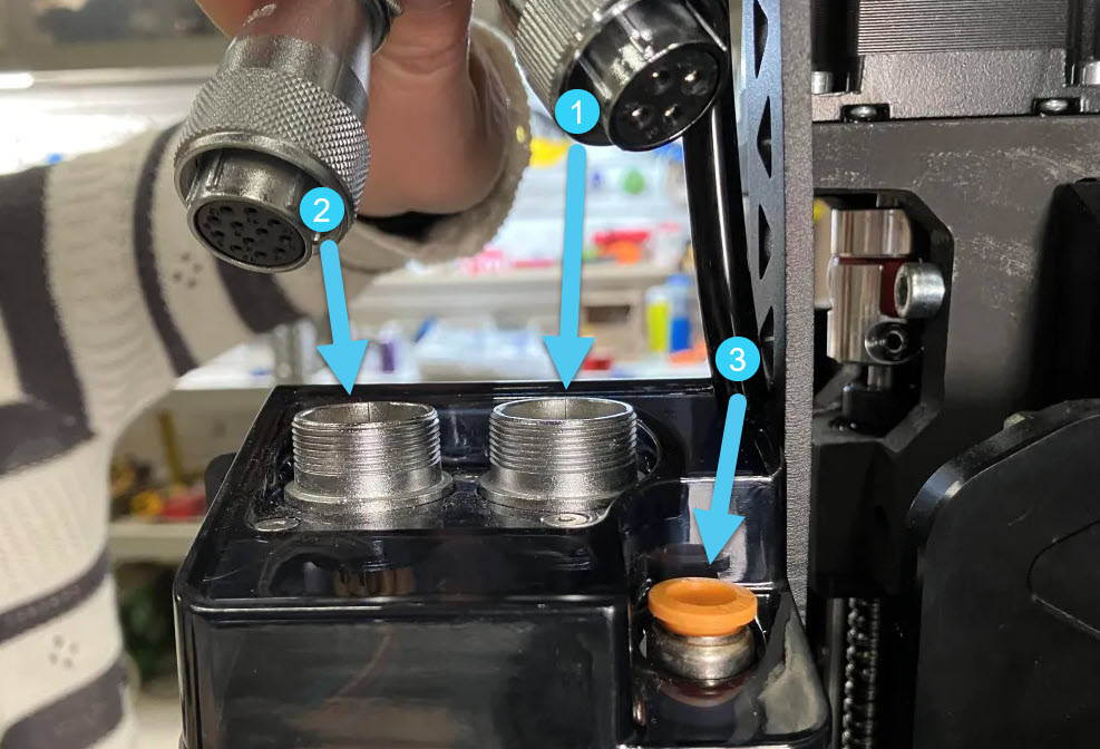
⚠️ Important: Keep cables and tubing parallel inside the drag chain & do not cross themConnect the Spindle
On the ATC spindle, connect the following in this order:
-
Spindle cable
-
Signal cable
-
Pneumatic tubing
⚠️ Ensure connectors align with the grooves on the aviation plug; misalignment may damage pins.
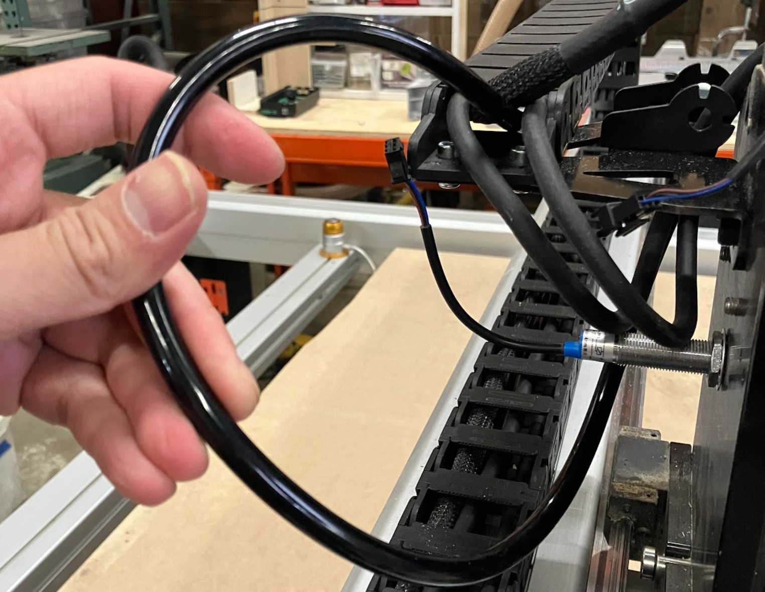
Route Through X and Y Drag Chains
-
Detach the X-axis drag chain from the end link on the XZ carriage. Open the clips, place the new cables and tubing inside, and close a few clips to hold them in place.
-
Run the tubing under the Z-plus drag chain bracket, before entering the X-axis drag chain. Leave some tubing out for strain relief.
-
Run the spindle and signal cables straight from the Z-axis drag chain into the X-axis drag chain
-
Make sure these do not cross or twist.
-
-
Adjust the cables and tubing as needed, then close the remaining clips along the X-axis drag chain.
-
Reconnect the X-axis drag chain to the Z-plus drag chain bracket.
-
Verify the spindle cable reaches the VFD through the table leg cutout.
-
Verify the signal cable reaches the SLB-EXT.
-
Ensure the tubing is free of kinks and sharp bends.
-
Finally, route cables and tubing for the Y-axis drag chain, adjust as needed, then close the clips.
4×4 Users
Congrats! You’ve completed the spindle setup steps.