
For this software setup, if you have a 4×8 AltMill you may want to grab a friend to help you with checking sensor position and lights on the ATC. Otherwise, be prepared to do some walking back and forth!
gControl Panel
At this time you can reinstall your gControl panel and mount, see mounting instructions here.
Power Up
- Plug the VFD power cable into an outlet and turn on the power switch at the bottom of the VFD.
- Turn on the SLB-EXT using its toggle switch, cycling the E-stop as usual.
Initial Hardware Checks
-
Verify the rack sensor is on, if you have it. It should be on if the rack has been installed correctly. There should be a red light coming from the rack sensor.
-
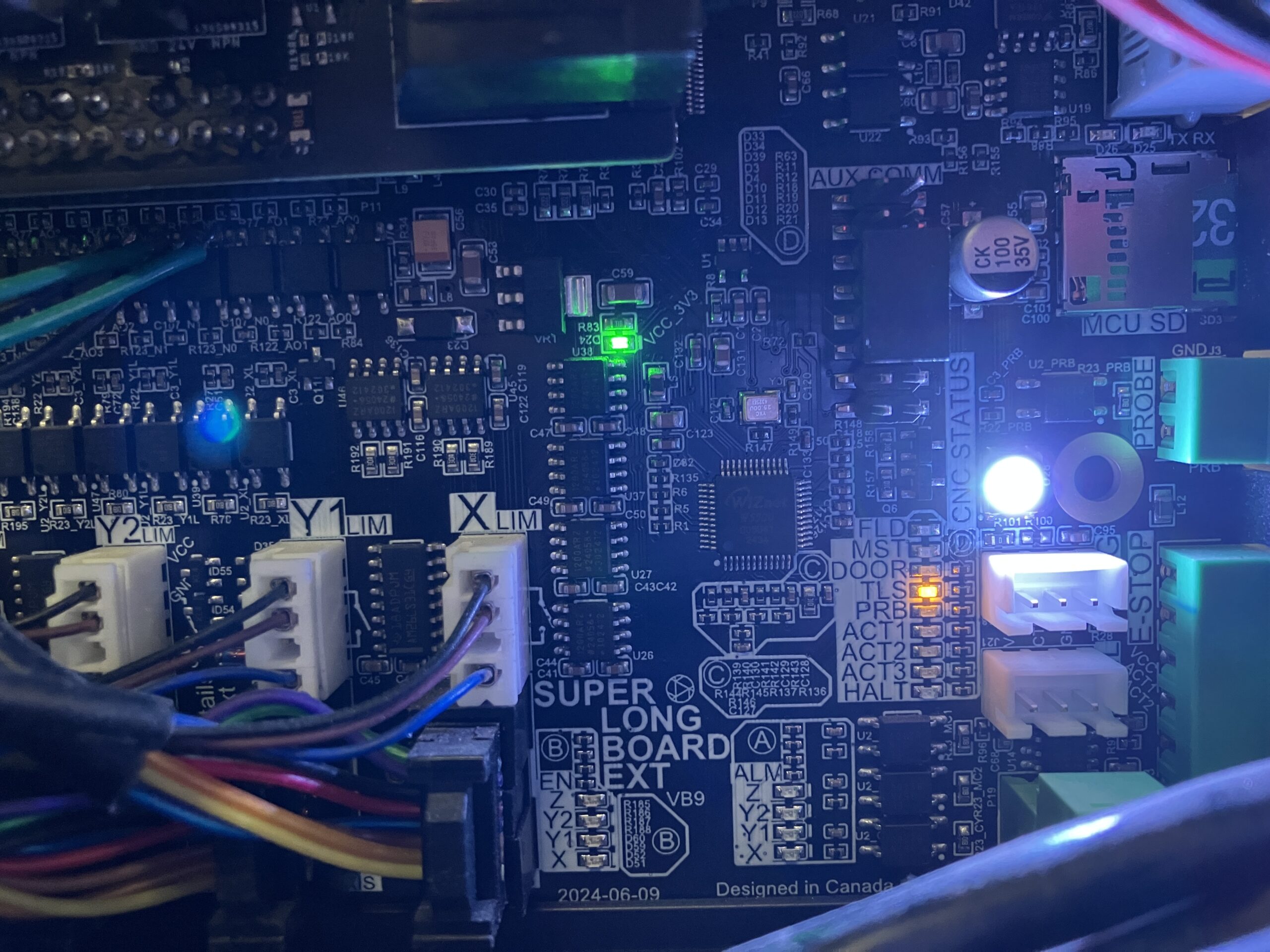
Check that the tool length sensor (TLS) is functioning.
- Press down on the TLS (either manually or by jogging the spindle down slowly), and confirm the orange TLS LED on the SLB-EXT turns off.
-
Check the white Pressure LED on the spindle is on.
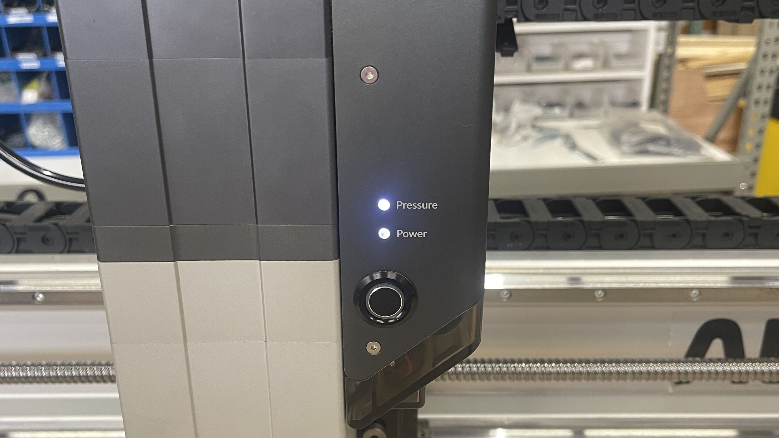
-
If the light is red:
- Check the air compressor gauge
- Check the filter regulator gauge
- Ensure the quick-disconnect ball valve is open
⚠️ The first time you connect to gSender with the spindle connected, air will leak because the system has not yet been configured.
gSender Setup
-
Open gSender and connect to your machine.
-
Check your controller firmware by clicking on the machine information icon, and verifying version 20260525 is installed.
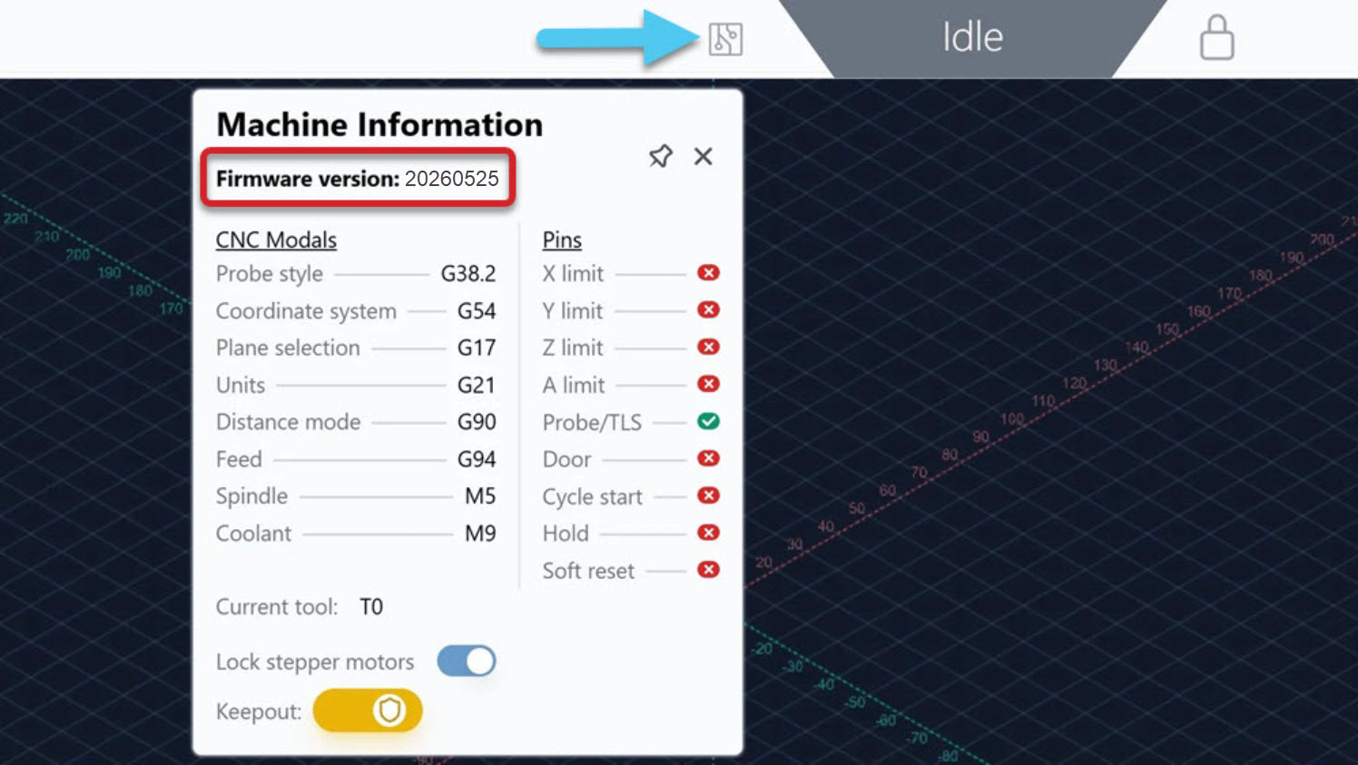
If not, please update by following the instructions here. Then come back to this page for the next step.
-
Once firmware has been updated, connect back to gSender and go to Tools.
-
If you haven’t yet, insert the microSD card into the slot on the SLB-EXT.
-
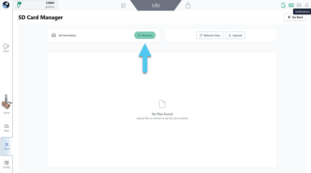
Go to SD Card Manager.
-
Ensure that gSender recognizes the card and shows it as Mounted
- We strongly recommend using the microSD card provided with your kit.
- Other SD cards may need to be reformatted to FAT32 and must not exceed a capacity of 32 GB.
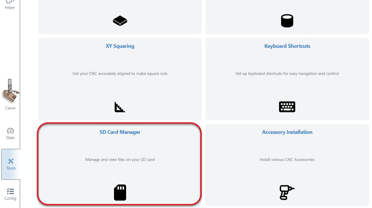
Accessory Installation
We will be using gSender to upload ATC-related g-code programs to the microSD Card.
-
Navigate back to the Tools tab, and click on Accessory Installation.
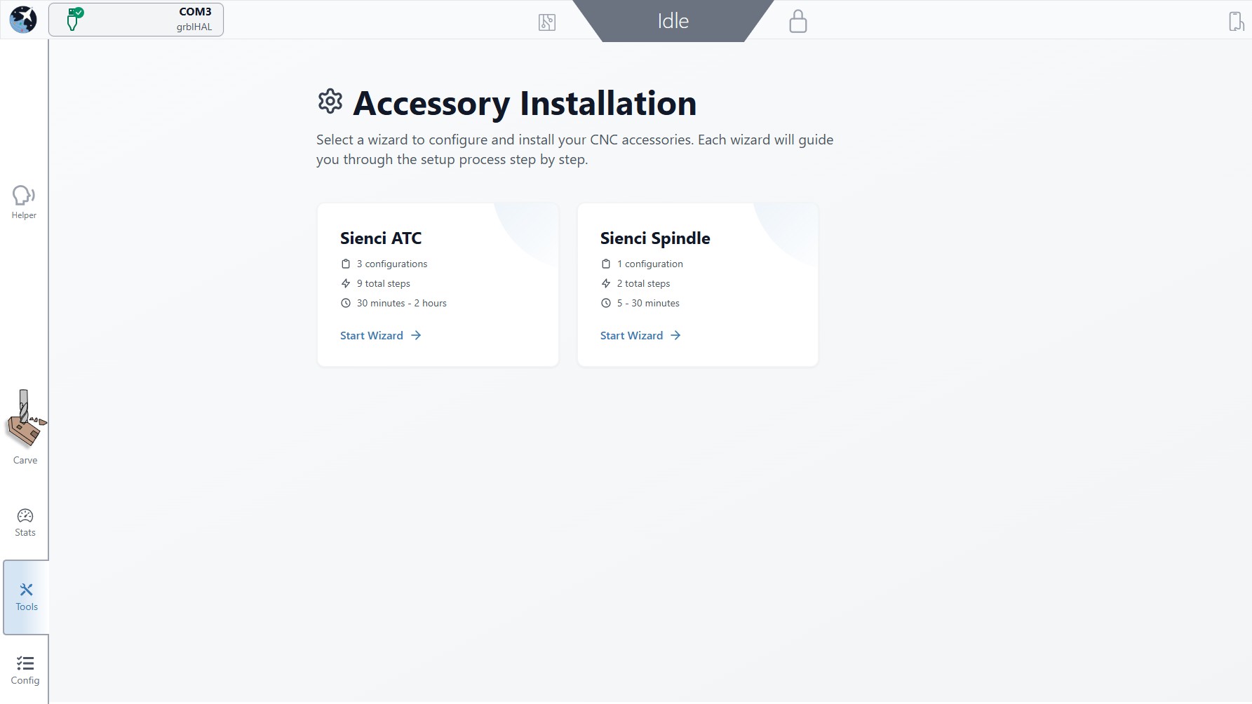
-
Select Sienci ATC to start the setup. This process should take approx 30 min.
-
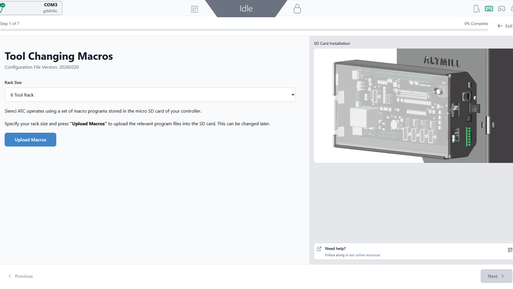
Select Initial Setup.
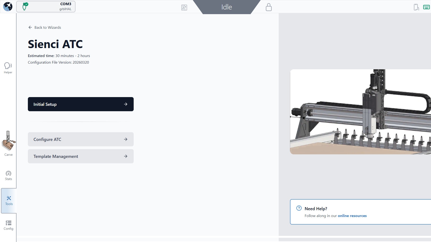
-
Select your Rack Size. For this example, we are selecting a 6 Tool Rack. Hit Upload Macros.
-
Once complete, press Next in the bottom right corner.
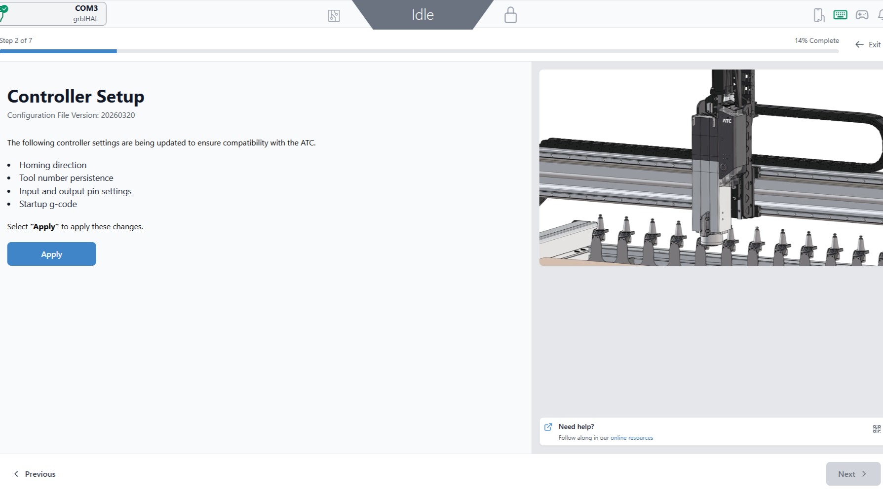
Controller Setup
-
This step will configure your controller. Hit the blue Apply button.
-
Once completed, hit Next.
-
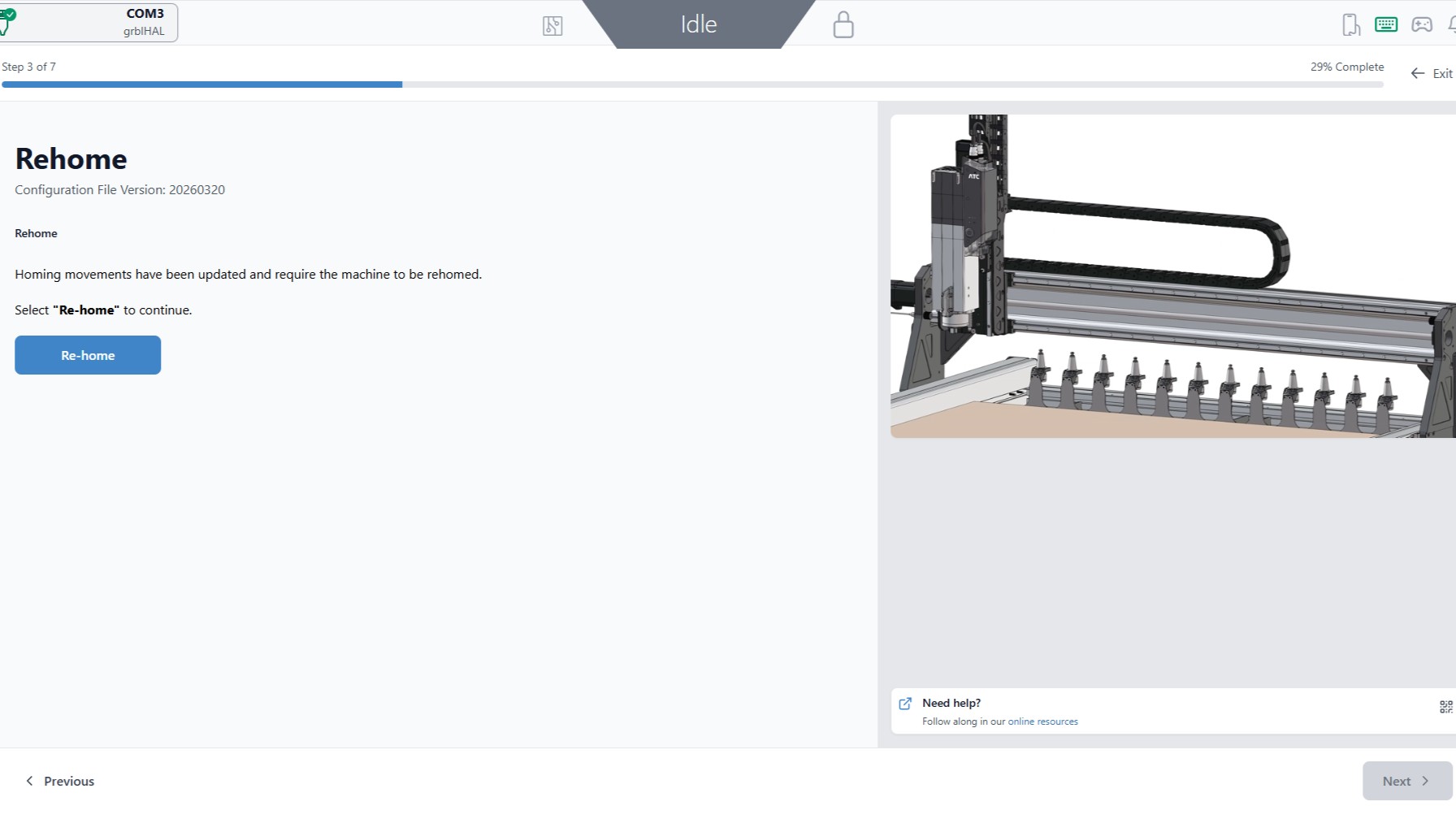
Next, the machine will update its homing position. Hit the blue Re-home button to begin this wizard.
-
Once the button turns green and shows Complete, continue with the Next button. At this stage, the air leak at the spindle should stop.
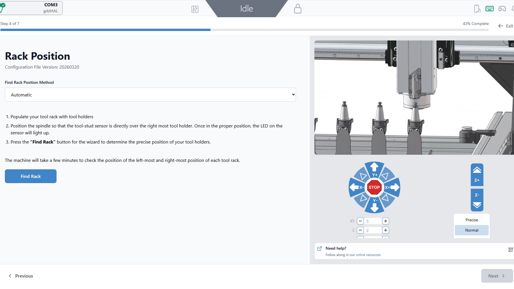
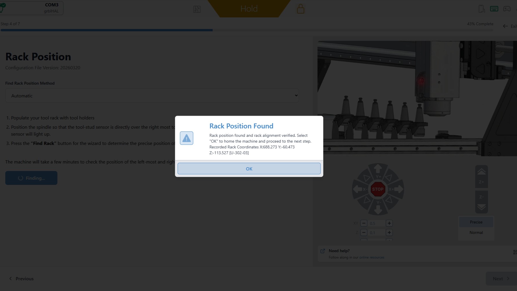
Rack Position
Next the rack location will be determined. You will be prompted to manually jog the ATC.
-
Ensure Automatic is selected in the drop down menu.
⚠️ Caution: Move slowly. Avoid crashing the stud finder or spindle nose.
-
Assuming you start from the back left corner of the machine, you will be moving the spindle above the right-most tool holder.
Manually jog to the right, to the front and then down. You will be moving approximately:
- 1140 mm to the right
- 20 mm to the front
-
100 mm down
These values are approximate, you will need to adjust especially if using a MK1 or early MK2
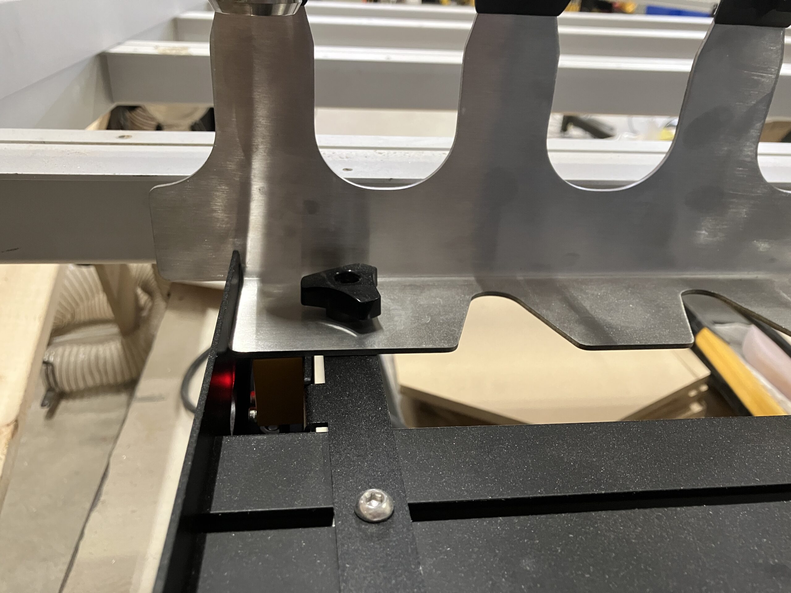
The goal is to line up the sensor on ATC over the tool holder stud, triggering an LED to light up. Aim for 1-2mm above the stud, and centered on the stud.
-
Use precise jog (short taps only) once you are close to the stud.
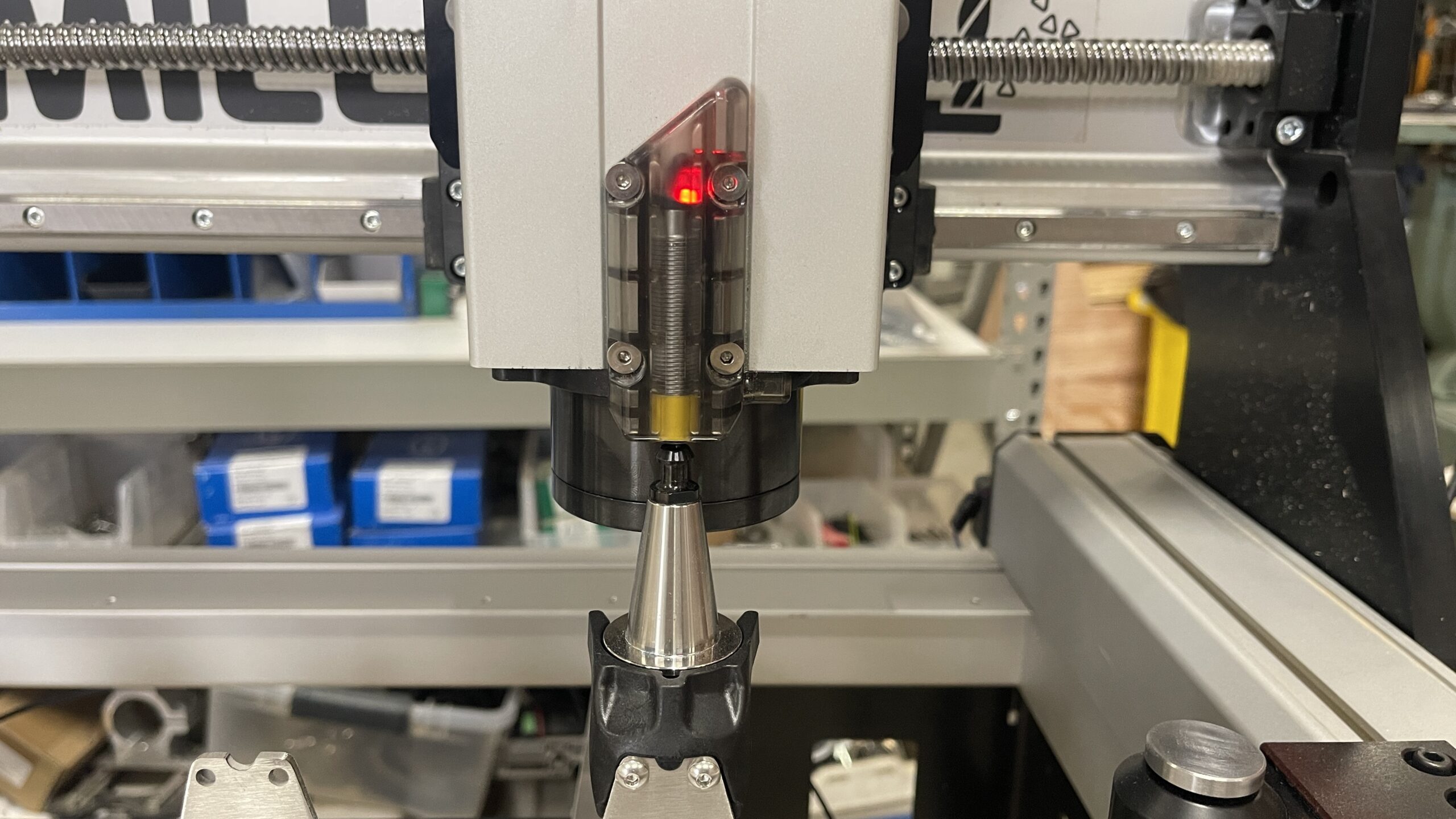
Once the light is on, hit the blue Find Rack button.
-
A Probing Sequence confirmation window will appear, hit OK to continue.
- The machine will move in a small grid pattern to re-locate the stud.
Once it successfully locates, you will see this confirmation window.
⚠️ If you encounter an error that it cannot find the stud, make sure to accurately position the sensor 1mm above the stud, centered on the stud. Just because the light turns red does not mean it is in the right position!
-
The locating process will now repeat for the left-most rack position. You will see another confirmation window pop up. Ensure the tool holder is mounted into the left-most rack position before continuing. Hit OK.
-
Once completed, if you have a 12-tool rack you will be prompted to repeat this process for the right and left-most positions on your second tool rack.
-
Click Next.
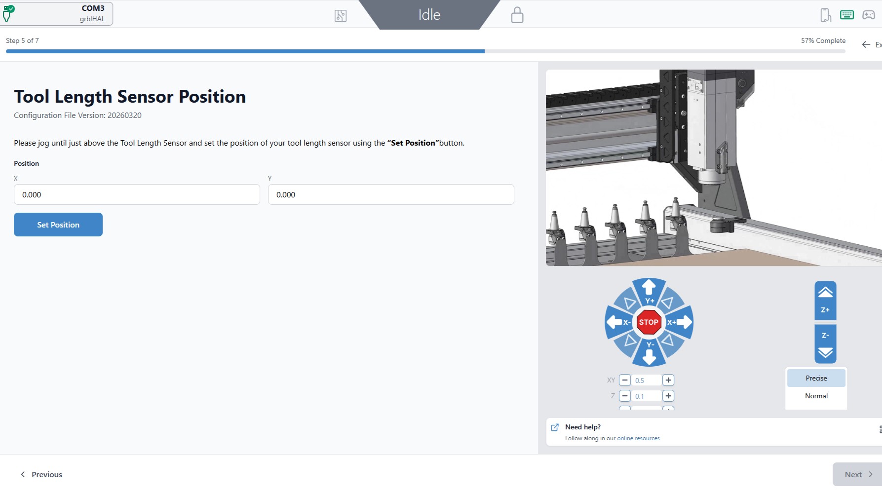
Tool Length Sensor Position
Now we will be setting the location of the TLS.
-
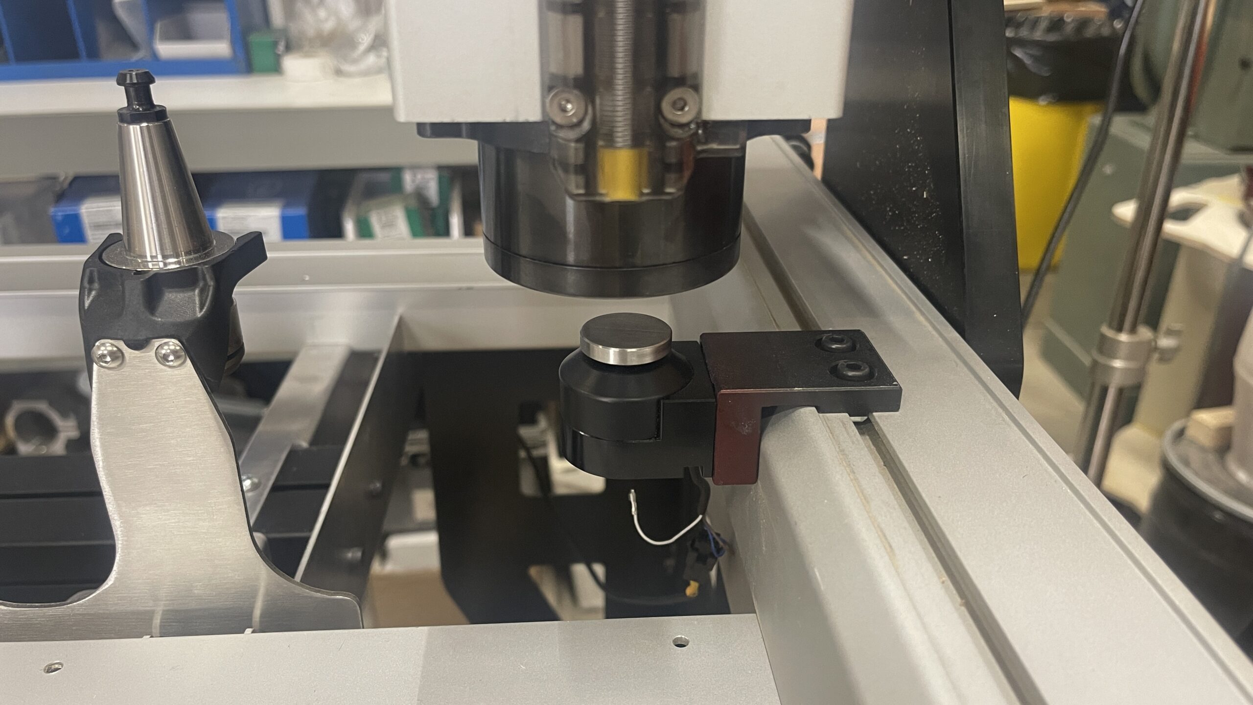
We are going to move the spindle all the way to the right side again, to set the location of the TLS. Jog until the spindle nose is directly above and centered on the TLS.
-
Hit the blue Set Position button.
-
Once the button turns green, indicating the position has been set, hit Next.
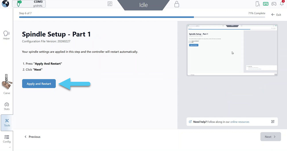
Spindle Configuration
In this section we will be power cycling and reconnecting to the SLB-EXT.
-
Hit the Apply and Restart blue button.
-
Hit the Next button in the bottom right corner.
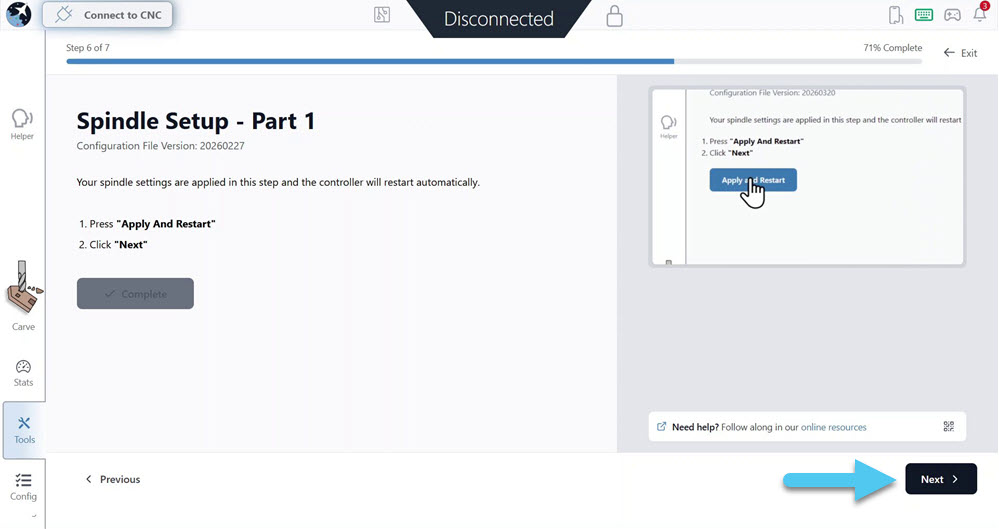
-
Reconnect to gSender.
-
Ignore the alarms, and hit the Apply and Restart button again.
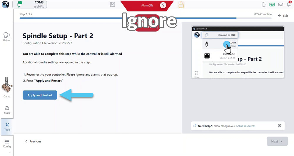
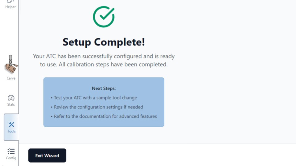
Once complete, click the Next button. Setup is complete! Exit the wizard now.
-
Go to Config -> Tool Changing.
-
Toggle the Enable ATC switch and hit the Apply Changes button.
Once complete, the following tabs should appear in gSender:
- Spindle / Laser – which will allow you to start up and run your spindle.
- ATC – which will allow you to change out tools.