
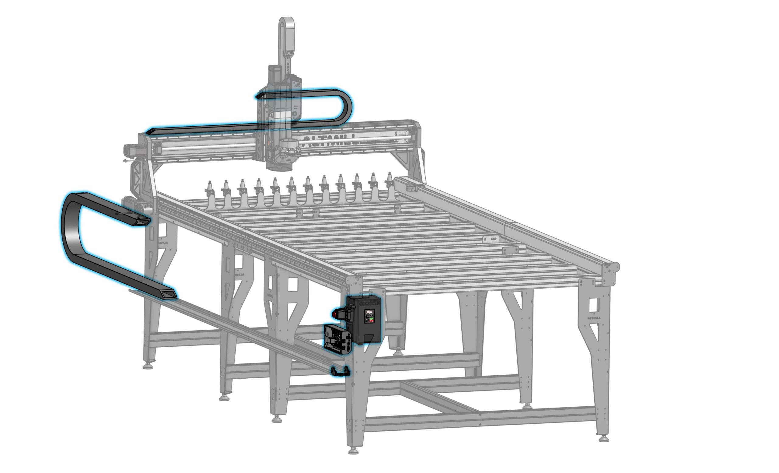
VFD Installation & Connections
-
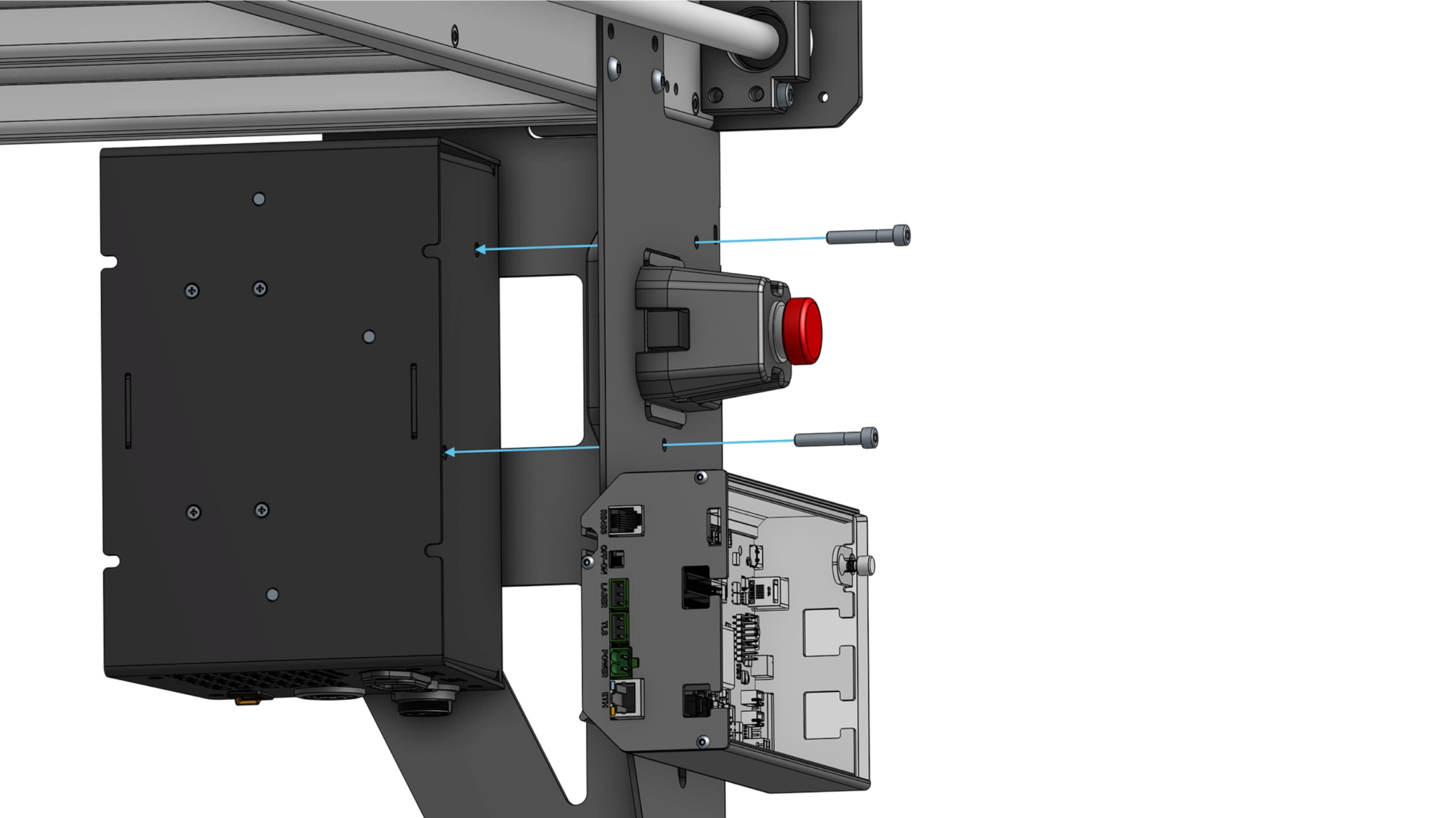
If you already have the VFD mounting spacer and E-stop assembled, go to the next step! Otherwise:
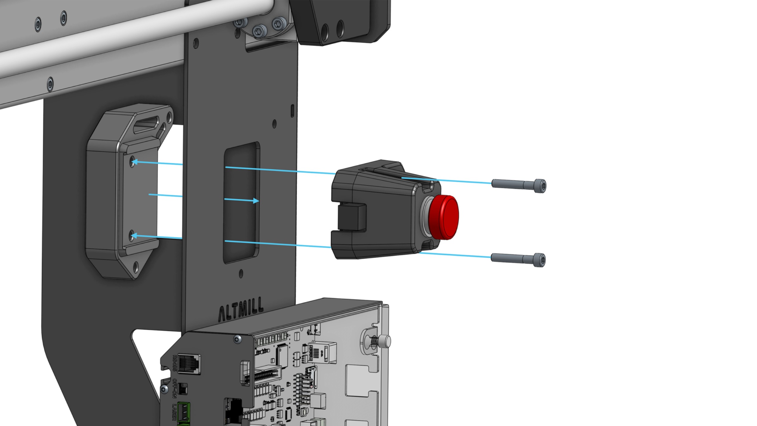
- Fully seat two (2) M5 lock nuts into the VFD mounting spacer. Place the VFD mounting spacer onto the inner face of the front-left AltMill leg, then assemble the E-stop on the outer face of the leg using two (2) M5-30mm screws.
-
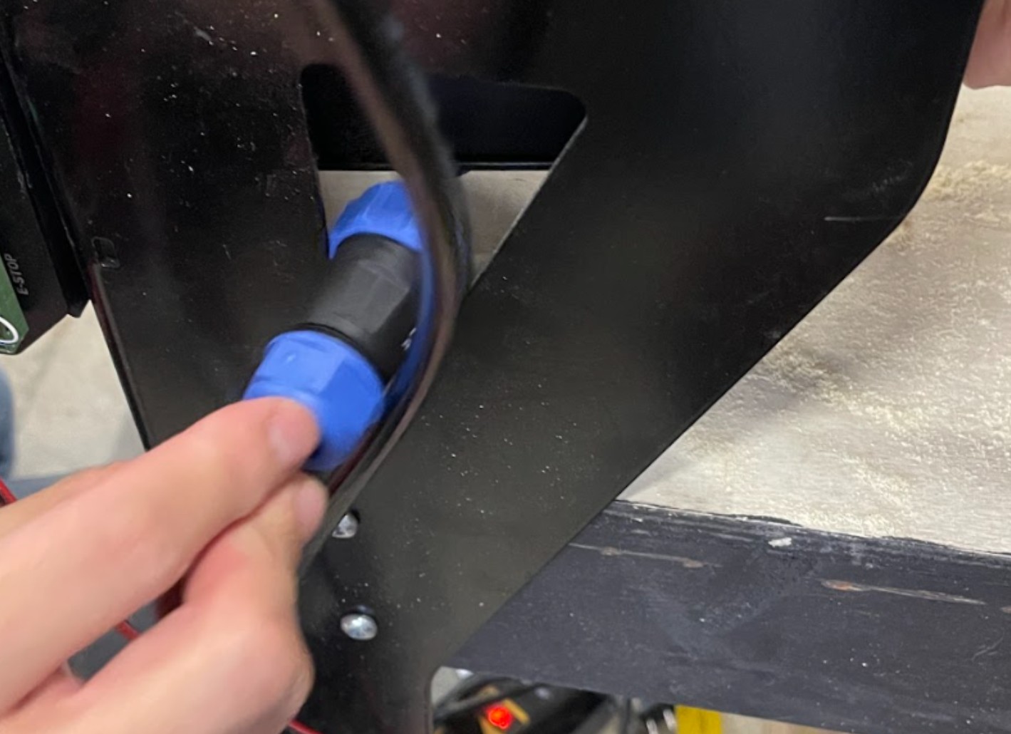
Route the blue connector from the spindle cable through the table leg cutout.
-
Plug the spindle cable connector into the bottom of the enclosed VFD.
-
Mount the enclosed VFD inside the table leg using the remaining two (2) M5 – 30mm screws. Ensure that the VFD is positioned so you can see the screen through the table leg cutout.
-
Plug the E-stop cable back into the SLB-EXT.
-
Plug the VFD power cord into the VFD.
-
Plug the coiled VFD controller cable into the VFD.
Finishing Up Connections
-
Turn off the SLB-EXT.
-
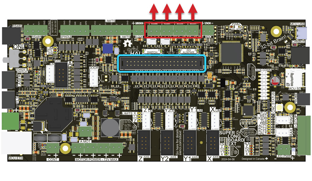
On the SLB-EXT, remove the top row of green connectors (marked in red), above the rectangular black header connector (marked in blue). We need to make space to install the ATC shield, which will eventually plug into that black header connector.
-
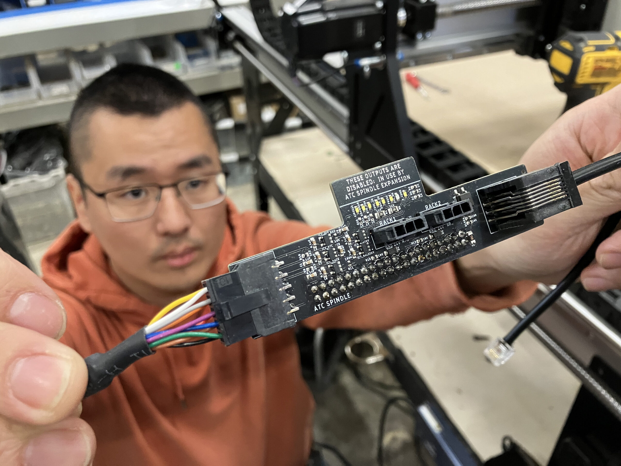
Connect the RJ12 cable into the ATC shield.
-
Connect the other end of the signal cable to the ATC shield.
-
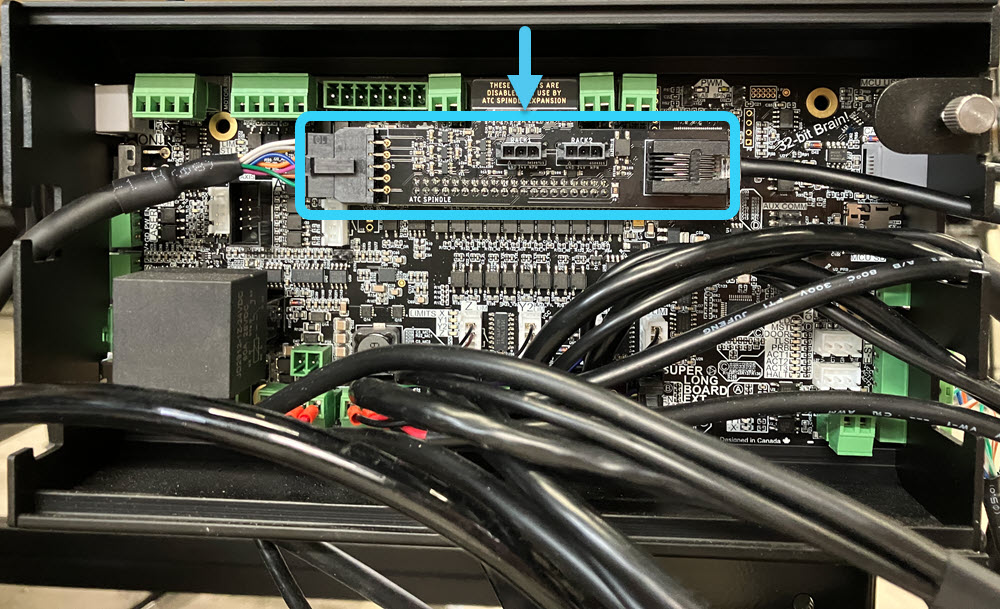
Then plug in the ATC shield onto the black header connector on the SLB-EXT.
-
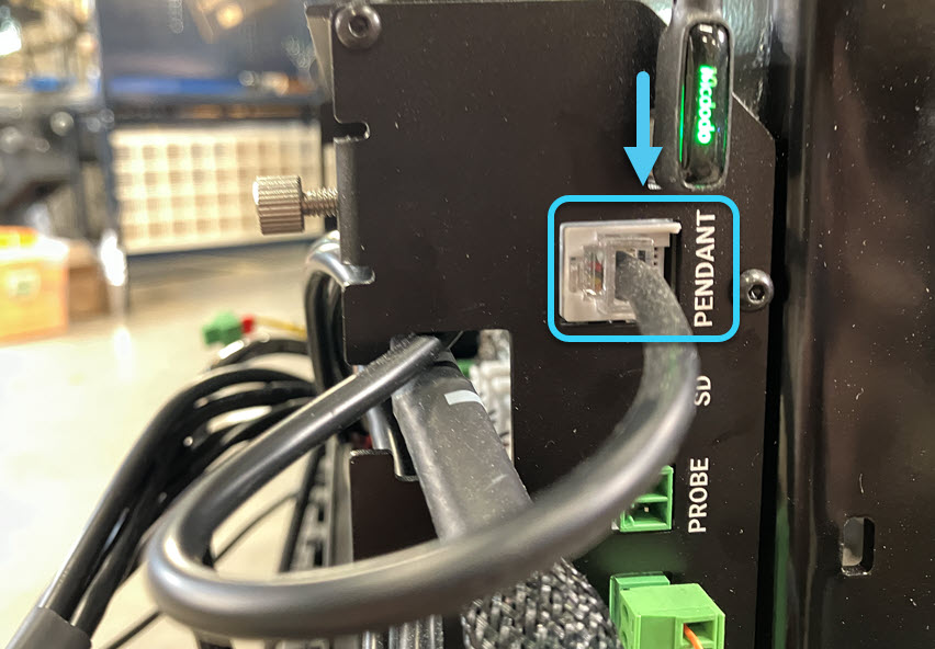
Connect the other end of the RJ12 cable to the PENDANT port on the SLB-EXT.
-
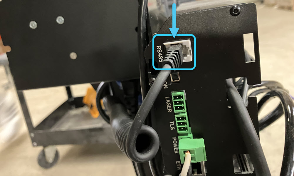
Connect the other end of the coiled VFD controller cable into the RS485 port on the SLB-EXT.
-
Insert the SD card into the SD card slot on the SLB-EXT. Make sure it fully sits in the port.
Wiring Sanity Check
Use this section to double-check all connections:
-
Spindle Cable
Spindle (aviation) → VFD (aviation) -
Signal Cable
Spindle (aviation) → ATC shield -
VFD Controller Cable
VFD (RJ / Ethernet) → RS485 port on SLB-EXT -
VFD Power Cable
VFD (IEC) → Power outlet (NEMA 6-15P) -
RJ12 Cable
ATC shield → PENDANT port on SLB-EXT