
Follow these instructions if you’re assembling a Vortex rotary axis kit which utilizes an open loop motor with the included rotary switching module.
Now it’s time to wire up the Vortex and install the rotary axis switch.
The switching module used to control your Vortex can be thought of as ‘intercepting’ the connection from your controller to your two Y-axis motors.
This procedure will take about 15 minutes.
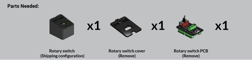
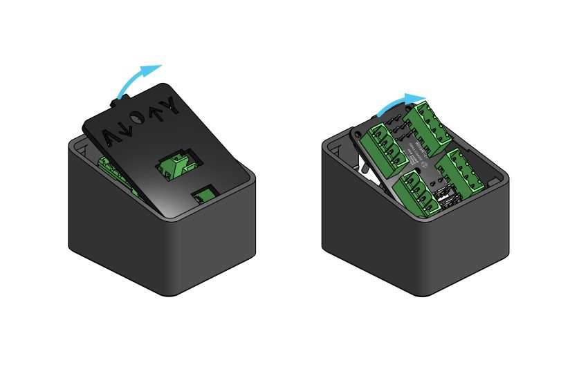
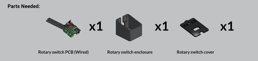
Begin by removing the cover and the PCB from the switch enclosure.
Please note that your switch may come with a different shipping configuration than what is illustrated above. Your toggle switch may also come with a small black protective plastic cap which can be unscrewed to remove for usage.
The key to this step is to separate the cover and PCB from the enclosure. You will also want to remove and discard the small plastic cap protecting the toggle switch if one is present.

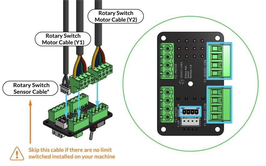
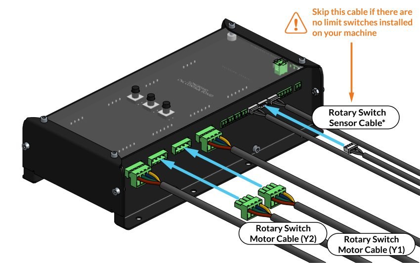
Now plug the 2 included rotary switch motor cables Y1 and Y2 into the connectors on the right side of the PCB.
*Insert the rotary switch sensor cable into the smaller white connector closer to the middle of the PCB if you have limit switches installed.
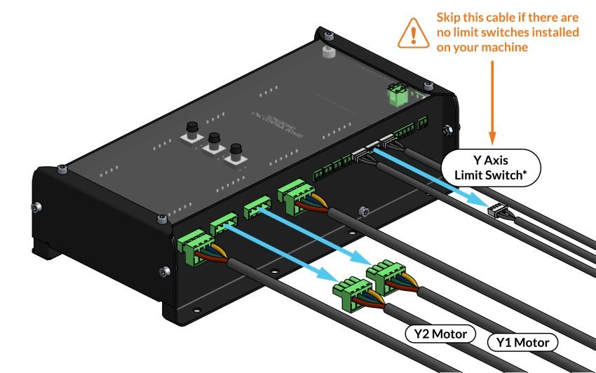
On your LongBoard, locate and unplug both Y1 motor and Y2 motor cables, and the Y axis limit switch (Ylim) cable.
*If you don’t have limit switches installed on your machine, there’s no limit switch cable for you to relocate.
Plug both Y1 and Y2 rotary switch motor cables into the LongBoard.
*Plug the rotary switch sensor cable back into the connection labeled Ylim if you have limit switches installed.
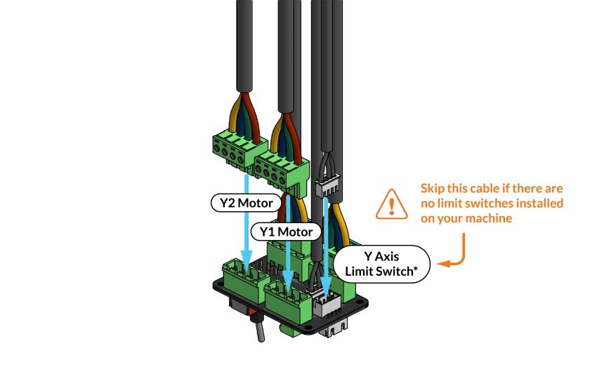
Plug both Y1 motor and Y2 motor cables into the left side of the PCB.
*Plug the Y axis limit switch cable into the smaller white connector closest to the edge of the PCB if you have limit switches installed.
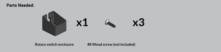
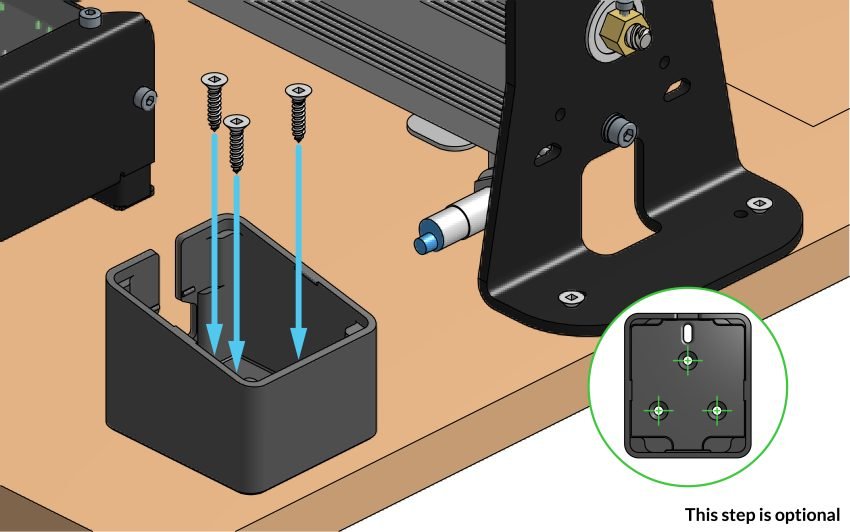
As an optional step, you can mount your router switch to your bench by screwing three #8 wood screws through the holes in the bottom of the enclosure.
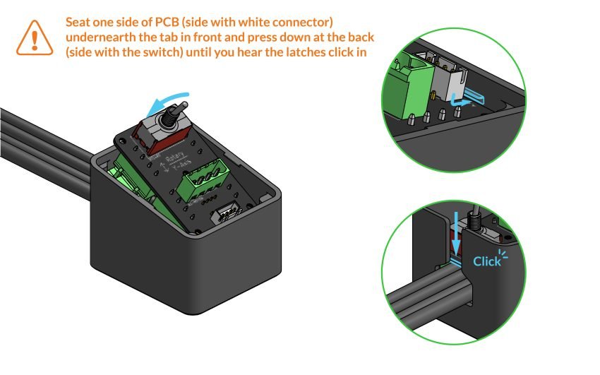
Place the PCB back into the enclosure with the switch facing the top and cables sticking out the back . Seat the PCB under the tab and press down on the switch until you hear a click.
Check that the green connectors do not come loose as you are installing the PCB.
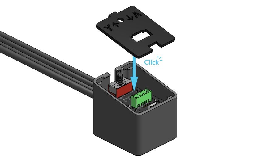
Place the cover on the enclosure with the tab matching the direction of the cables. Ensure it snaps in place under the tabs on each side.
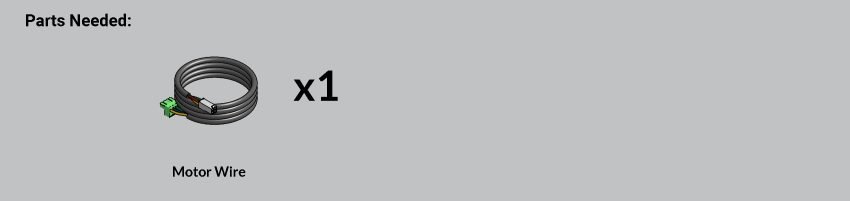
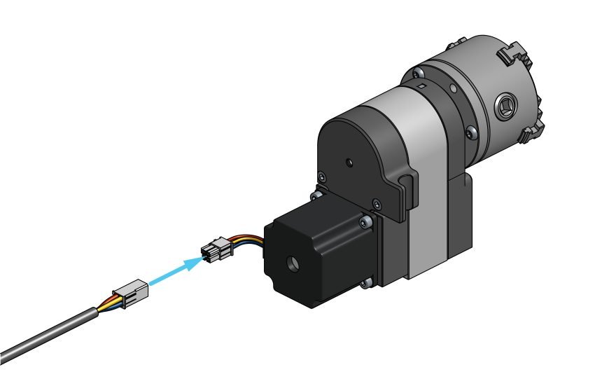
Grab the single remaining cable and connect the side with the white square connector to the white connector on the headstock motor.
Connecting Your Vortex
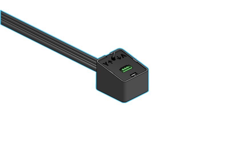
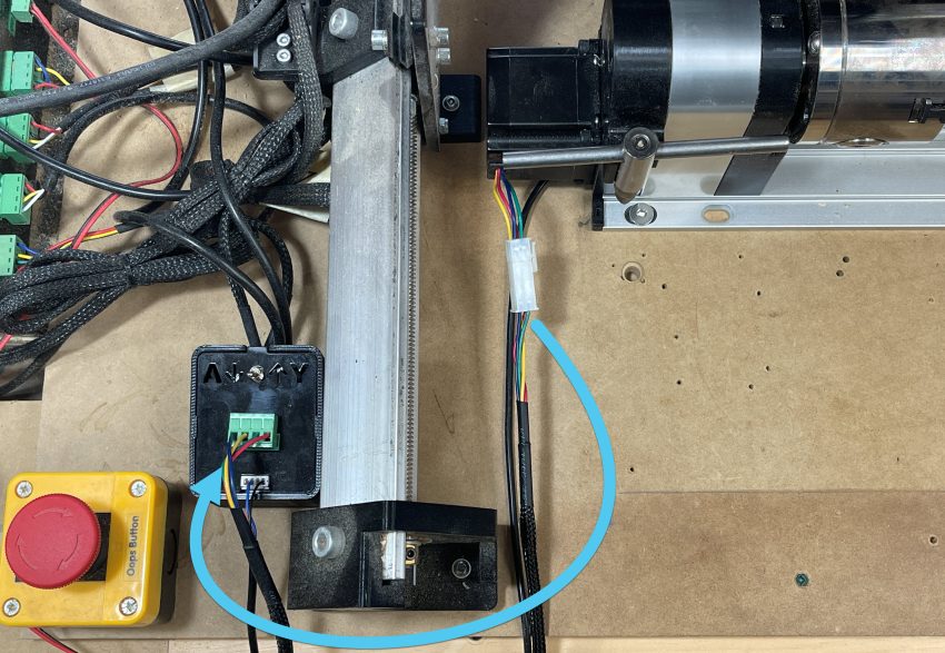
On the top of the switching module, you’ll find a single green plug where your Vortex motor cable will plug into. Run the cable(s) around your feet, not under the rails.
The inductive sensor cable coming from the Vortex can then be plugged into the single white connector on the top of the switching module if you are using the sensors.
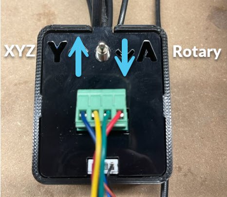
The Vortex rotary axis switch was designed to be left plugged in at all times, and allow you to easily enter Rotary Mode.
Pull the switch towards yourself for the A-axis (Vortex mode), or push it away from you for the Y-axis (Regular mode).
Congratulations! A job well done, you’ve completed the assembly steps. Take a deep breath, we are almost ready for a test drive.