
Rotary carving can be daunting, so we’ll need to learn to walk before we can run. Setting up your first project includes the same stages as a regular CNC project. Starting with a design, turning that design into a cutting program (a.k.a. g-code), and then running that program on your machine with your prepared material.
We will cover several key concepts in this project, including:
- Prepping Your Materials
- Generating g-code
- Workholding
- Axis Alignment
To complete this project, we will be using:
- A 3” section of round or square wood with a diameter of 1”
- VCarve Software
- ¼” tapered ball end mill
- gSender
- LongMill with Vortex attachment
- Chess Queen .STL file
- Queen chess piece .g-code file
Follow along this simple and fun project where we’ll make a chess piece. It should be noted that this project won’t cover every topic related to rotary carving, but is focused on the basics to get you a solid base of understanding how to run a job on your rotary.
This First Project is small and will carve slower than you may expect, which is deliberate. We want to walk before we run. This project should take about an hour to carve, but our current Edge build doesn’t report runtime very accurately. Once the project carve is underway, feel free to increase the speed manually, with the feed override in gSender.
Once you are able to tackle this simple chess piece, we will introduce a couple more advanced techniques like adding tabs, using the tailstock, adjusting feeds and speeds, and more in a second intermediate project. Let’s dive in!
Prepping Material
You can use the Vortex to machine all of the materials you are already using on your LongMill. Softwood, hardwood, plastic, acrylic and more! Softer woods such as pine are recommended for this project in order to be a bit more forgiving of mistakes, easily available, and cheap.
One of the trickier parts of a rotary axis project can be finding stock for your project that is suitable. Thankfully, there are a few options for getting or making your stock.
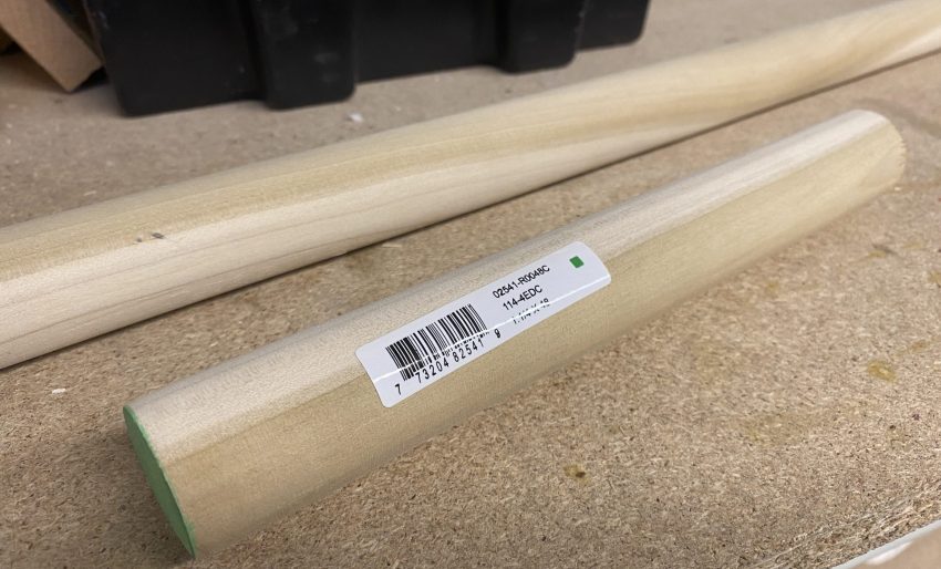
Round Stock
- Depending on which sources you have in your area, you may be able to find round blanks used for woodturning on a lathe. These will typically be a more expensive option, but can be very convenient.
- Large diameter dowels from your local hardware store are also suitable, however these typically aren’t sold in diameters of much larger than an inch.
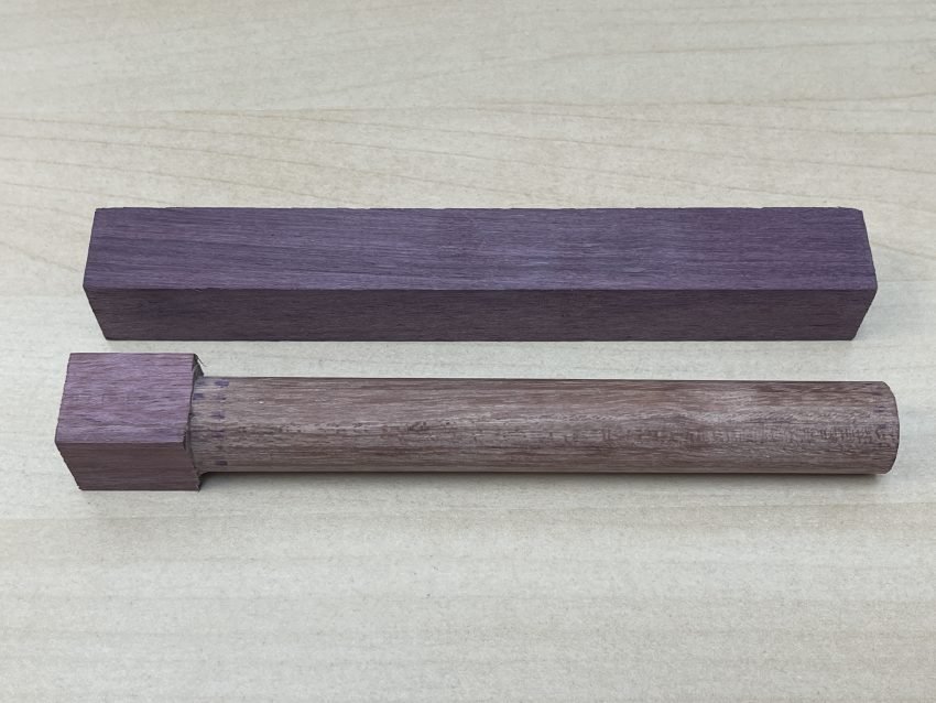
Square Stock & Surfacing
- The Vortex can easily make round, cylindrical objects, so thankfully we can use this to turn square or rectangular stock into round stock as well – a perfect starting point for our project.
- This is also useful for irregularly shaped wood such as unprocessed wood or even entire untouched logs or branches.
- Use gSender’s built in ‘Stock Turning’ tool to turn stock down into cylinders.
Whichever method you go with, keep in mind that you’ll need to size your stock to be 4” or less in diameter, and 21.5” or less in length. If you have a 48×30 LongMill and you’re using the optional extension track, your stock can be up to 39.5” length.
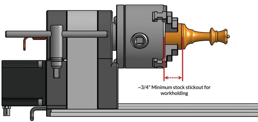
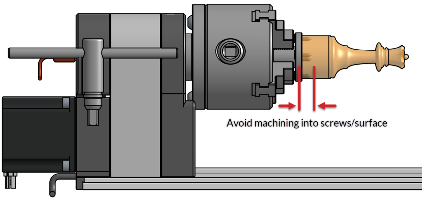
You’ll usually want to leave a bit of extra length of unused stock material where the material will be held, so make sure to account for this before cutting your material. If you’re holding the material with the jaws of your chuck, you’ll need to leave ~¾” minimum of extra stock sticking out. If using the workholding faceplate option, which is screwed onto your stock, you can opt to leave no extra stock. Be mindful to avoid machining into any screws sitting below the surface of your stock.
Generating g-code
Generating the g-code for carving your chess piece project is quite simple and can be broken down into five steps:
- Configuring your rotary project-specific settings in the ‘Job Setup’ window.
- Importing and configuring a component/3D model.
- Generating toolpath(s)
- Post processing/exporting your project to g-code
As an example project, we’ll be carving out the queen. This is a simple model that can be made fairly quickly from small stock, or in an exaggerated scale with a large piece of stock. Don’t be afraid to get creative with whatever material you have on hand!
Job Setup
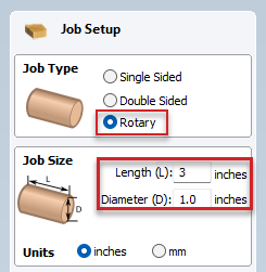
When you first create a new project in VCarve/Aspire, you’ll be greeted by a ‘Job Setup’ window prompting you to enter some details about your project type and size.
Since we’ll be working with a rotary project, we’ll of course select the ‘Rotary’ job type. We can now enter the length and diameter of the stock we plan on using. For our project, we’ll be using a 1” diameter wooden dowel. Since we’re going to scale our model to fit inside the 1” diameter of our stock, the height we’ll need for our stock will change, so we’ll leave this as a value of 3” for now.
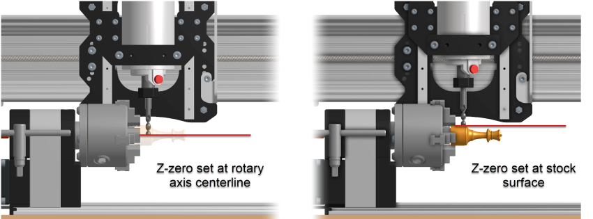
Next, you’ll need to select the Z zero position. This differs quite a bit from the traditional Z zero position set on the top of your material which you might be used to. Since we have a known, repeatable, rotating center axis, we typically prefer to use this as our origin position. This means that when we go to run this project, we’ll use the built in Z zeroing functionality in gSender to probe the Vortex’s chuck and set the Z zero position to the rotary axis centerline automatically.
Of course you can always use the cylinder surface as your Z zero position. Then manually set your zero at the surface of your stock in cases where you don’t know your stock diameter or are only engraving the very surface of the stock.
For a regular CNC project, the last two datum positions you’d need to set up would be your X and Y, usually done by selecting a corner or center position like shown below.
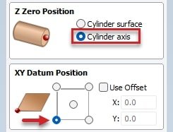
In our case the Y-axis datum will actually be our A-axis datum. So we will be going up and down on our Z-axis set to the center of our stock, and left and right with our X-axis. The Y-axis becomes our A-axis, turning the stock 360 degrees. In the case of the X-axis, it’s usually preferred to set the X-axis on the left side (chuck side) so that we can assure we won’t crash the bit into the steel chuck if our project size is set incorrectly.
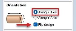
Lastly, you’ll find the option to choose whether your orientation is set up so that it spins along the X-axis or along the Y-axis, and the options to flip your design so it’s positioned along the rotating axis. In the case of the Vortex, our rotary axis spins parallel to our X-axis, so we’ll select Along X Axis, and ensure that Flip design is checked.
Importing 3D Model
With the project workspace now set up, we can import an existing 3D model to work from. For this example, we’ll import an existing STL model.
The model we’ll be working with is the ‘chess queen’ .STL file by Tim Edwards / CC BY-SA. If you’d like to follow along with the rest of the process as we bring this chess piece to life, scroll down to find the file ‘scad_chess_queen.stl’ from the list of downloadable models at this link and save this to your computer.
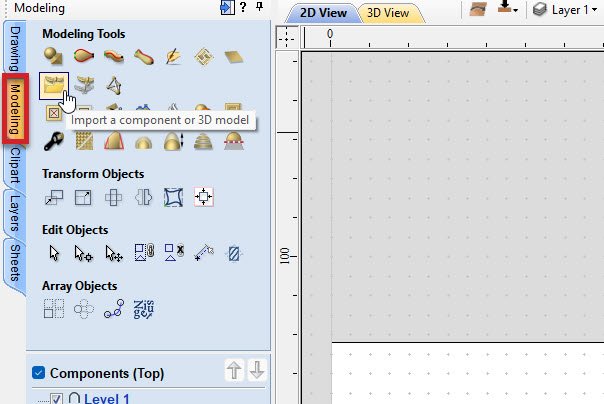
VCarve/Aspire is particularly good at handling imported 3D models for rotary axis work. Click on ‘Modeling’ then click ‘Import a component or 3D model’ to open the file browser. Here, you can choose the 3D model you’ll be working with, in our case – the ‘scad_chess_queen’ .STL file.
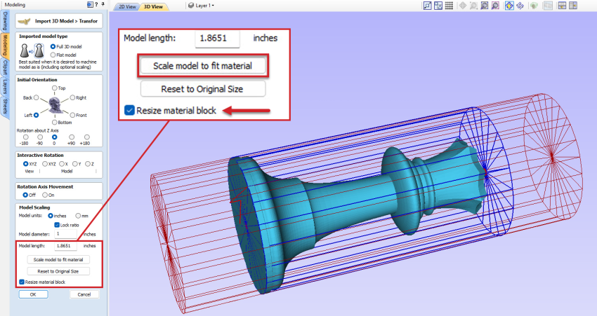
The imported model will be previewed showing its current orientation with the rotary axis, with stock size/orientation designated by the red wireframe cylinder. When this model is first imported, its scale/dimensions will be unchanged. Since we aren’t too concerned with the dimensions of this piece, we’ll scale this to fit our stock later on.
Since we know we’ll be using 1” diameter stock for this project, we’ll now scale our imported model so that its outside diameter is also 1” by typing this into the ‘Model diameter’ field in the ‘Model Scaling’ section. We’ll also select ‘Resize material block’ which will automatically resize the length of our stock to carve as the height of the imported model – in our case, 1.8651” long. This automatic material resizing is why we left our material length in the ‘job setup’ tab as 3” since we knew we’d resize this later on.
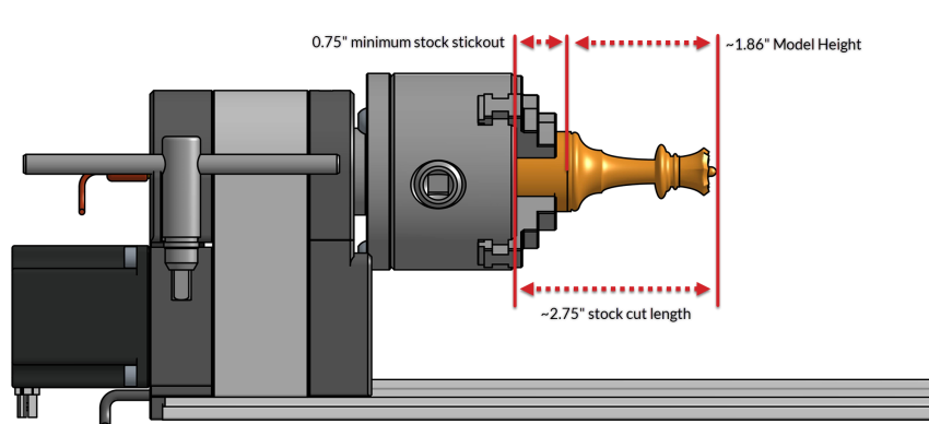
To fit this adjusted model height, we’ll cut our stock to be ~2.75” long which will leave us just over 3/4” of length to hold onto the bottom of our chess piece white we carve it. This extra stick out length also serves to ensure the cutting bit doesn’t end up crashing into the steel jaws of the chuck.
You’ll want to ensure that you’ve got at least 3/4” of extra material length held in the jaws. Leave a reasonable amount of clearance from your model’s starting point in the X-direction, to the chuck jaws.
If you leave a bit of extra space, you can even use the Vortex to cut off the finished chess piece!
Generating Toolpaths
Now that all your project geometry is settled, we can focus on generating the toolpaths for getting this project cut. This is the easy part, since generating toolpaths for a rotary setup follows the exact same process as generating them for a regular XYZ carving setup which you’ll likely already be familiar with.
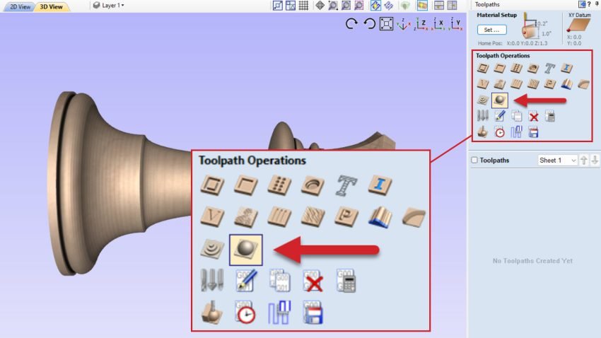
For 3D models such as the chess piece model we’ve imported, you can simply select a 3D roughing or 3D finishing toolpath, and VCarve/Aspire will handle generating the toolpath to carve out the entire 3D geometry. In our case, we’ll choose only a 3D finishing toolpath using a ¼” tapered ball end mill. With this simple chess piece model we can get away with using only a single toolpath, avoiding the need for tool changes. To learn more about tool changes, check out the Tool Changing section of Your Second Project!
‘Feeds and speeds’ or rather cutting parameters can be left unchanged from what you might normally use on a regular XYZ 3D carving. This First Project is small and will carve slower than you may expect, which is deliberate. We want to walk before we run. To jump ahead and learn more about rotary speeds & feeds, you can visit this page. You can import our Vectric tool database available here, to access a variety of cutting bits and their respective cutting parameters across several materials.
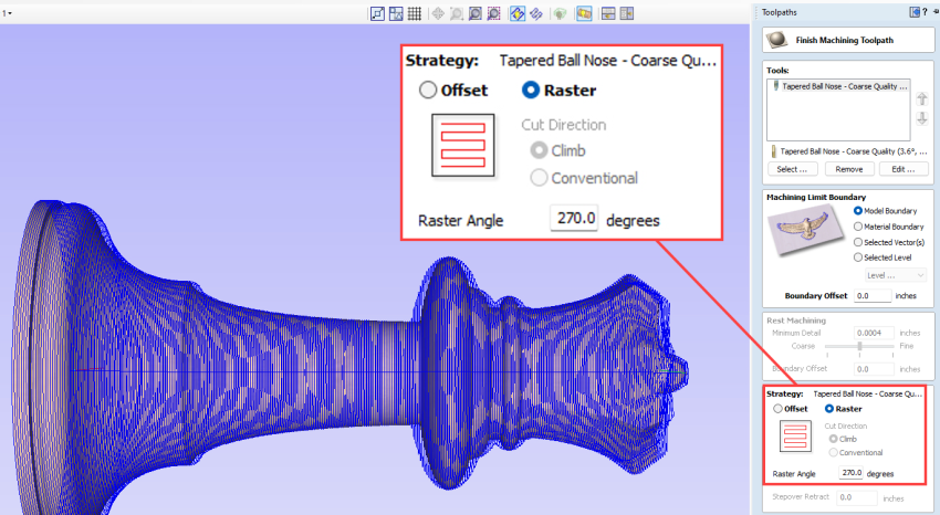
Just like with regular XYZ 3D carving, you’ll have the option of either creating an ‘Offset’ type tool path, or a ‘Raster’ toolpath. While either one will work, using a raster type toolpath will generally produce a cleaner carve and hide any toolpath marks a bit better.
‘Raster Angle’ will define whether the toolpaths will be generated with cutting passes moving along the X-axis or in the direction of rotation. Set this to 270 degrees in order to cut along the rotating axis, starting from the left side (with the stock rotating), or 0 degrees to cut along the X-axis (cutting passes going side to side).
0 degree raster angle (cutting in the X-direction)
270 degree raster angle (cutting in the A-direction)
For our example we’ll set this as 270 degrees so we’re cutting along the rotating axis. This will allow us to cut across the grain of our wood for a cleaner finish, while also looking much cooler as the toolpath progresses!
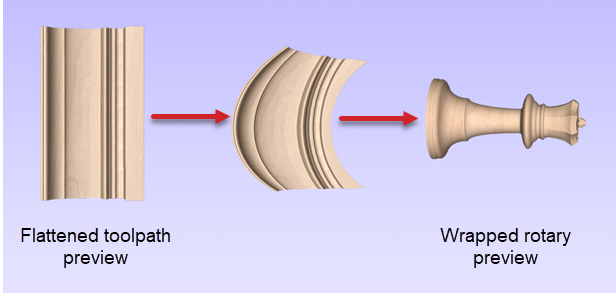
Once you’ve calculated/generated your toolpaths, you can preview these by clicking the ‘Preview Toolpaths’ icon, then clicking ‘Preview All Toolpaths’. This preview will first show you a simulation of all toolpaths carving out your project on a flat/unwrapped surface, and will then re-wrap this to show you the preview of what your carved model will look like. This is a great opportunity to see what VCarve/Aspire is actually doing behind the scenes. It’s ‘unwrapping’ the model around it’s center axis to be a flat model, generating the toolpaths for this flattened model, and then finally re-wrapping those same toolpaths and machined geometry around that same center axis.
Exporting g-code
Before we can export the g-code for our project, we’ll need to select the correct post processor specific for generating programs using A-axis commands instead of Y-axis commands. Check here for more information on installing the Vortex post processors.
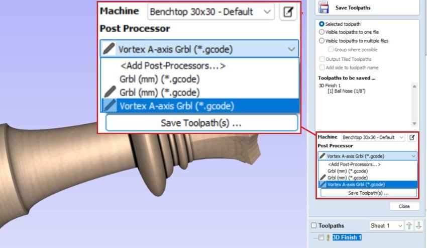
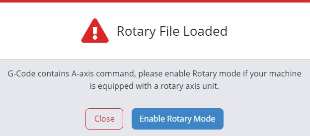
Queen Chess Piece g-code is a copy of the g-code file you will save. When this type of g-code file, generated using this post processor is opened in gSender, you’ll be notified that the file uses A-axis motion commands and reminded to enable ‘Rotary Mode’ for running the project.
Preflight Checklist
What we’ve done so far:
- Installed new Post Processors in VCarve
- Assembled and Mounted the Vortex
- Measured and Prepped your material
- Exported g-code
Before we take off:
- Secure our stock in the Headstock
- Align the Y axis
- Enter Rotary Mode
- Have the Correct Bit in place
- Set the X & Z axis
Workholding
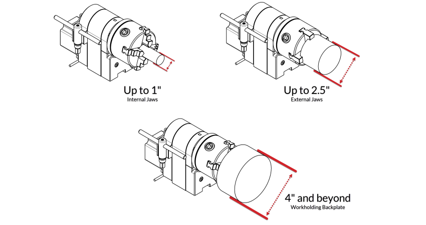
Depending on the diameter of your stock, you’ll need to use either the chuck’s jaws or the screw-on workholding face plate included with your Vortex. You can reference the maximum diameter capacity for each of the three workholding configurations shown below.
Because our stock diameter used for our chess piece project is 1”, we’ll swap in the internal clamping jaws shown in the first configuration below, and clamp the wood directly into the chuck.
The tailstock used on your Vortex is generally only required when cutting out a model that has a length 3 times its diameter. Since our model is 1” at its largest diameter, and less than 2” in length, we won’t require using the tailstock.
Y-axis Alignment
The last step to getting your Vortex fully ready to use is jogging your Y-axis towards the rotating center of your Vortex, and running an automatic touch probing sequence to align your Y-axis with your Vortex’s A-axis.
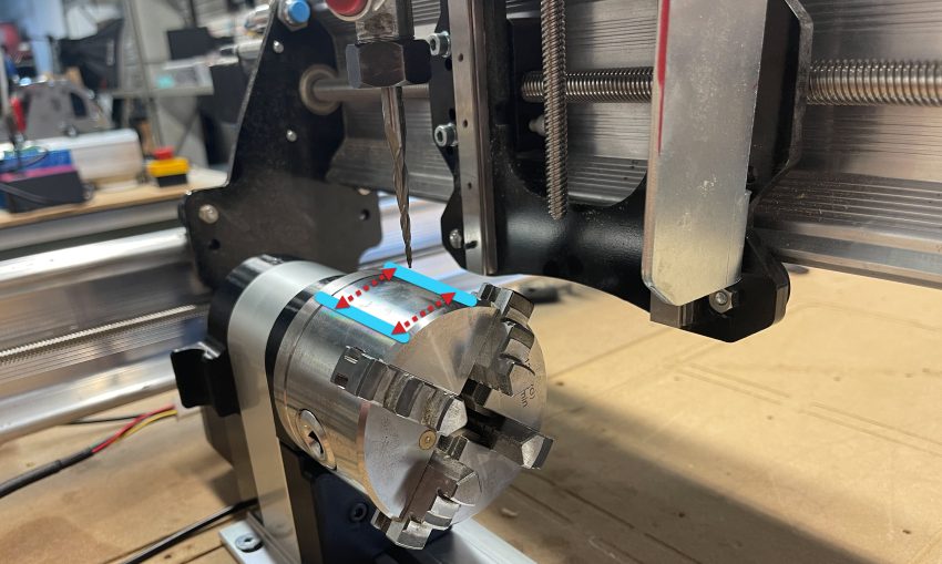
Install a V-bit or small ball-end mill (pictured) into your router then lift your Z-axis and jog your Y-axis towards the chuck on the headstock of the Vortex so the bit hovers just above the top of the chuck, just above it’s center of rotation/axis. As long as you are within 0.6 inches of the center, you’ll be good to go.
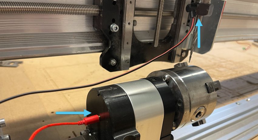
Next, with the probing wire installed into your controller, unplug your touch plate, then plug in the banana plug end into the rear-facing hole on the Vortex headstock and attach the magnet end onto your router’s collet.
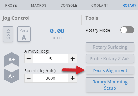
Select the ‘Rotary’ tab in the bottom right corner of gSender, but double check that your probing wires are connected.
Once you click on the ‘Y-axis Alignment’ button, the machine will immediately begin the probing cycle for locating the Y-axis center line. Be sure you are ready, as you don’t have the option to do a continuity check at this step.
Rotary Mode
With this finished, we’re now ready to switch the Y-axis motor output over to the Vortex, finalizing the Y-axis to A-axis conversion.
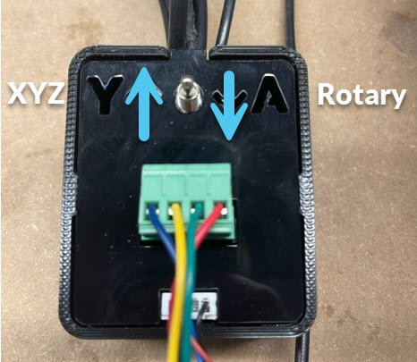
If your Y-axis motors don’t have power running through (in Firmware settings, either $1=254 or $37 Y-axis disabled) go ahead and flip the switch on your Vortex switchbox.
If your Y-axis motors are energized ($1=255 or $37 Y-axis enabled), there’s an extra step that we recommend taking to preserve the life of your components.
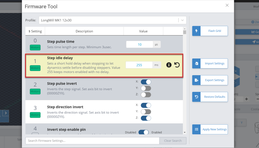
$1=255, energized
Extra Step:
LongBoard – Hit E-stop, flip Vortex switch, un press E-stop
SuperLongBoard – Hit E-stop, flip Vortex switch, un press E-stop, unlock gSender
This process will cause your motors to move slightly, but it will be negligible to the accuracy of your carving.
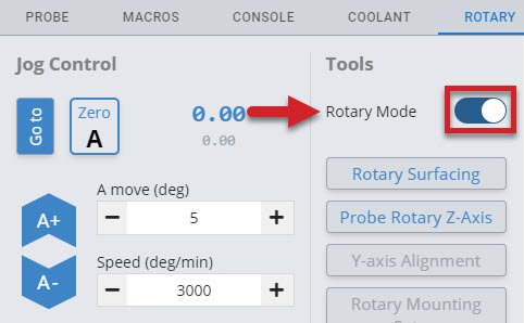
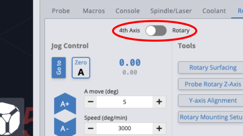
At this time you can power back up and enable ‘Rotary mode’ within gSender by selecting the ‘Rotary’ tab in the bottom right corner of the screen, then toggling the ‘Rotary Mode’ option found here.
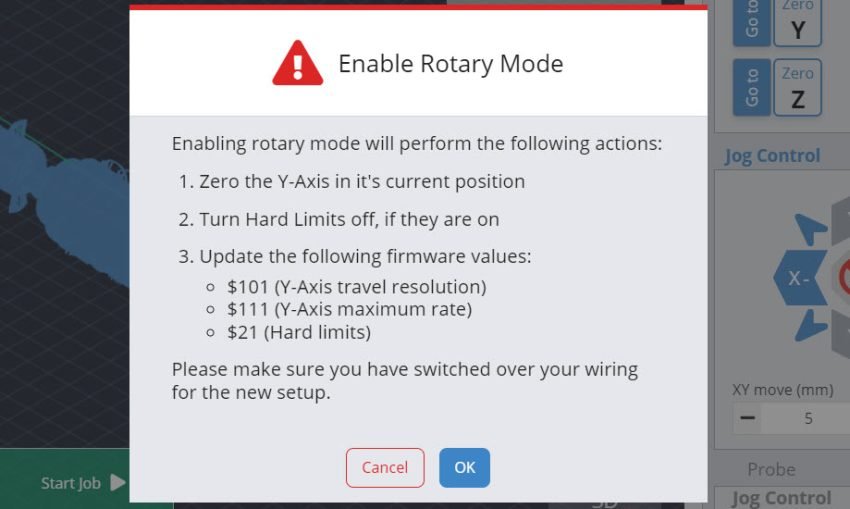
You’ll be prompted to ensure your output switchover has been completed before proceeding.
Load the g-code file you’ve just generated into gSender and install the appropriate cutting bit into your router for your project, in our case we’ll be using a ¼” tapered ball end mill like we setup earlier while generating our toolpaths.
4th Axis Mode
Make sure you have energized the A-axis. If you have a LongMill with a spindle, energize the Z-axis as well. To check, go to your Firmware settings and search for $37. If the axes are not yet enabled, toggle them and then press Apply Settings. Turn OFF then ON your controller to have the settings take effect.
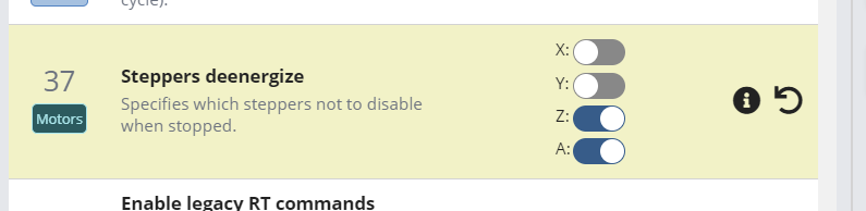
$37, Z and A-axis enabled
Reconnect to gSender and toggle into 4th Axis Mode. Stay in 4th Axis Mode at all times, do NOT switch to Rotary Mode.
Load the g-code file you’ve just generated into gSender and install the appropriate cutting bit into your router for your project, in our case we’ll be using a ¼” tapered ball end mill like we setup earlier while generating our toolpaths.
Setting X & Z axis
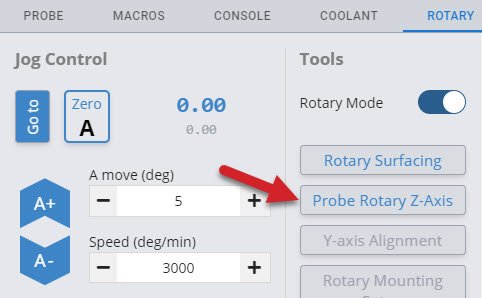
One of the last things we’ll need to do before we can hit ‘Start’ on this program is setting the Z-axis zero position. Since we’ve set the origin of this project to be at the rotating axis/center line we’ll make use of the Vortex’s built in Z-axis probing functionality.
To do this, jog the cutting bit to be hovering approximately ~15mm just above the chuck, just like we did with the Y-axis probing. Double check that your probing wires are in place before proceeding!
In gSender, select the rotary axis tab, then Click ‘Probe Rotary Z-axis’ and the Z-axis will begin probing automatically, setting the Z-zero point for you.
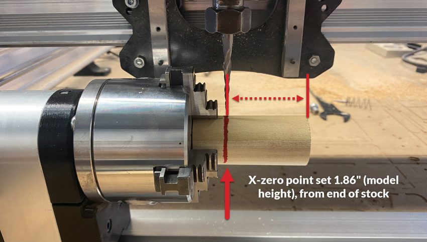
Next, jog your X-axis to wherever you’d like the job to start then click ‘Zero X’ to set your X-zero point. Make sure this is far enough from the chuck to ensure there won’t be any collisions with your cutting bit.
We’ll also want to make sure that this isn’t set too far to the right, causing us to cut air once we reach the end of the stock. Since we know our model length is 1.86”, we’ll mark out a line on our stock ~1.9” from the end, then set our zero here.
Since our A-axis zero position doesn’t matter in this case (and in most cases with rotary projects), we can set this zero point at the beginning of each job. Note that if this isn’t done, the rotary will spin back to zero before the job starts.
With all three axes’ zero points set, we’re ready to turn on our router and click ‘Start’! If this is your first project using the Vortex, keep a watchful eye for any strange behaviour and adjust the feed override while the project runs if needed.
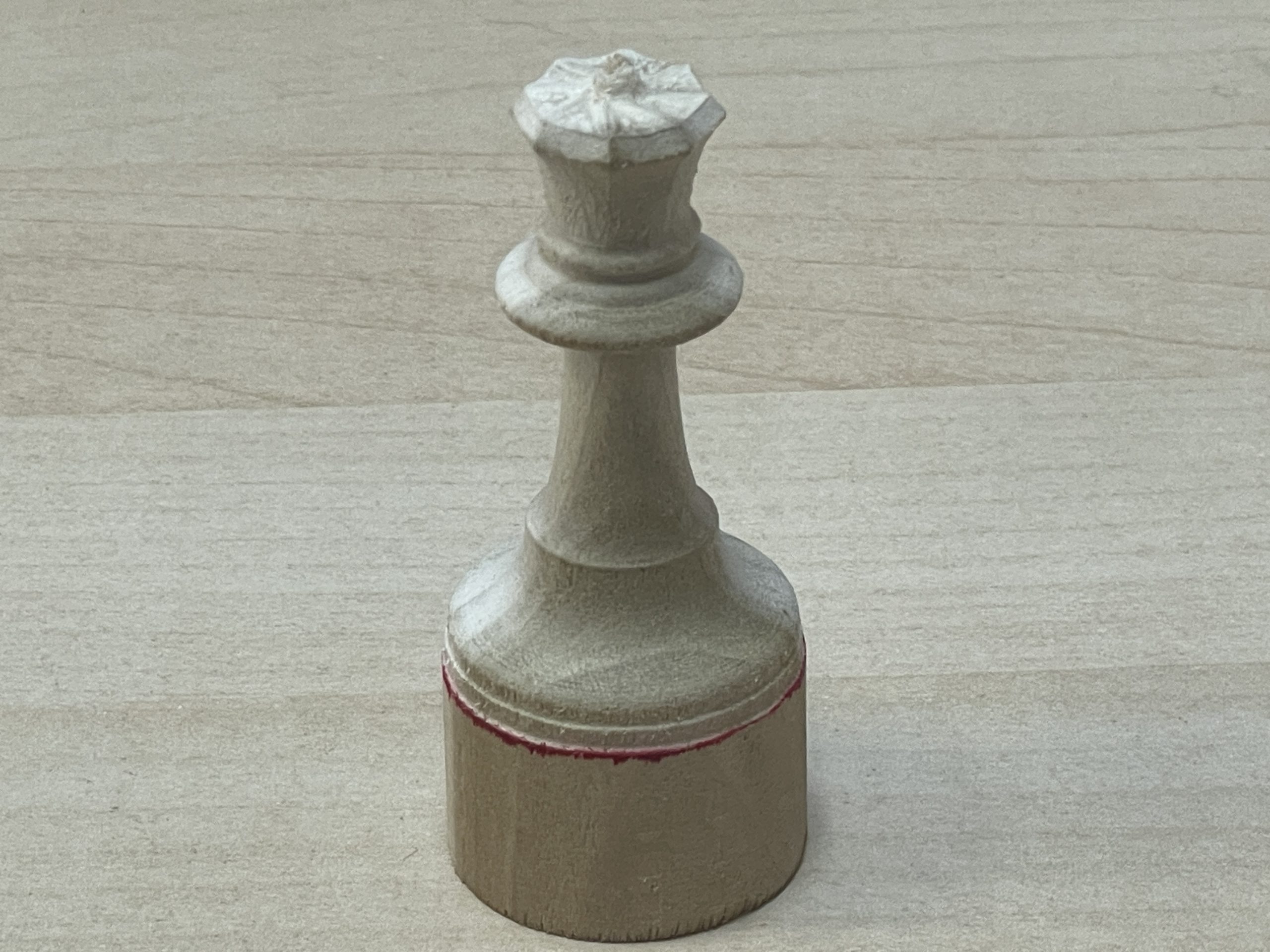
Once the project has completed, you have a couple choices.
- Remove your piece from the chuck, cut/saw off the bottom and admire your latest creation.
- If you have enough space, you can jog your X axis to the spot you want to cut, turn on your router, lower your Z axis into the wood, and spin the A axis to cut out your final piece.
Checkmate indeed!