
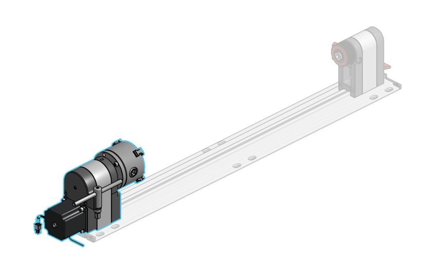
To start, we’ll be assembling the headstock. This will take approximately 20 minutes.
OR
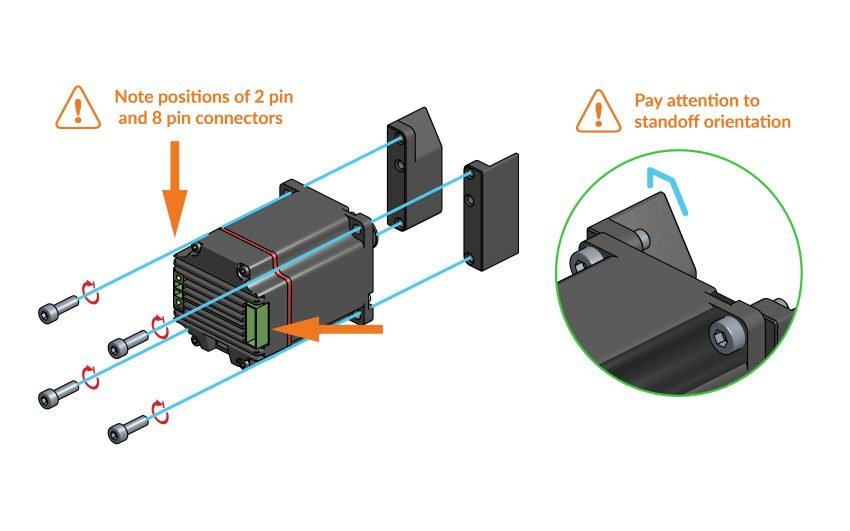
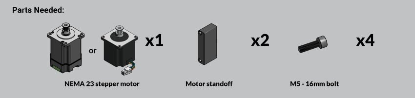
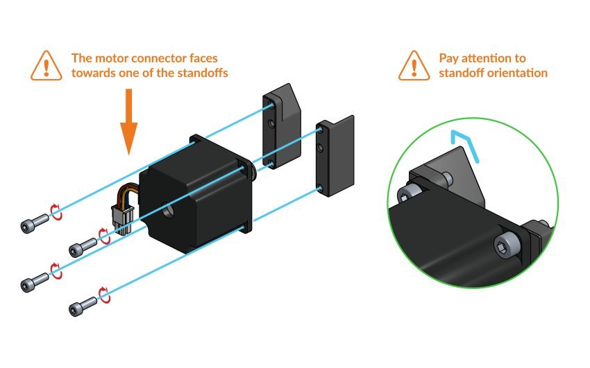
Align the motor standoff pieces with the four mounting holes on the stepper motor as shown (this is a tricky one to get right on your first try!) and secure them onto the motor using the four M5x16mm bolts. The round corners of the standoffs face the center of the motor. Depending on whether you’re assembling a ‘closed loop motor’ kit or ‘open loop motor’ kit, follow the above instructions as appropriate.
Make sure that the motor square connector is facing towards one of the two standoffs.
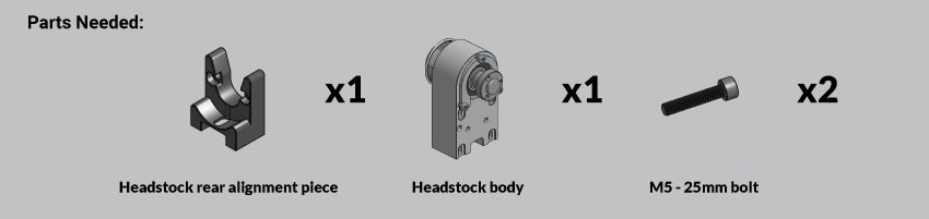
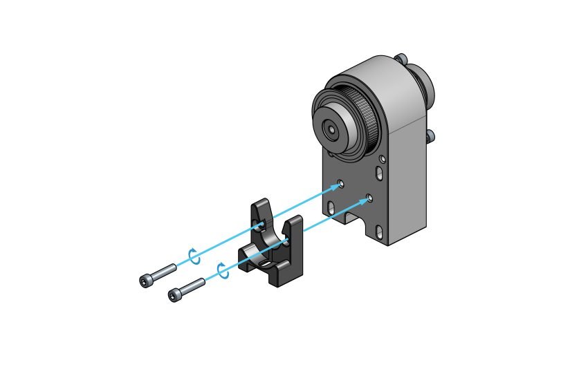
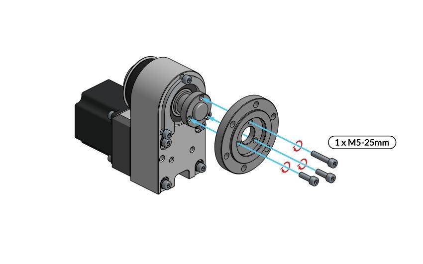
Secure the rear alignment piece onto the back of the headstock body using the two M5-25mm bolts.

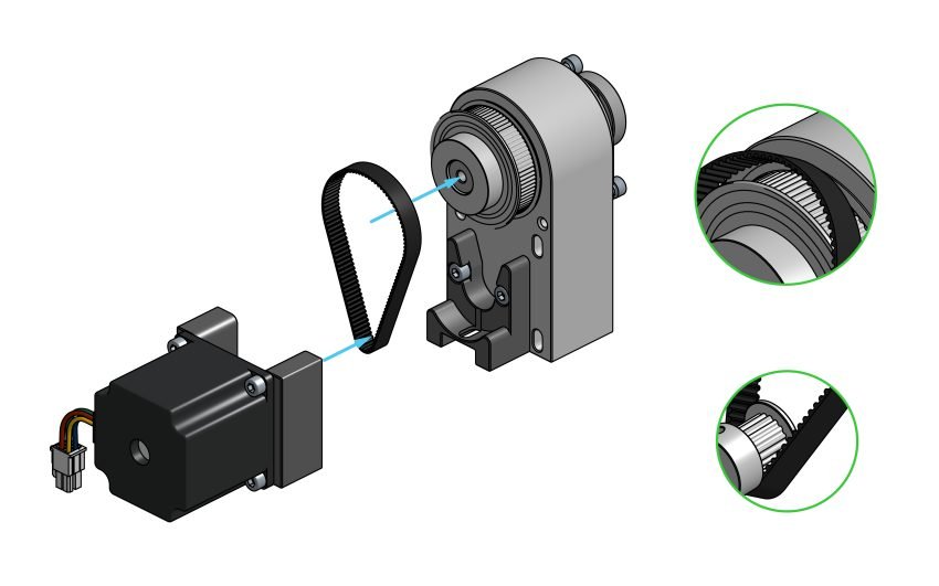
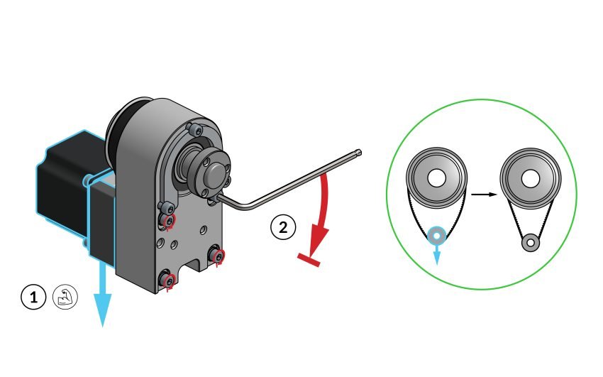
Loop the belt around the larger pulley on the headstock and snag it with the smaller pulley on the motor.
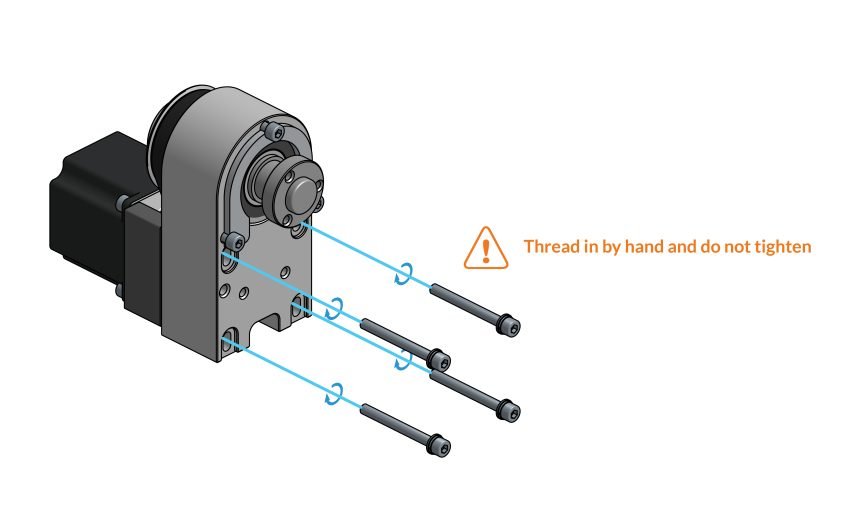
Pass four M5-50mm bolts through slots in the headstock body and thread the bolts into the motor standoffs.
Don’t tighten these yet, since we’ll need to tension the belt in the next step before fully locking them down.
Double check that the motor cable is facing the right or left side.
Tension the Belt
Using your thumb and index finger, press down on the motor standoffs. This will apply tension to the belt.
With the standoffs held down, secure the four M5-50mm bolts that we left loose in the previous step.
Test the belt to make sure it is tensioned properly.
Final Check
-
- Correct
-
- Incorrect
NOTE: To make this belt tensioning step easier, you can also try clamping the headstock body to your table or asking a friend to help hold it down, while you tighten the bolts.
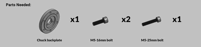
Secure the chuck backplate using the three M5 bolts. One of the three M5 bolts is longer and the choice of hole does not matter.
These bolts should be very tight.

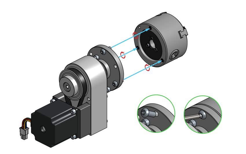
Position the chuck so that the bolts line up with the threads at the back.
Insert three M6-16mm bolts into the chuck backplate, spaced out evenly in a triangular pattern.
Tighten each bolt a little at a time and rotate in between bolts to ensure even tightening. You will also want to use a ball-ended Allen key (included in your kit) to tighten these bolts with the key angled away from the headstock body.
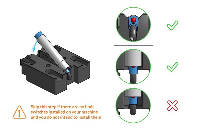
You won’t need to perform this step if you don’t have limit switches installed on your machine and aren’t planning on installing them anytime soon, but you’ll still need to attach the front alignment piece in the next step. If you do have limit switches, then carry on.
Push the switch up against the stop in the alignment piece and push down firmly to secure the switch (You can push it against the table to snap it in place).
Make sure that the LED light at the end of the switch is facing up when you install it.
If you need to realign the switch, you can make use of the opening under the sensor cutout and pry the switch out with an M5 Allen key. Do not try to remove the sensor by pulling on the wire, as this may damage the sensor.
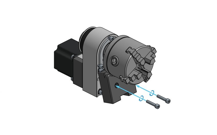
Slip the front alignment sub-assembly underneath the chuck and secure it with the two M5-25mm bolts.
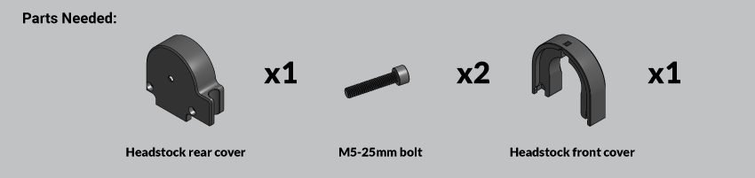
Slip the rear cover onto the headstock in between the motor standoffs and secure with two M5-25mm bolts.
Gently tighten the bolts since you may damage the plastic piece if overtightened.
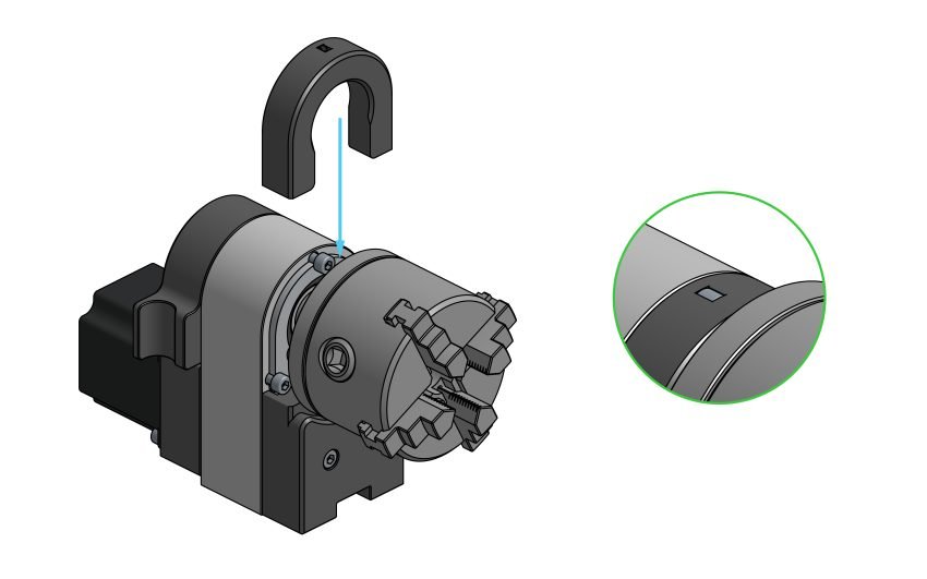
Slip the front cover onto the headstock. The cover should latch onto the heads of the bolts on the front of the headstock body.