Check out our video on how to mount your Vortex!
The video below shows the Open Loop Vortex. For Closed Loop Vortex, at timestamp 17:18, use 4th Axis Mode instead of Rotary Mode on gSender. Closed Loop Vortex must use 4th Axis Mode at all times!
We’ll use the Longmill to make its own holes for threaded inserts that will allow us to mount the track. This way, we can guarantee that the Vortex will be aligned correctly.
-
- Installing threaded inserts
-

- To mount the Vortex
Preparing Your Machine
The Vortex rotary axis requires a minimal amount of space on and above your wasteboard to function properly. So before you start putting holes into your wasteboard, let’s double check your setup and make some adjustments to maximize compatibility.
Flat Area on Your Wasteboard
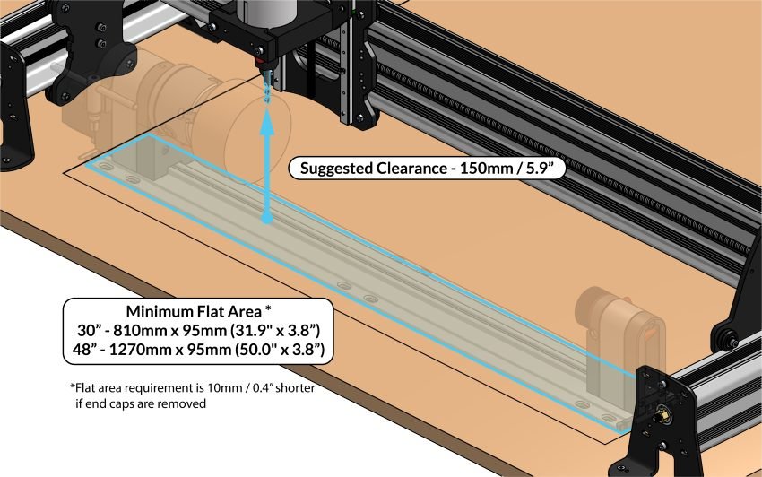
The minimal flat area needed on your wasteboard is 810mm x 95mm (31.9″ x 3.8”) in size for the base configuration, and 1270mm x 95mm (50.0″ x 3.8”) with the extension.
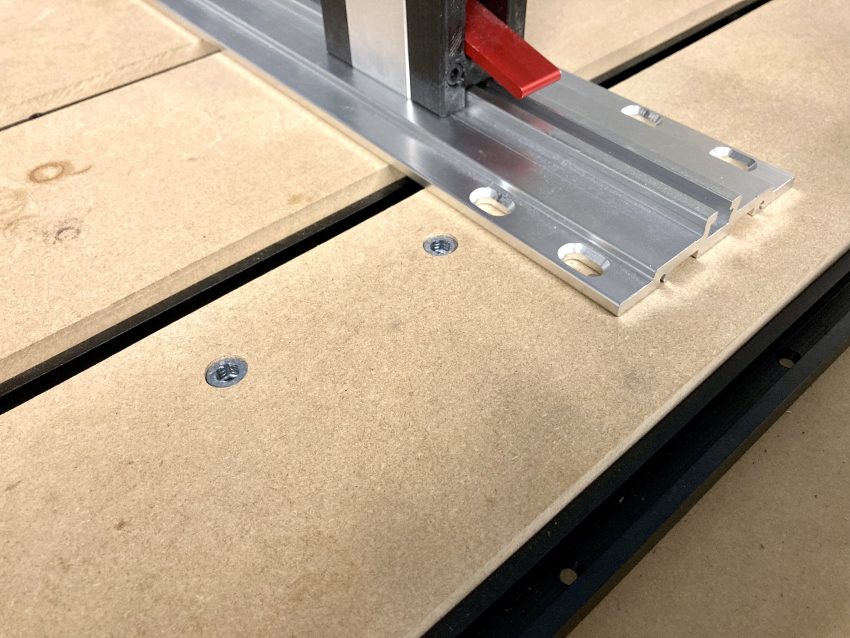
You can easily check if the surfaced area on your machine is at least this size by placing the Vortex track on top of your wasteboard and seeing if the track ends hang outside of this area. If this is the case, you will have to resurface your wasteboard to a larger size. If you remove the end caps of the track, you will reduce the space needed by 10mm.
Here the track is outside of the surface area
If you have a longmill MK1 dust shoe, your surface area may be limited by the dust shoe bracket. See the section specific to the MK1 below to learn what to do.
Setups With Raised Wasteboards
The Vortex requires 150mm (5.9”) of height clearance from wasteboard to tool in order to carve a 4” diameter piece of material.
If you have an additional piece of material atop the base of your machine, this will reduce your cutting envelope to below 4” diameter and create difficulty using the Y and Z axis probing features in gSender.
If you have such a setup, we recommend that you raise the feet of your machine, or remove your wasteboard.
-
- MK2
-
- MK1
| Configuration | Issue | What to do to improve clearance | Illustration |
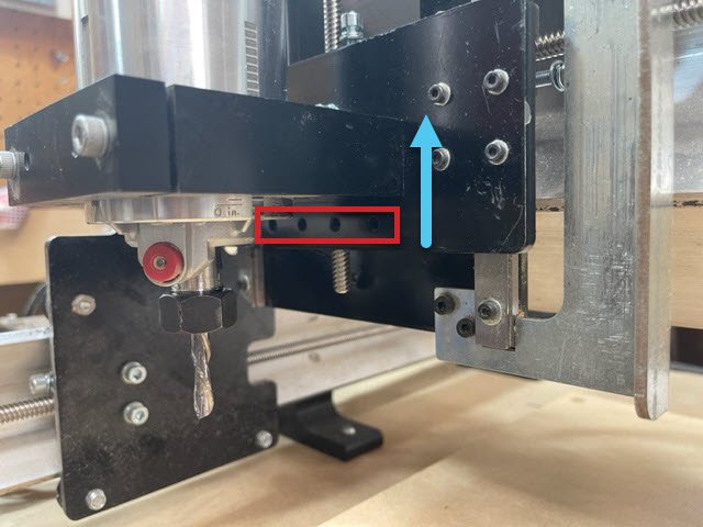
| Lower router mounting | ⚠️Under 4” cutting volume
⚠️Difficulty using the probing feature in gSender to zero the Y and Z-axis. |
Move to top router mounting
Illustration shows correct position |
 |
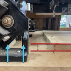
| Dust Shoe bracket | ⚠️Under 4” cutting volume
⚠️Insufficient surfaced area on waste board to fit the track |
To cut the full 4″ volume, the dust shoe bracket will need to be removed.
Remove the bracket before re-surfacing the wasteboard and installing the threaded inserts. Illustration shows short wasteboard due to bracket |
 |
gSender
We will be using the latest version of gSender to create your mounting holes. Simply click the link to navigate to the downloads page.
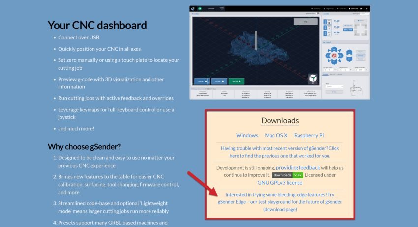
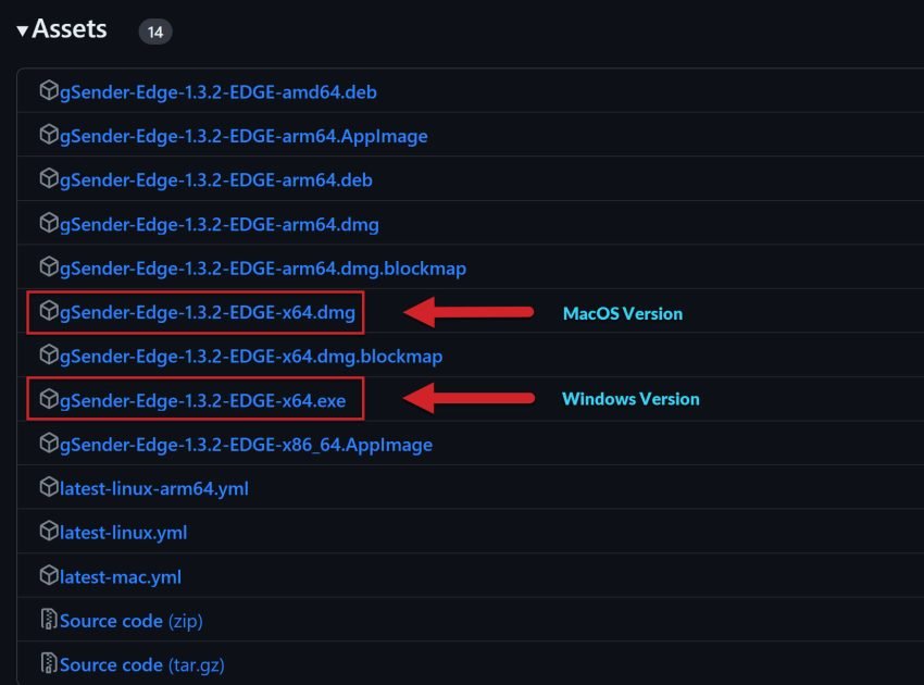
Once on the gSender Edge download page, select the file that matches your operating system and click to download it.
Once downloaded and installed, navigate to Settings where you will find the Rotary tab.
Here you can hide or display the Rotary tab on the main page.
For Open-Loop Motor Kit, toggle to Rotary Mode. For Closed-Loop Motor Kit, toggle to 4th Axis. Do Not Use Rotary Mode
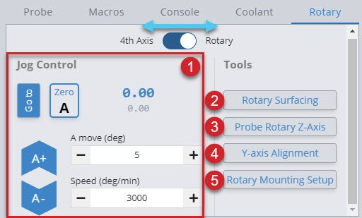
With this tab you can:
- Jog Control – Rotate the A-axis, go to Zero, set Zero, and adjust speeds
- Rotary Surfacing – Wizard to turn square stock round
- Probe Rotary Z axis – Automatically probe to find the Z axis
- Y axis Alignment – Automatically probe to align the Y axis along the A axis (Turn rotary mode off to access this feature)
- Rotary Mounting Setup – Drill holes in your wasteboard to mount the track (Turn rotary mode off to access this feature)
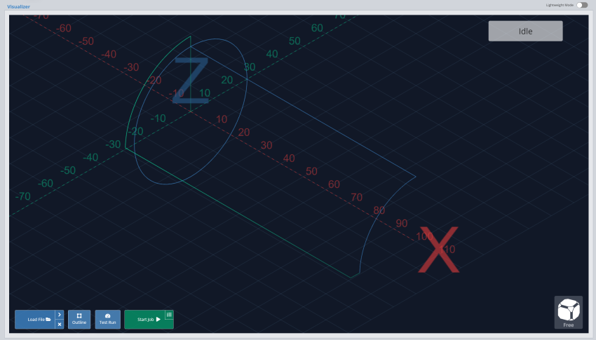
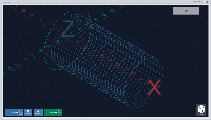
As gSender Edge is our test arena for working on new and exciting gSender updates, there are a couple current limitations.
In the visualizer, the stock turning tool is missing the helical toolpaths. You will see the image on the left, but rest assured, the toolpath is following the image on the right.
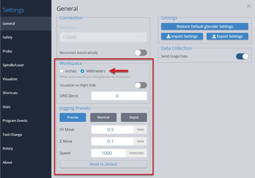
For your Workspace, you will need to select millimeters and not inches for now as well.
Creating the Mounting Holes
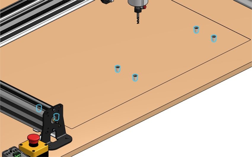
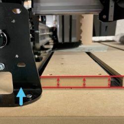
Lay the mounting track (and extension track if applicable) across the wasteboard of your LongMill positioned where the track sits behind the inside edge of the front feet on your LongMill.
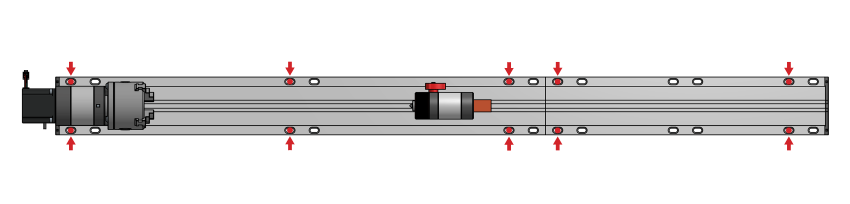
With this in position, check to see if there are any interferences between any T-tracks or other workholding systems you might have, and the ‘default’ sets of holes highlighted blue in the illustration below.
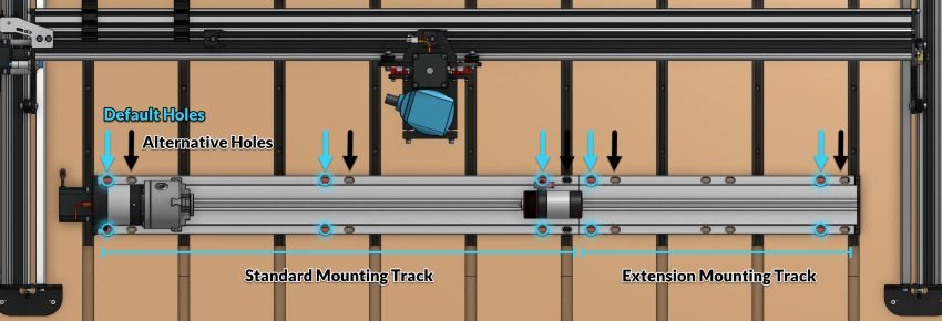
If there’s no interference on your table with the default mounting hole positions, mark the center of the far bottom left hole with a pen/pencil.
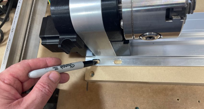
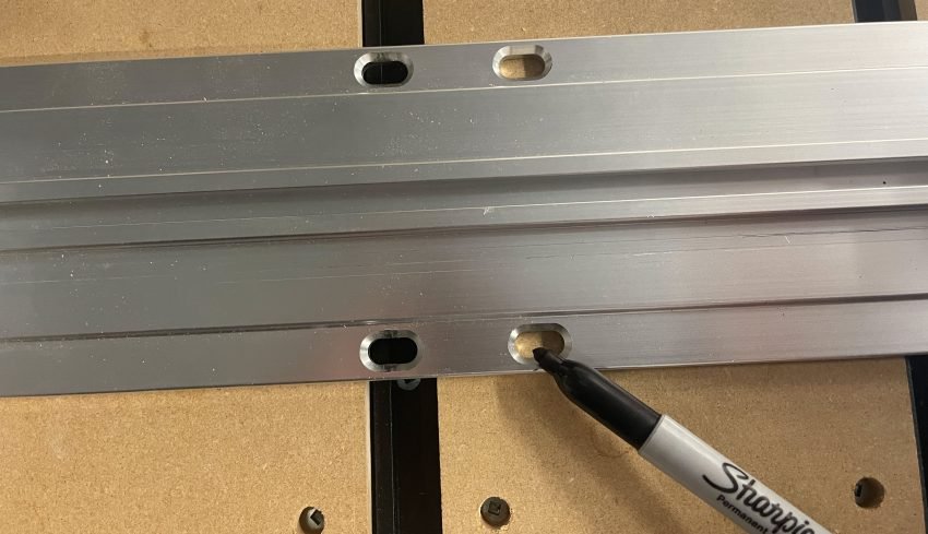
If you’re unable to use all the default mounting holes, mark the bottom hole for each pair of holes which do not interfere with anything on your wasteboard.
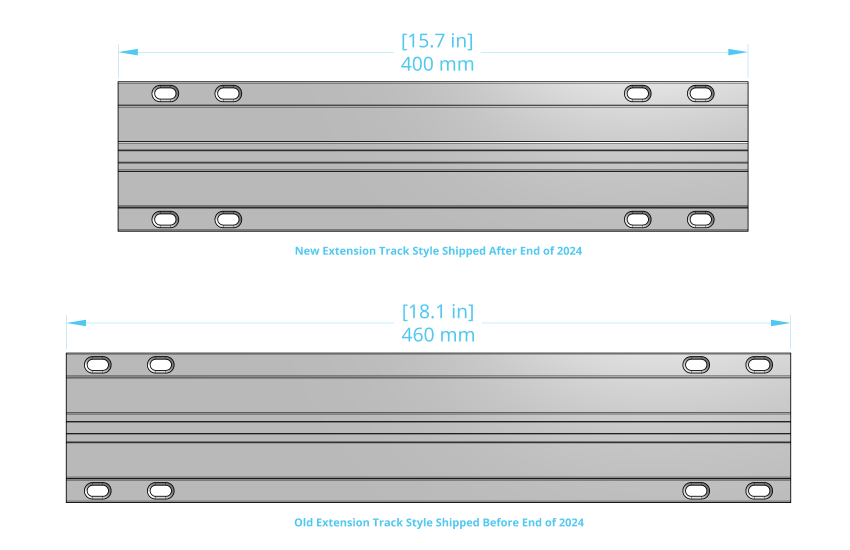
Note that the Vortex extension mounting track was revised near the end of 2024 to allow for compatibility with closed loop motors. If you received your kit near or after this time, you will likely have the updated track that is 400mm in length.
At this time, using the updated ‘400mm extension track’ requires that you mark the individual bottom holes of each pair, and follow the ‘Custom Mounting’ instructions below.
With all this planning out of the way, it’s time to make some holes!
First things first, open up gSender and connect to your LongMill. A best practice when mounting the Vortex is to ensure your X-axis is square. Running your Y-axis all the way to the front or back of the machine until you hear each rail hit the end, will ensure you are square and ready to proceed.
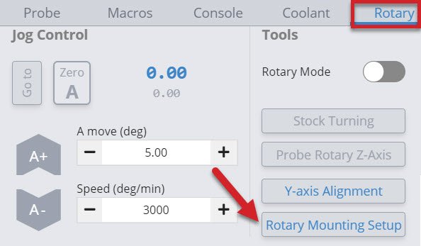
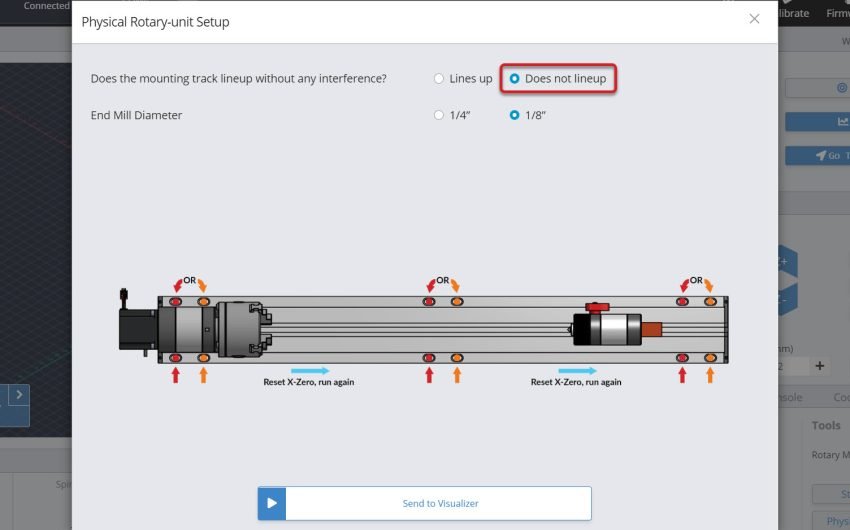
Select the rotary axis tab on the bottom right corner of gSender, then click ‘Rotary Mounting Setup’ to open the selection window displaying each of the different track setup options.
Which setup you’ll choose will depend on three selections:
- Does the mounting track lineup?
- Are you using a ¼” or ⅛” diameter end mill ? (Make sure the router is mounted as far down as possible with the bit inserted not too far into the collet if using a ⅛ bit, to prevent your Z gantry from bottoming out.)
- Do you have the extension?
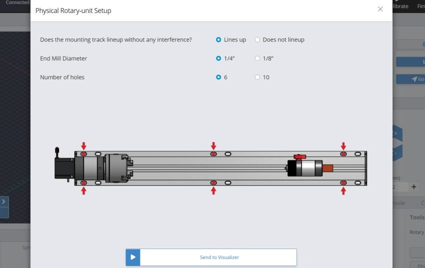
Select the buttons that match your circumstances, and hit the Send to Visualizer button.
Default Mounting
Lucky for you, If you’re able to use the default mounting holes, you’ll have a very simple procedure to follow.
OR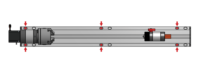
Simply jog your machine/cutting bit to be hovering right above the point you’ve marked previously and set your X and Y position to zero. Use any method such as touch plate, paper method, etc. to set your Z-zero position to the top of your wasteboard at this marked spot.
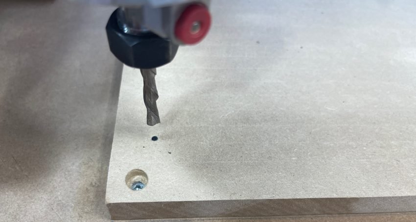
Turn on your router and run the g-code program you’ve loaded. Either 6 or 10 holes will be milled into your waste board automatically.
Custom Mounting
If you find a t-track, dog hole, threaded insert or even the screws holding down your wasteboard will interfere with the default mounting holes, you can use the custom ones. Selecting Does not lineup will generate g-code code that drills out one pair of holes at a time.
By marking each set of holes that are clear of interference with a pen, you will have a great reference point to set a new X-axis point for each set of holes you are going to drill.
For this approach, we’ll first jog our cutting bit just above the first marked hole on the bottom left most corner, then set our X, Y position to zero here. Use any method such as touch plate, paper method, etc. to set your Z-zero position to the top of your wasteboard at this marked spot.
Turn on your router and run the program. You will drill out the first, then second hole.
Once done, turn off the router and jog your machine’s X-axis so it’s centered just above the next marked hole position. Set your X position to zero, leaving your Y and Z zero position unchanged. Turn on your router then run this same g-code file again.
For every remaining set of holes to the right, continue jogging rightwards, resetting the X-zero position, and running this g-code until all sets of holes are done.
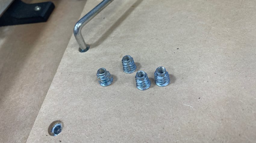
With all these holes made, we can now proceed with installing the included steel threaded inserts using either a 6mm or 7/32” allen key.
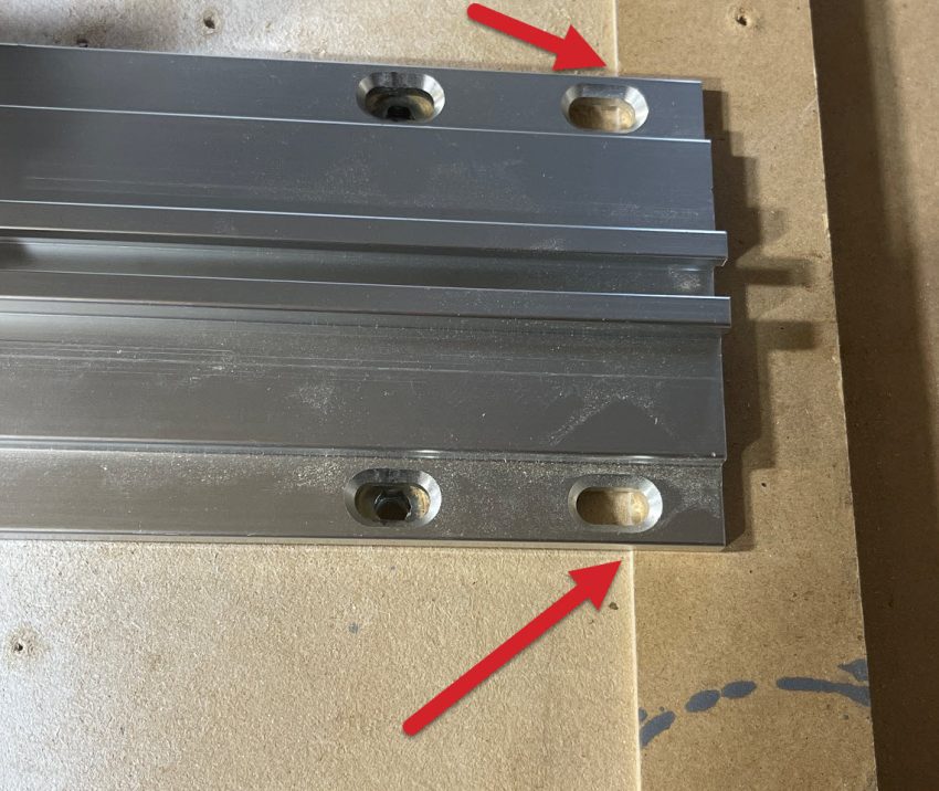
To mount the vortex to your table, simply lay the Vortex mounting track across your wasteboard, lining up the mounting holes with their respective threaded inserts. If you have a 48” X-axis LongMill and will be using the Vortex extension track, align this track up against the end of the regular mounting track.
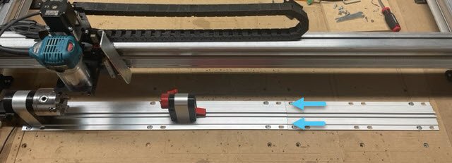
Install 6 of the included 1/4-20 – ¾” flat head mounting screws into the appropriate holes of the regular mounting track, tightening these to be snug.
An additional 4 screws will be used for the mounting track extension.
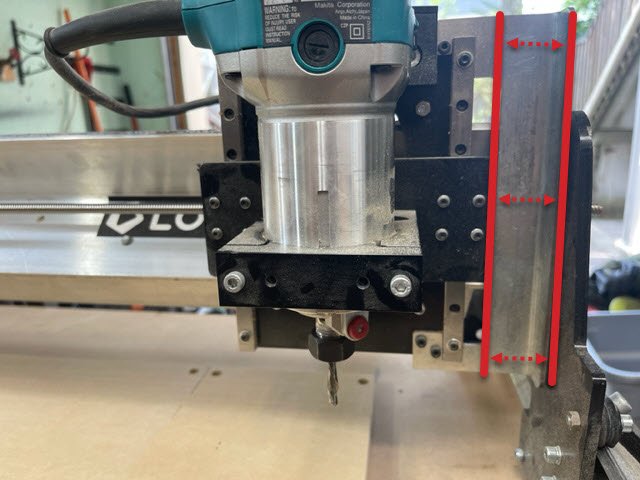
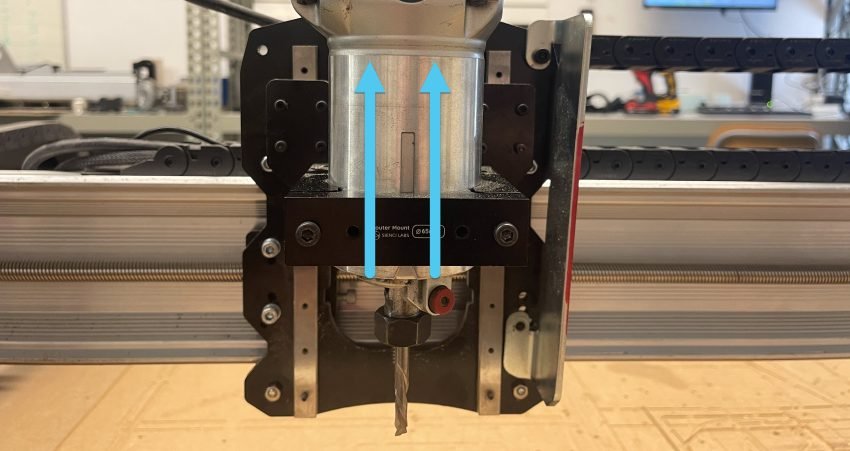
As a last step, you’ll most likely want to loosen the screws on your router mount and slide your router upwards so it sits higher. Since most of the work we’ll be doing with the Vortex will demand that your cutting bits sit about twice as high as normal, it’s convenient and sometimes necessary to raise where your router sits inside the router mount.
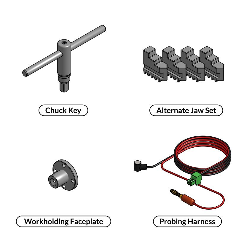
Well done! Now that we’re finished with assembly, you’ll find a few parts remaining unassembled. They are for you to use with your Vortex.