So you’ve finished your first project and are ready to move onto carving more intricate things? This ‘intermediate’ project will guide you through creating a rotary carving feature with much more detail and complexity, while helping you learn the tools and skills to carve almost anything!
We’ll cover several key concepts in this project, including:
- Fundamental Limitations of rotary carving
- Setting up Tabs
- Tool changing to use a roughing and finishing strategy
- Advanced Workholding
- Stock Turning
To complete this project, we will be using:
- A 4” long piece of stock with a diameter of 2.5” which we’ll make ourselves
- 3D skull file
- VCarve Software
- ¼” upcut end mill for roughing
- Roughing Pass g-code file
- ¼” tapered ball end mill for finishing
- Finishing Pass g-code file
- gSender
- LongMill with Vortex attachment
Model Selection
A big misconception of rotary carving is that only round objects are suitable. It’s completely natural to attribute round things with a process that involves spinning, but rotary carving with the use of a CNC machine is quite unique.
Since we have full independent control of all three axes, we can do a lot more than a simple chess piece. The reason projects done on a rotary axis tend to be round or cylindrical in nature is simply because these are the types of projects that fit best within the footprint of a rotary axis. It’s just as feasible to turn a cylinder into a cube on a rotary axis as it is to turn a cube into a cylinder.
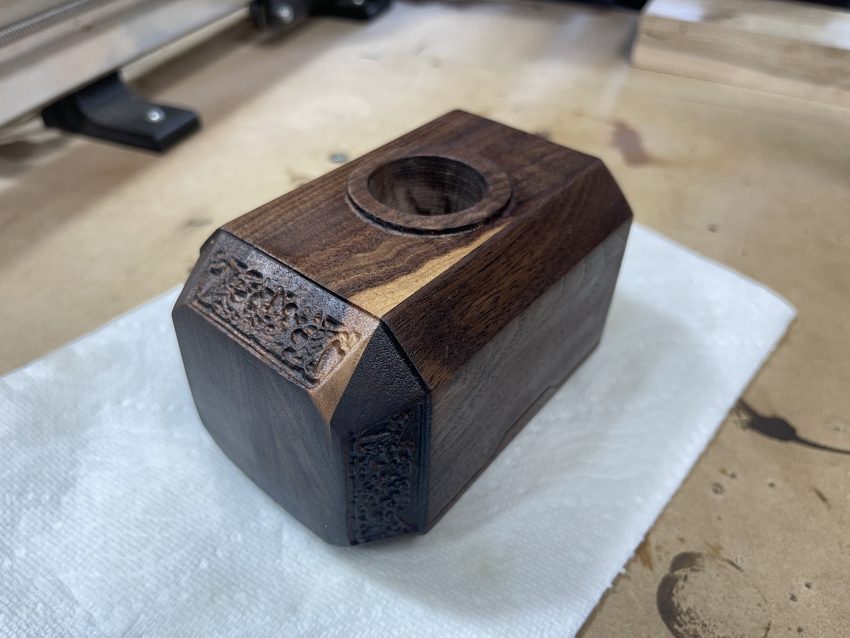
Thor’s hammer completed on the Vortex. Making round things square!
On that note, for our second project, we’ll be carving something quite a bit more complex than the chess piece we did on our first project. This will be a skull which is asymmetrical (think lopsided, crooked or unbalanced) around any axis, and features tiny details and cavities.
Limitations of Wrapped Rotary Carving
We mention that we’ll be able to make any sort of shape using a rotary axis, and this is generally true, however there are some caveats and limitations to this. Two limitations to be aware of are overhangs, and trying to machine below the middle axis.
Overhang isn’t necessarily a limitation new to rotary axis carving, it’s something we’re limited by in any regular XYZ carving, but is a bit more apparent once we’ve taken this same carving and wrapped it around an axis for rotary carving.
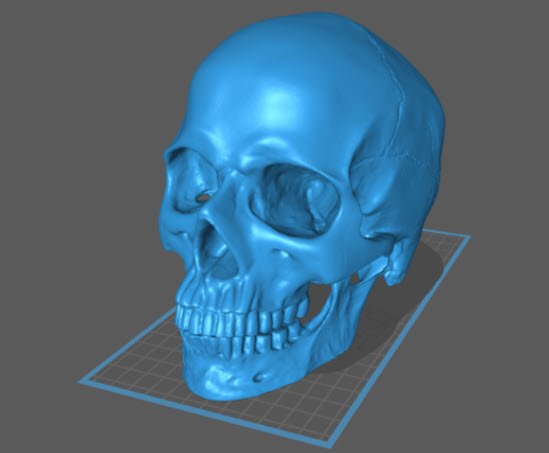
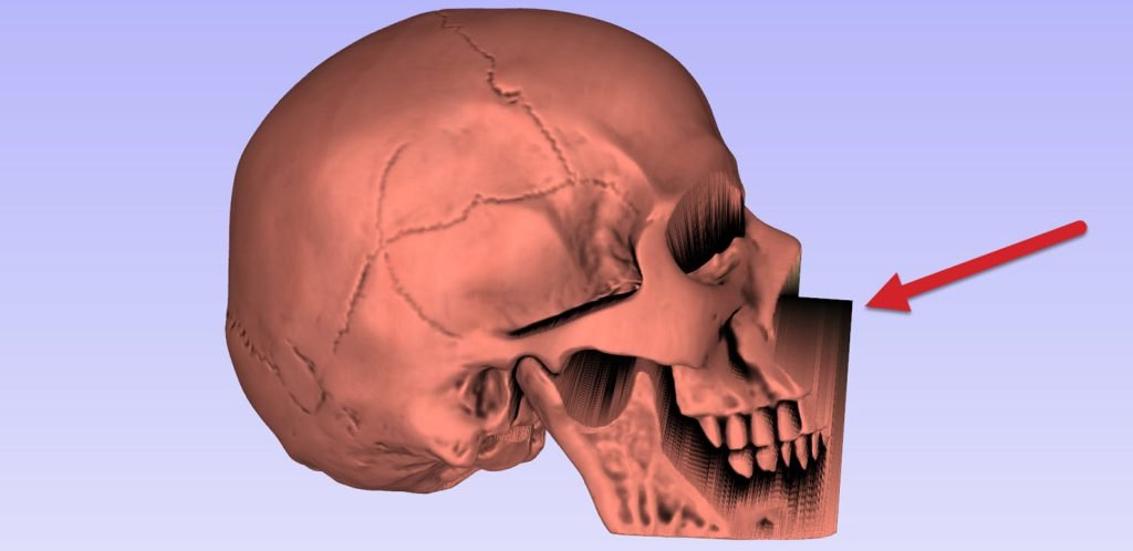
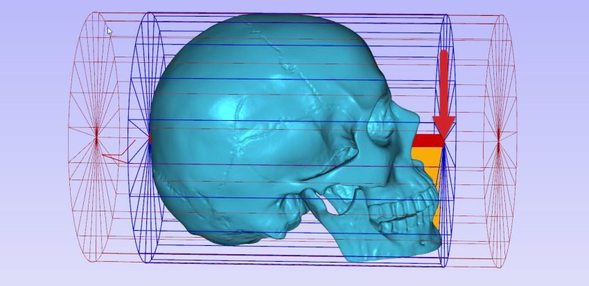
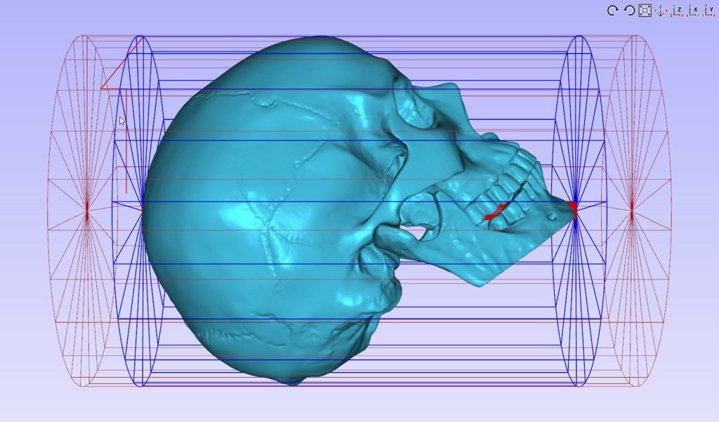
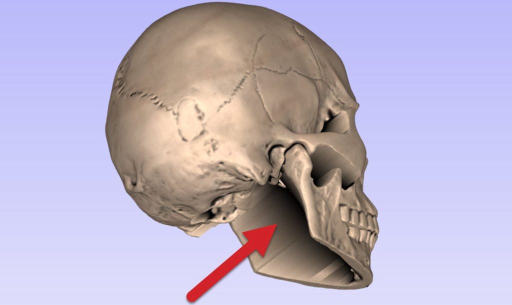
If we simply import this 3d model without any repositioning, you can see that we will have a large overhang marked in yellow in the image below. This results in a model that is missing a lot of detail.
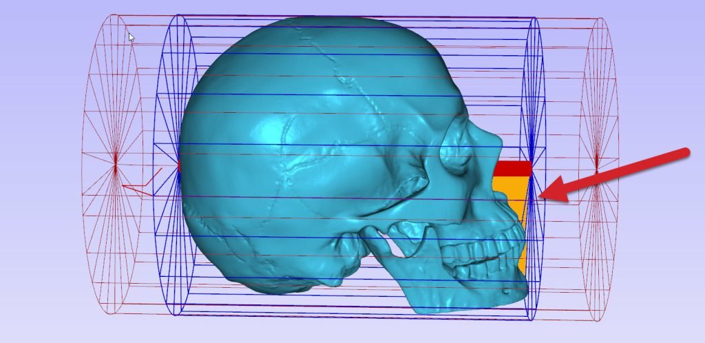
Since our rotary carving is essentially a regular 3-axis carving wrapped around a single axis, we have the same limitations as before – this means no overhanging geometry that our tool won’t be able to reach from directly above.
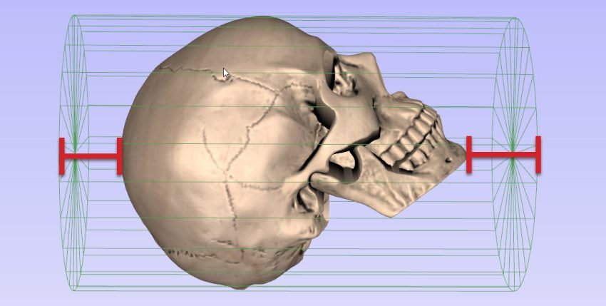
We can see a red cylinder passing through the entire model, showing us the current rotating axis relative to the model’s orientation.
The question is of course: where should this red cylinder lie relative to our model? Simply put, this red cylinder should ideally pass through as much of the model as possible, across its entire length. Any section where this red cylinder sticks out from outside the model, there will be an unmachined area below.
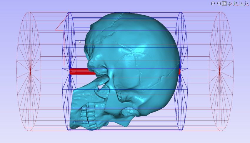
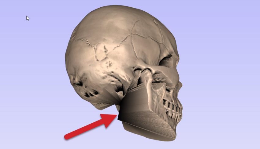
If we rotate the model on the Z axis, we can raise the chin, allowing the bit to maximize its coverage. This way we produce a clean front to the model and eliminate our overhang. In the example below, we rotate the model and then resize it to fit our stock. Overhang eliminated!
It’s also important to remember that since we’ve wrapped our model around an axis, the actual axis represents the bottom of the model as far as the machine is concerned, therefore we won’t be able to machine below this.
Where the chin of the model prevented us from carving out the overhang, the middle of the model limitation prevents us from coming at the overhang from above. We can’t go lower than the middle axis.
Sometimes these limitations might be small details you can clean up by hand after the fact, or they may force you to choose an entirely different model.
Sometimes this is more of a fundamental limitation, like being unable to carve out the slots inside this dagger blade completely. This was finished after the carve, by hand.
With all this in mind, we’ll move on to creating our project in VCarve.
Generating g-code
Just like in our first project where we made a chess piece, we’ll start out by sizing our project in the job setup tab, as well as of course selecting this as a rotary job type. We’ll then go on to import our model for this carve.
Optimizing Your Model’s Orientations
Like we’ve just gone over previously, we’ll want to orient our model in a way that allows us to machine most overhanging features, or at the very least – the overhanging features we care about most.
In our case with the skull, we have a few options for orienting the model – each with their own result. Obviously, there are many more options than shown below, but we’ll go through the 3 most obvious options below:
Option 1 – Skull model oriented sideways (A-axis is the red cylinder going ear to ear)
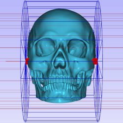
This option allows us to get just about all geometry carved, but won’t be very efficient in terms of fitting this skull into our material. You’ll usually find that finding round stock of a certain length is much easier than finding stock of a certain diameter – we generally prefer to orient models in a way that will maximize the utilization of the length of stock we have. Since this skull model is quite a bit longer than it is wide, we’ll prefer to orient this model differently.
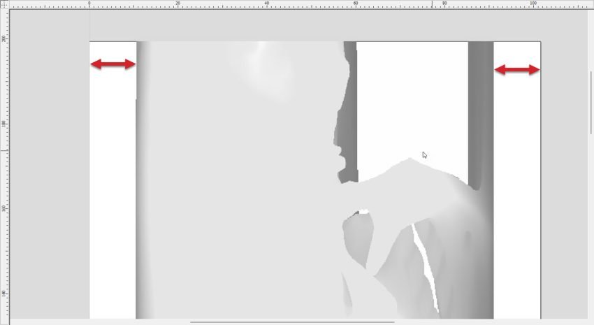
Option 2 – Skull model is oriented in it’s longest orientation (A-axis is going from chin to back-top of skull head)
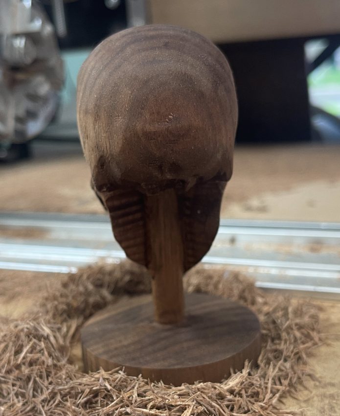
By passing the A-axis through the longest section possible, which is the path from the chin to the top of the head, we’re able to make this model as large as possible. This orientation also allows us to machine almost all of the important front-facing features such as the teeth and nose. There will be unmachined areas at the back of the skull behind the jaw, but of course these areas aren’t all that important so we’re okay with this detail missing.
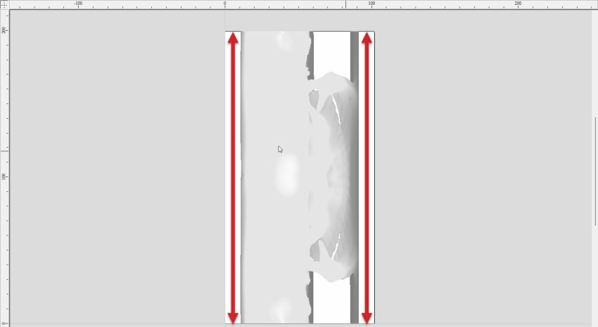
Option 3 – Skull model is oriented looking down (A-axis is passing through direct bottom to top of skull, sort of how a spine would be oriented)
This last option is not all that different from option 2, but has the skull oriented in a more ‘upright’ orientation across the A-axis. This doesn’t change much in our model fundamentally, but we start to notice some areas have an overhang, with more unmachined material at the back of the skull.
This orientation may be the best for exposing as much of the detailed face as possible, allowing for great detail, however we are using this example to show a large overhang you may want to avoid. You may opt for this orientation for your project, as the skull is more upright.
Asides from this, we’ll utilize a bit less of the length of the material which means we’ll end up with a slightly smaller scale finished model.
Given our three main options for orienting this model, we’ll be going with option #2 for this project, since it gives us the best results overall, as well as enlarging the scale of this model as much as possible.
Adding Tabs
In our first project carving a chess piece, we were able to hold this chess piece from one end, while the model was machined from left to right. This is because the widest part of the chess piece was at its base where we held the model in the chuck.
The skull model is quite a bit different, since both the left and right ends taper into a much smaller point from which we can hold it. This time around, we’ll approach holding our model by using what we’ll call Tabs. These are a bit like the tabs you might use while cutting our parts from a sheet of material in regular XYZ cutting, since they serve to hold the model in place as it’s machined to its final form.
You can see the space where we will be putting in our tabs below. These will fill up the remaining space of our stock material which sticks out from our model.
Although this project is using a tailstock and tabs, with a model this short, you don’t really need them. We wanted to show you this concept as an example in this project, but you may quickly realize they aren’t really needed with small projects like this.
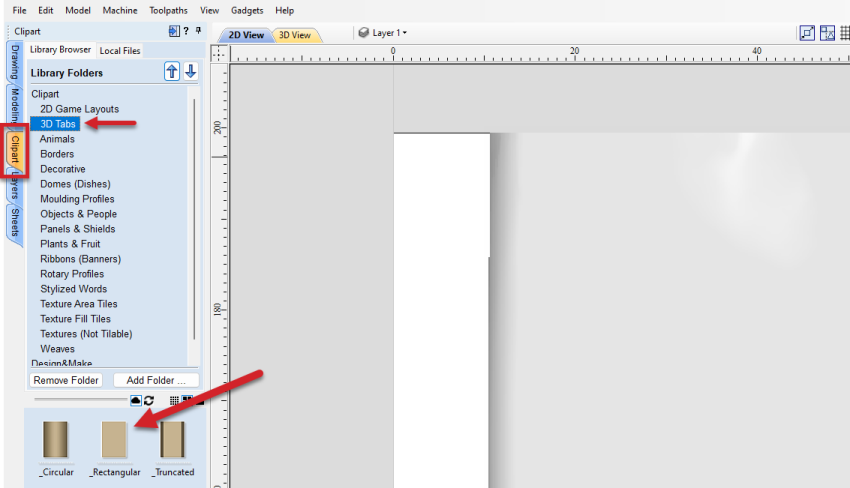
When looking at the 2d view, you will see your model in the middle, with a white border on each side. This is where we will be adding our rectangle tabs. Ensure that the tabs reach the entire width and length of the material.
Navigate to the Clipart tab, and you will see a Library Folder called 3D Tabs. Select this folder and then click and drag your _Rectangular tab icon to your 2d view.
Reposition it to ensure that it touches the edge of the project, and the project itself.
With two tabs in place, you can see our model is now supported on both sides. You can adjust the spacing and size of the tabs to ensure you have a firm hold on the model, while at the same time, reducing the amount of material you will have to remove once the carve is done.
Full Length Single Tab
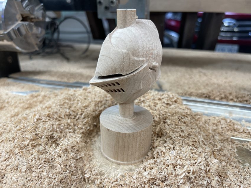
We can also add a single tab that runs along the entire length of your model. This is great if you are using a hollow model or looking to have a bust display.
Drop your ‘_Rectangle’ tab on your 2d model again, but this time, we will make it cover the entire workspace, then click on the component properties to downsize it and reveal our model.
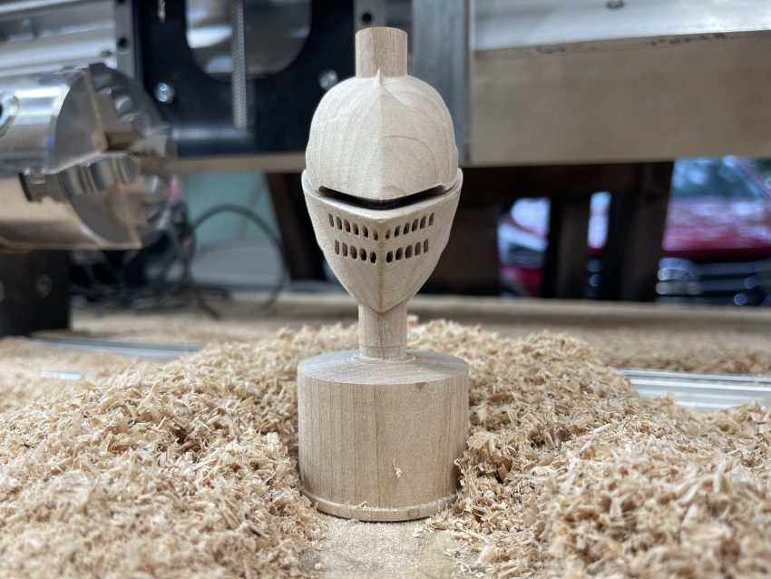
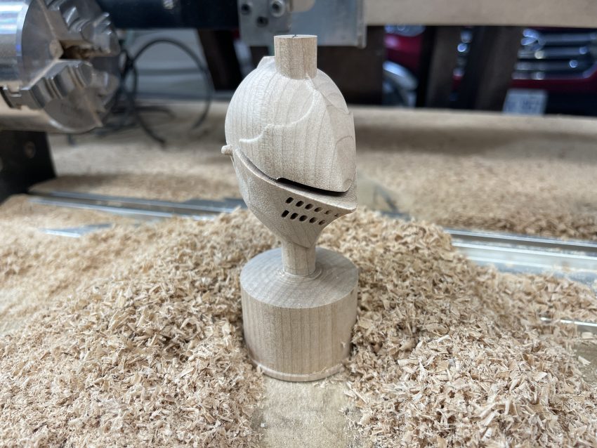
This is helpful to give a hollow model a ‘bottom’ to prevent the end mill from trying to carve out below the center axis. In the example below, we have a model of a knight helmet which is completely hollow inside. The full length tab serves to hold the piece in place, and give us something in the center of our hollow model to prevent the bit from trying to machine all the way through.
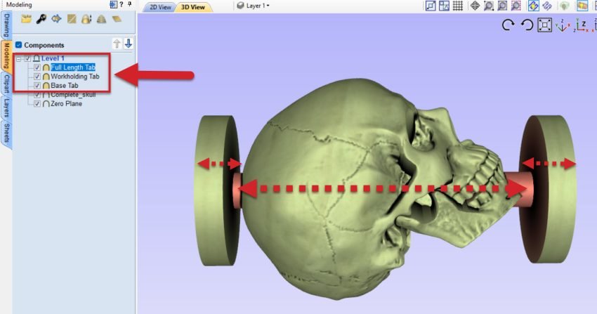
This is what our final skull tabs look like:
- Full Length tab that serves as a spine and connects the Workholding and Base tabs.
- Workholding tab that protects the faceplate and screws at the top of the model.
- Base tab that secures the bottom of the model in the tailstock, and holds the full length tab in place.
Generating Toolpaths
A larger stock size will typically take longer to carve, so for this project we’ll use a roughing path strategy before we run our finishing toolpath. This is really no different than regular XYZ 3D carving, where you’ll typically use a roughing pass on larger projects to save some time and reduce the load on your finishing tool.
In our first project where we made a simple chess piece, we were able to get away with carving this without any roughing pass, this is because we were able to have the bit enter the material from the base of the chess piece, and only remove a small amount of material at a time.
This time around, the bit will be milling away lots of material at both the bottom and top of the model so we’ll need to have a Roughing pass and then a Finishing Pass.
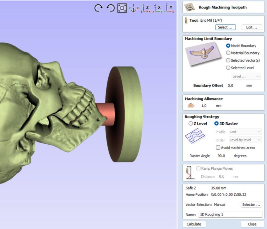
Select the roughing pass toolpath icon.
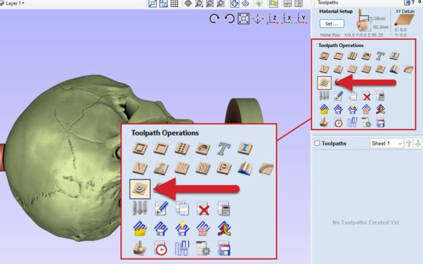
And select Model Boundary with a 3D Raster roughing strategy. We will enter 90 degrees to carve from right to left, along the A-axis.
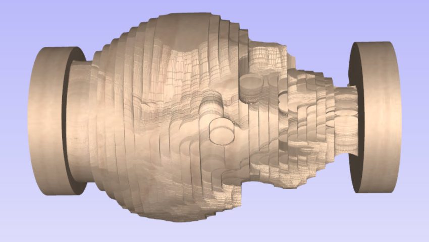
Once the roughing pass is complete, run a finishing pass just like we did in Your First Project. Here you can see a preview of the roughing pass, and then the finishing pass.
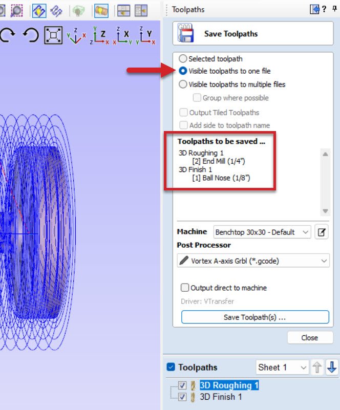
Save and export your g-code for your roughing and finishing toolpaths with the new post processor just like we did in Your First Project.
Preflight Checklist
What we’ve done so far:
- Measured and Prepped your material (we will do even more prep)
- Exported 2 g-code files w Vortex post processors
- Align the Y axis
- Enter Rotary Mode
- Have the Correct Bit in place
- Set the X & Z axis
Before we take off:
- Examine Workholding using the Tailstock and Faceplate
- Use the Stock Turning tool
- Explore Tool Changing options
Workholding
In Your First Project, because our stock diameter was 1”we used the chuck’s jaws to clamp the wood directly into the chuck. For this project, we will be using the screw-on workholding face plate, because we are using tabs. We will also be using the tailstock to add some support to our job.
Faceplate
The face plate can use four #4 – #6 sized screws that are not included. The center hole is great for centering the faceplate on your stock, but not necessary for running your job.
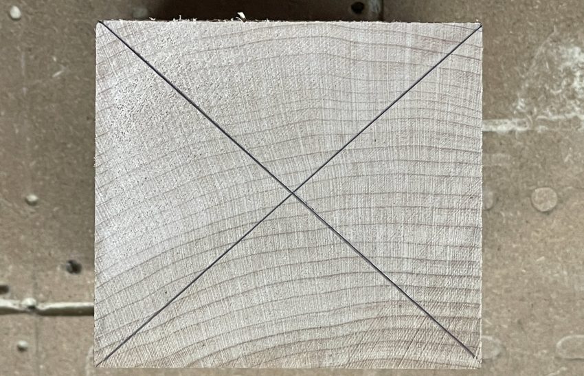
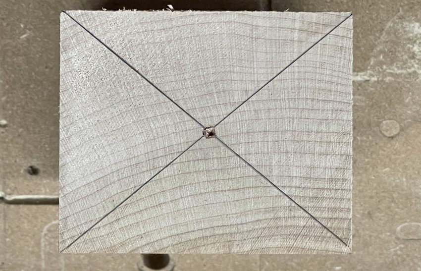
We want to find the middle of our stock, and mount the center screw as close to that as possible. To find the center, simply run a line from corner to corner. Where the lines cross is where we want to pre-drill a small hole to allow the screw to grab in the correct spot.
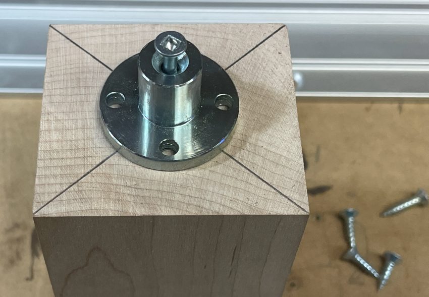
Once the center screw is in, you can continue by putting the 4 smaller screws around to secure the faceplate.
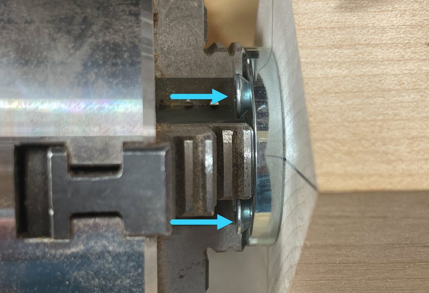
Once the faceplate is secured, place it into the chuck so that the screws are between the teeth, and tighten the jaws down.
Tailstock
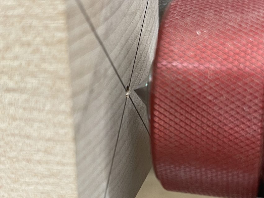
Once your stock is held firmly in the headstock, you can slide the tailstock towards the center, by keeping the red flange up. Check that the live center is flush against the tailstock, and not extended yet.
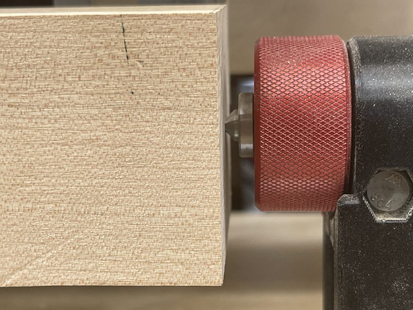
Ensure that the live center is aligned with the center punch and then push the red flange down to lock the tailstock in place.
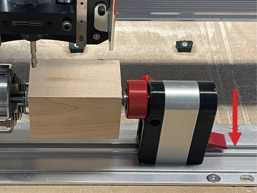
Now you can spin the tailstock live center away from you to tighten it down. Once the pin has made solid contact with the project, you can secure the red knob on the back. Just finger tight is fine here.
Congrats! Your material is in place, let’s turn it into stock we can use for our roughing pass now.
Rotary Surfacing
Now it’s time to turn that square stock down to a cylinder and reduce the strain on our end mill for the roughing pass. We will be using a ¼ inch upcut end mill for turning stock, as it’s the most efficient. Fire up gSender and focus on the Rotary tab.
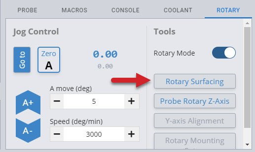
You will need to be in Rotary Mode to use the stock turning wizard.
Rotary surfacing is similar to the regular XYZ surfacing wizard. Let’s explore this a bit further.
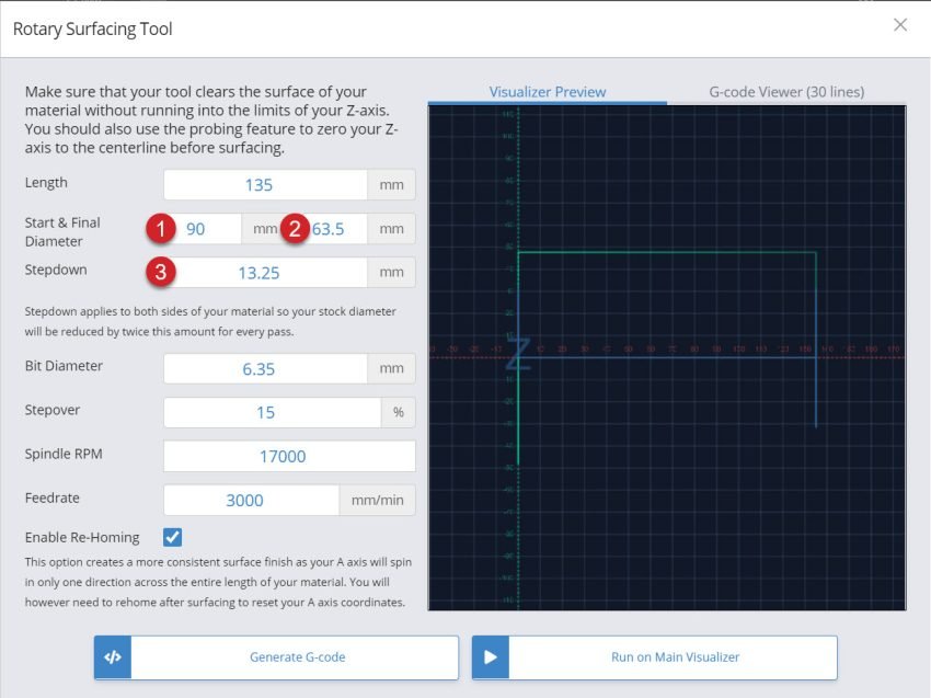
- Your start height is the largest diameter on your stock. Usually this means the diagonal distance from opposite corners if you’re starting with square or rectangular stock.
- Your final height is determined by the short side of your stock, although it can be even smaller if needed.
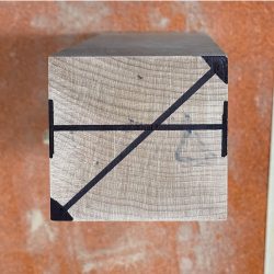
- With a starting height of 90mm and a finished height of 63.5mm, we are removing 26.5mm of material. However, since we have the Z axis set at the center of the material, we will need to divide that 26.5mm in half. We are basically taking 13.25mm off of the top and the bottom.If you want a single pass, your stepdown would be 13.25mm. Dividing that by two and setting the stepdown to 6.625mm, means that we will be doing two passes. This will produce a piece of round stock with the maximum diameter possible.
(Start Height – Finishing Height) / 2 = Total Stepdown for ONE pass
Congrats! You have prepped your stock for its roughing pass. Since we are using the same ¼” endmill, you can simply load up your roughing g-code and hit start.
Tool Changing
Since we’ve got two separate toolpaths, with two separate cutting tools used for roughing and finishing, we’ll have to decide on how we’ll be changing out these tools. This is no different than any regular tool changing you might do with a regular XYZ CNC project, we can either:
- Use two separate files exported with each tool in its own file, then load and run each of these files on its own.
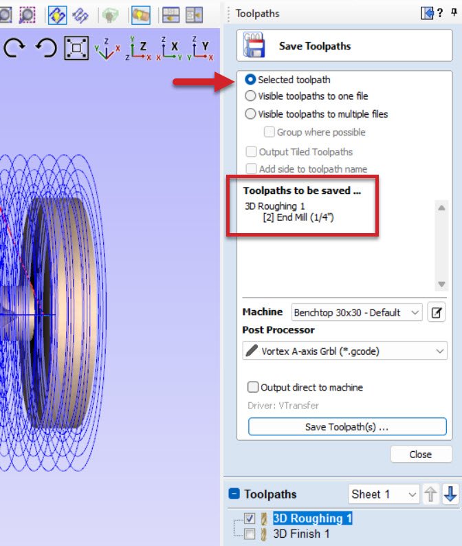
- Use one single file which contains an M6 command to prompt a tool change. When the time comes to change tools, gSender will pause the program to allow you to change the cutting tool, probe the new tool, then resume again once ready. More information on how gSender can help you perform tool changes can be found within the gSender Resources.
Which of these two options you’d like to use likely depends on your personal preference and experience between the two, but either will work the same.
During the tool change, one thing to be very mindful of is to not bump into the Vortex chuck or mounted stock. Similar to how you’d want to make sure the X or Y axis doesn’t move when changing tools, you’ll want to pay special attention to not rotate the A-axis.
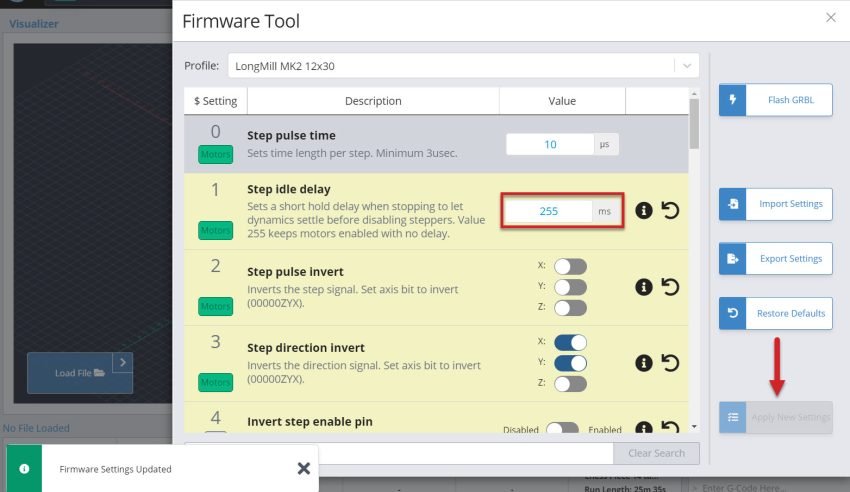
One way to do this is to enable holding current in your firmware settings. Simply navigate to your Firmware tab and ensure that you have $1 set for 255. This will keep the A-axis stiff and prevent you from bumping it out of alignment. If you’re unsure of this setting and what it does, leave this unchanged as it could cause more issues than good.
This possibility of losing the A-axis position is one of the main reasons for using the A-axis limit switch to allow for homing this axis along with the others. If this gets thrown off by accident and you’ve already homed the machine before starting, you can simply run the homing cycle again and get everything repositioned exactly as before.
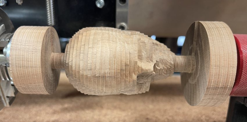
Roughing Pass
After you’ve switched the tool, you’ll simply re-zero the new bit onto the top of the Vortex chuck the same way you’ve done before.
Now you can load up your finishing pass g-code and hit the start button to run your final pass.
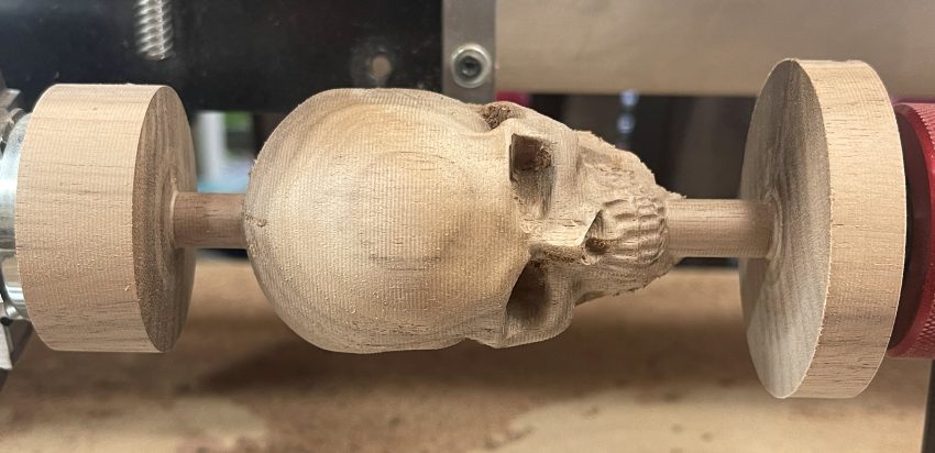
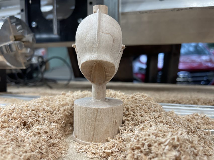
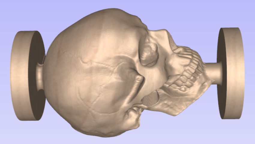
Finishing Pass
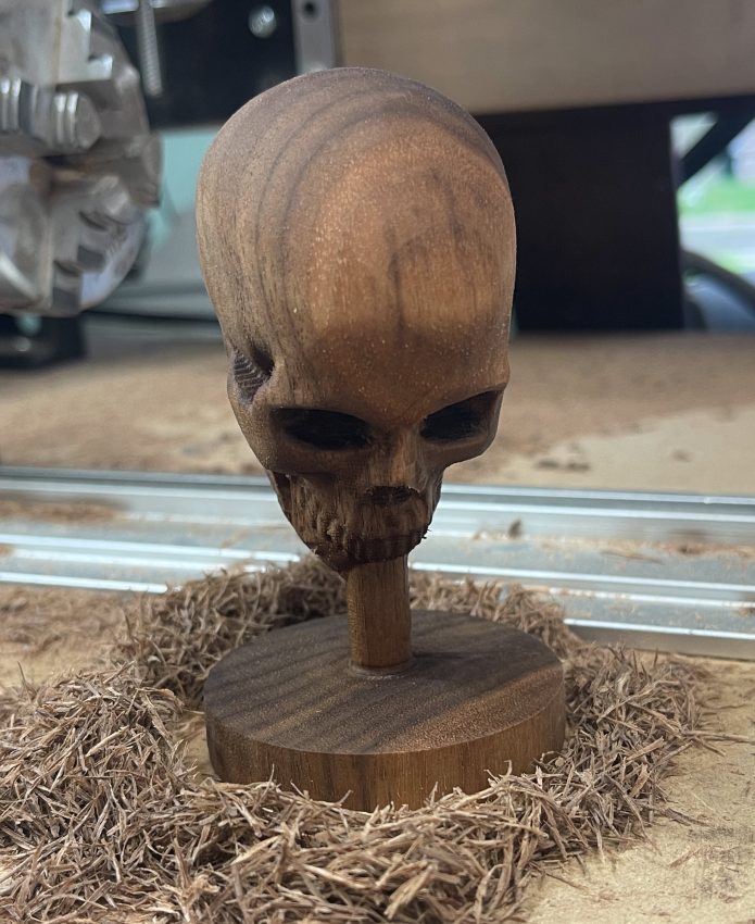
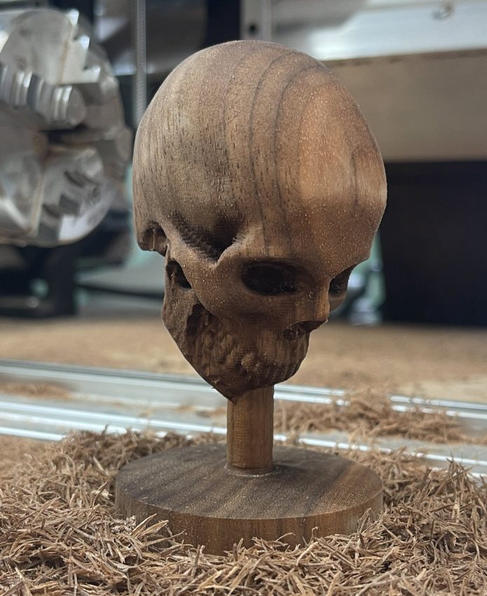
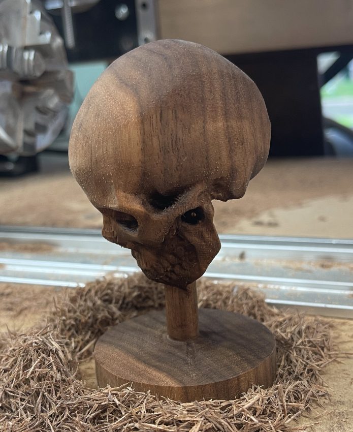
Congratulations! You now have a Spooky Skull. Back off the tailstock and remove the faceplate from the chuck and admire your second project success.
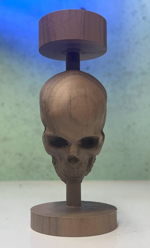
Finally we cut off the top tab and sand with 220 grit. Mission accomplished! You now have that skull on a stick that you’ve always wanted. 🤩