
The process of creating toolpaths for the Vortex rotary axis is largely similar to that for any benchtop CNC, so if you’ve made a toolpath before, you should feel right at home with this new workflow.
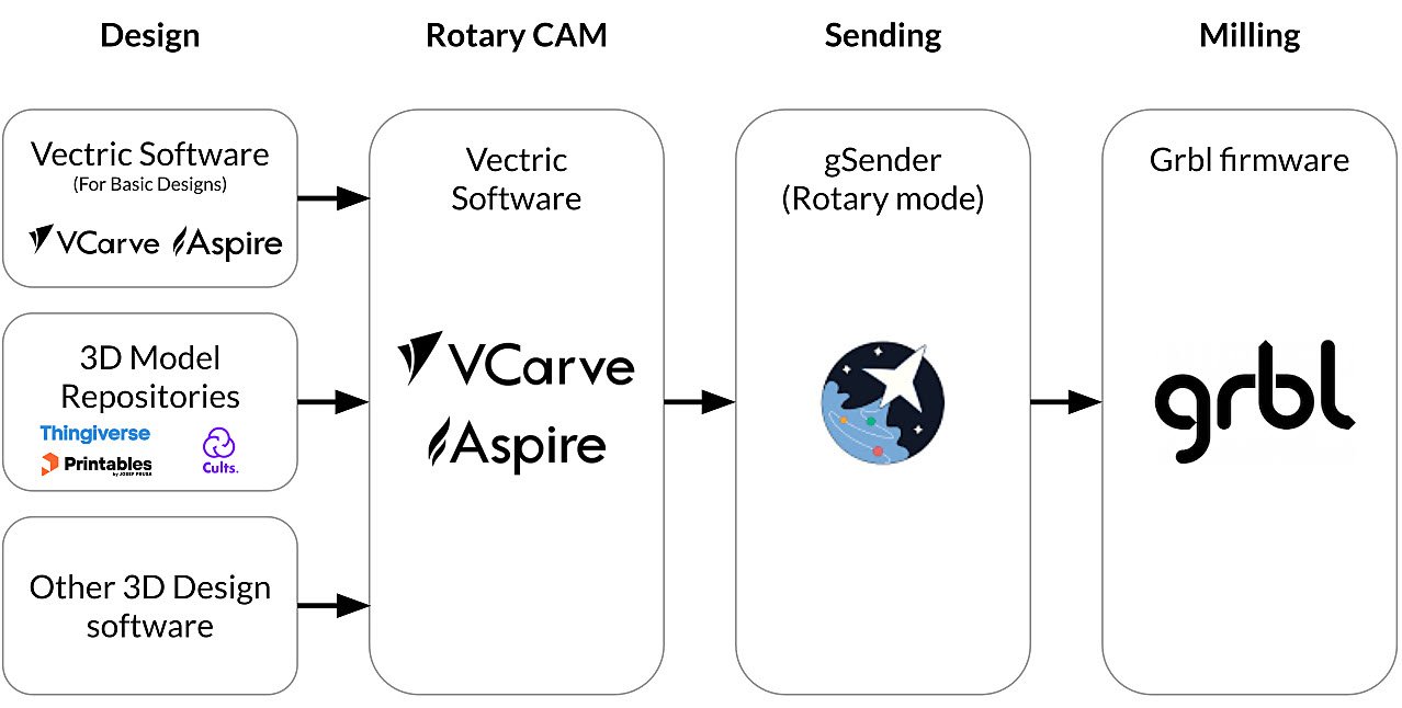
We highly recommend that you use software by Vectric (VCarve Desktop / VCarve Pro / Aspire) since it offers best-in-class support for rotary and is relatively inexpensive. For the purposes of this article we will focus on how to create rotary toolpaths in VCarve.
We also recommend that you use gSender as your sending software since it offers native support for the Vortex rotary axis (almost as if we built it ourselves 😃) alongside a host of other features to make your rotary experience as seamless as possible.
Create Toolpaths with VCarve
The basics of using VCarve is extensively covered by Vectric’s official training videos alongside other online resources. We especially recommend that you gain some experience importing 3D models and creating 3D toolpaths in VCarve before moving onto rotary carvings as the skills gained there are highly transferable. Having said that, we are going to assume that you know the basics of using VCarve and we are only going to highlight what makes rotary toolpathing tick in this section.
The Concept of Wrapping
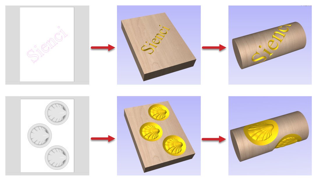
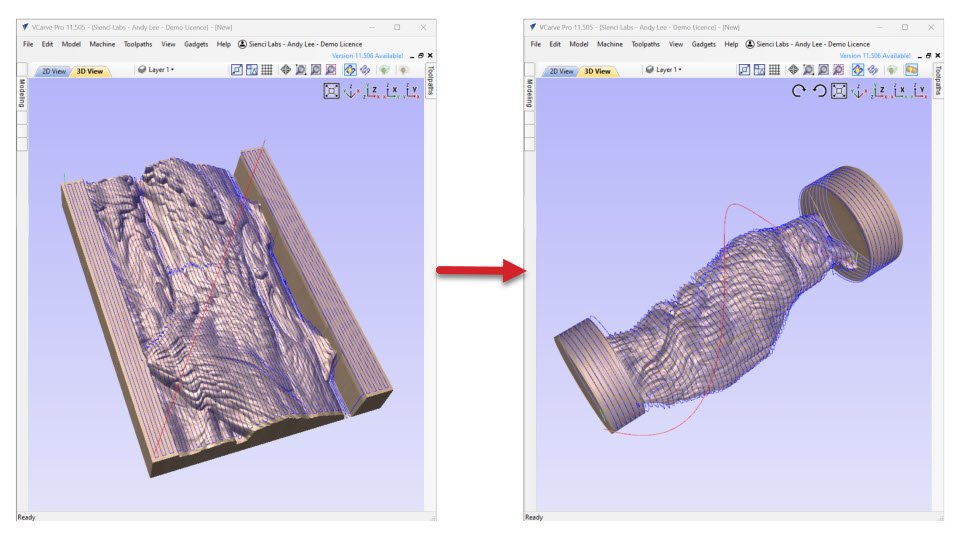
To begin with, it is important for you to understand rotary carvings as single-sided carvings that are wrapped around a cylinder. You still lay out your designs in 2D, but those designs are then wrapped around a cylinder when it is being previewed or carved. If you have ever carved letters or reliefs into a piece of flat material, you can imagine rolling the end results up into a cylinder and you’ve essentially got the gist of rotary carving in VCarve.
Job Setup

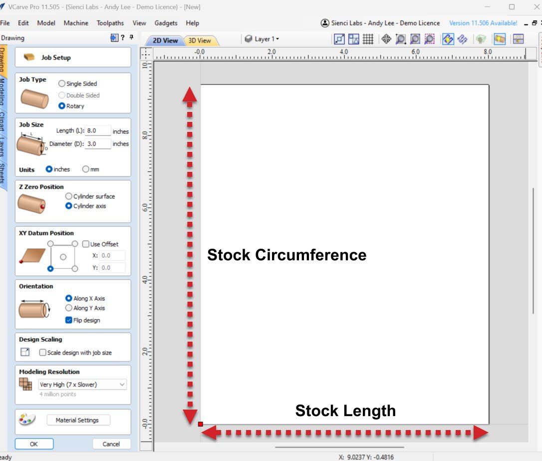
When you start your project, there are a few Vortex specific settings that you should pay attention to in the Job Setup panel. In particular:
- Job Type – Simply select the “Rotary” option. You will see it changes the options below once a bit once selected.
- Z Zero Position – You should set the Z-axis zero position for your job to “Cylinder axis“. This helps the visualizer display toolpaths correctly and makes zeroing easier as you will have a more consistent touch off point to work with even after you have performed a roughing pass. If you try to set the Z-axis zero position to your work surface and do a roughing pass, you no longer have a reference point, since the material has been roughed away.
- Orientation – You should set your job orientation to “Along X Axis” as this is the default orientation for the Vortex.
Your 2D view will now represent the outer surface of your material, where the height of the workspace corresponds to the circumference of your material, and the width of the workspace corresponds to the length of your material.
Designs in 2D
We will go over how 3D models work in VCarve in the next subsection, but we’d like to note here that you can still create some amazingly intricate designs (Such as embossing details onto a rolling pin) without using a 3D model. This is possible as you retain access to all conventional drawing tools, including the options to bring in vector files and images in rotary mode, with which you can create V-carvings, pockets and more like you would on a piece of flat material. Just remember that your designs are ultimately going to be wrapped around your stock cylinder.

Designs in 3D
See our page on “Finding 3D models” for more information about where you can find 3D models to carve.
As mentioned in the “The Concept of Wrapping” section above, VCarve operates by wrapping a flat design around a cylinder to create a rotary design. This means that even when you are importing a 3D model, VCarve will first need to “unwrap” the 3D model into a 2D image, with this representation then re-wrapped around a cylinder to form the final shape. This workflow may seem counterintuitive at first, but has major benefits for when you create toolpaths in the next step.
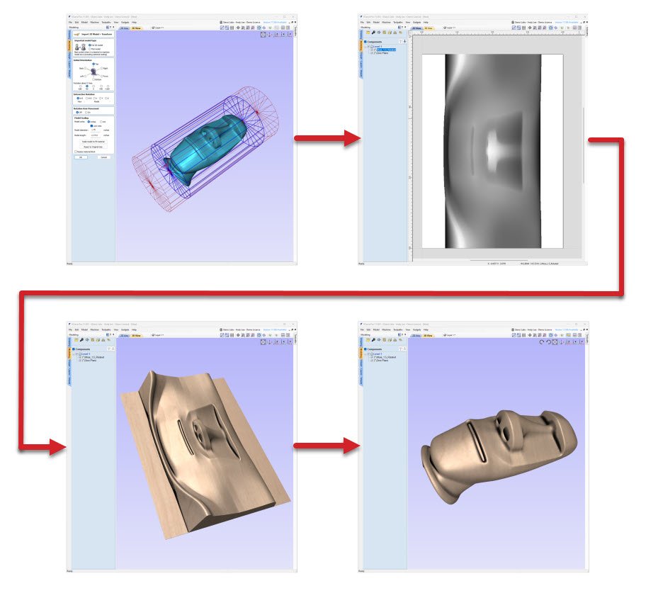
The exact procedures to import a 3D model should feel largely familiar if you have imported any models to VCarve in the past, and you can brush up on those procedures with Vectric’s own training materials including orientation, rotation and scaling. The main difference lies with the new positioning and scaling controls which may take some getting used to.
Once your 3D model is imported, it is also a good idea to add some supporting geometry to the two ends of your model so it stays connected for the duration of the carve.

Creating Toolpaths
Once you are happy with your design, you can move on to creating toolpaths for carving. Since we are dealing with an unwrapped cylinder in 2D, all of the usual carving options are available at our disposal such as 2D contouring & V-Carving, or 3D roughing & finishing. The resulting toolpaths will again simply be wrapped around a cylinder to create the final desired cuts.
To improve surface finish, we recommend that you use the “Raster” strategy with a 90 or 270 degree raster angle when creating your finishing toolpaths. This setting lines toolpaths up so that they always cut across the surface of the cylinder and results in less pronounced seams.

Lastly, a note on feed rate since it is interpreted differently on the rotary axis. You should not be surprised that actual carving speed is slower than what is specified. Our recommendation is for you to start with using our MK2 Feeds and Speeds library and make adjustments on the fly with the feed rate override in gSender.
Exporting Toolpaths
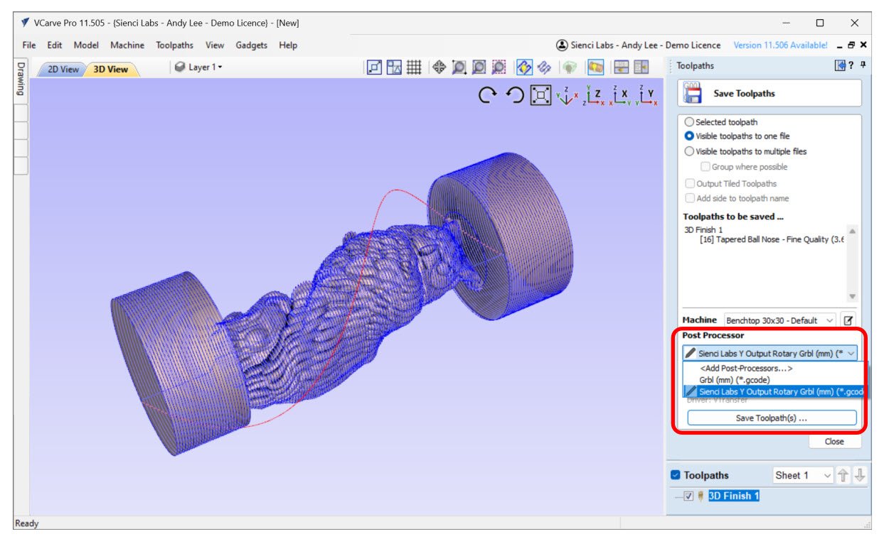
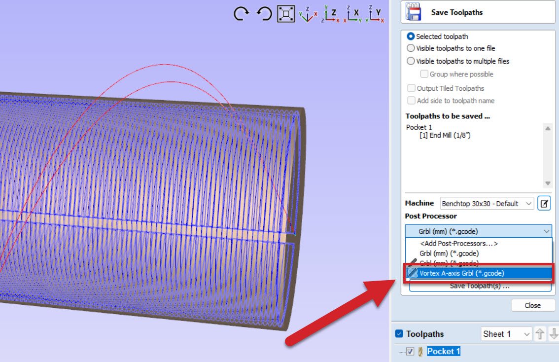
To export your toolpaths into a g-code file, you will need to import and use a new post processor that we created for the Vortex. The new processor allows you to use A-axis commands and even allows for tool changes using the M6 command. You can download it with the link below. Note: This post-processor is for Vectric Software only.
Post Processor Installation
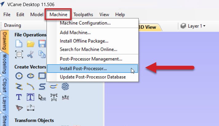
To install these post processors in VCarve Desktop, select Install Post-Processor under the Machine tab.
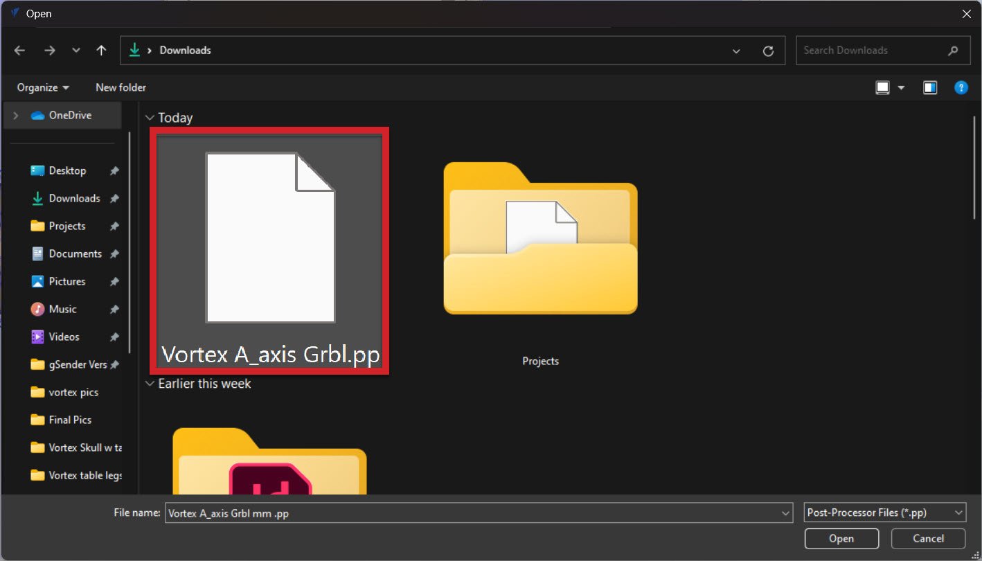
Select the Vortex A-axis Grbl.pp file from your recent download.
Now when you go to save your toolpath, you will be able to select the correct post processor for your rotary project!
Cue gSender
Once you have your g-code file at hand, you will want to bring the exported g-code over to gSender where you will be able to visualize the toolpath you just created.

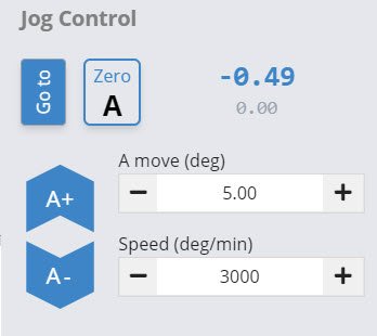
A “rotary” mode is also built into gSender, where you will find jog controls for the rotary axis along with options for probing and zeroing the X, Z, and A-axes. When rotary mode is enabled within gSender, this will allow for movements on your A-axis/rotary axis that are up to 8000 mm/min, allowing reasonable feed rates when cutting small diameter stock. You can see that switching the rotary slider sets $111 to 8000 in the firmware tab.
The pages on “Unboxing” and “Your First Project” will better fill the gaps on setting up your Vortex, mounting the material, and establishing a starting point. Assuming all that is already done, that last step should just be to hit “Start” and watch as your design materializes in front of your eyes!

