
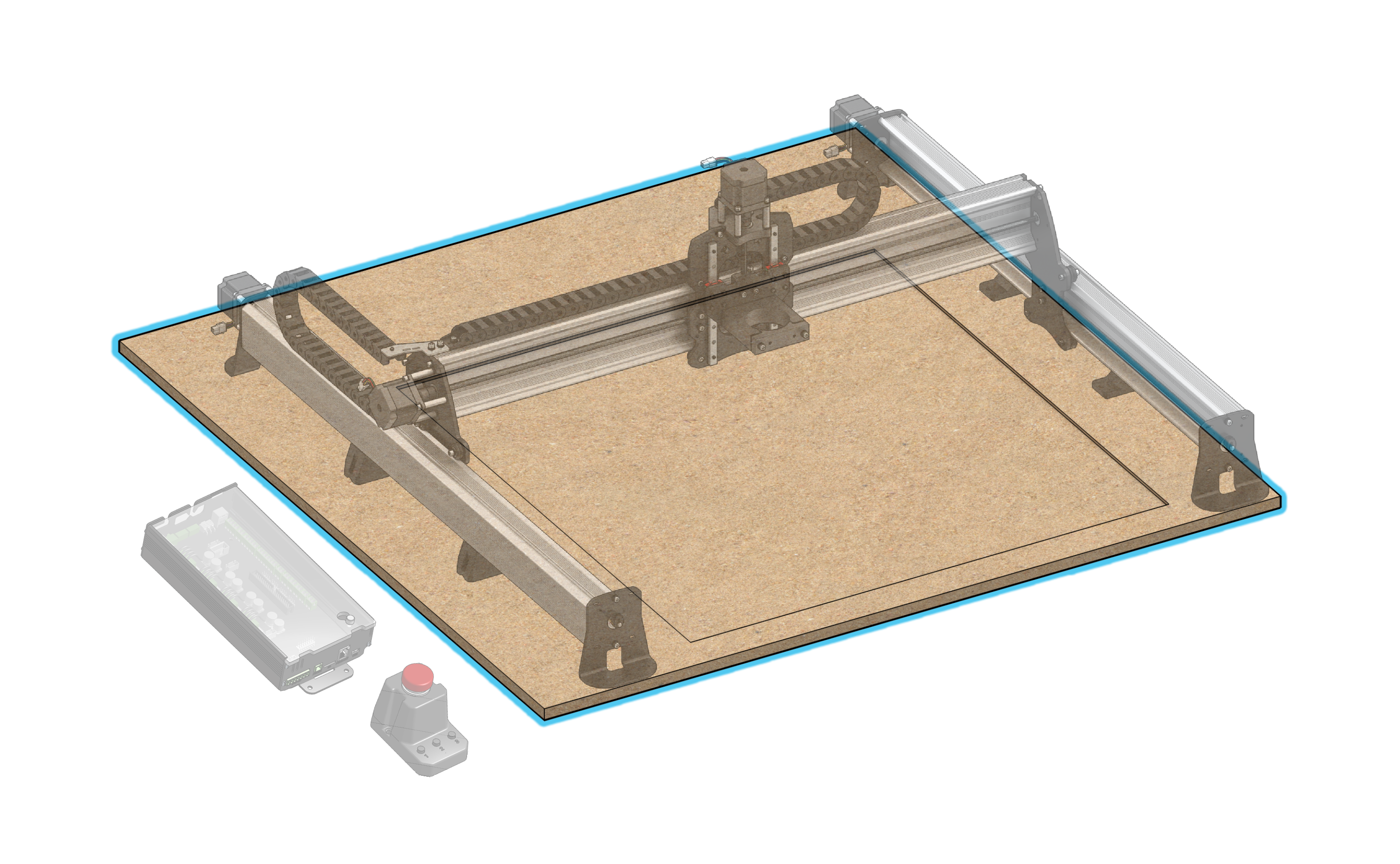
The LongMill is designed to be mounted to a flat surface which is provided by the user. This could be as simple as a single sheet of material, or as intricate as a multi-piece torsion table with t-tracks and threaded inserts. This helps to:
- Save on the cost of shipping. For example, a 4’x4′ piece of 3/4″ MDF shipped often costs over a hundred dollars in shipping and is very easy to damage during transit. Instead, you can usually find a full 4’x8′ sheet of 3/4″ MDF for under $60 at your local lumber or hardware store.
- Give users flexibility to choose the size and material of the wasteboard to match their needs.
Suitable Wasteboard & Table
There are two factors to consider for your setup:
- The table / mounting surface itself: this needs to be relatively flat to properly mount the machine to and it should be relatively sturdy as well
- The wasteboard: this is the cutting area of the machine that you place material within and will get worn out over time. This will get flattened and occasionally re-flattened by your LongMill to ensure any material you cut is parallel to the machine. Ideally this should be removable. If you want to pass larger material through the cutting area you should also ensure the wasteboard is the same size as the machines cutting area otherwise it’ll leave a lip when you flatten it out
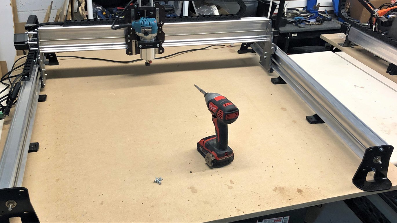
The easiest setup that we recommend is a flat, clean piece of 3/4″ MDF to act as both your mounting surface and your wasteboard, as shown at the start of this section. This is because 3/4″ MDF is quite stiff and is readily accessible in 4’x4′ and 4’x8′ sizes from most big-box hardware stores or a lumber store. Any similar piece of thick, flat material would also suffice.
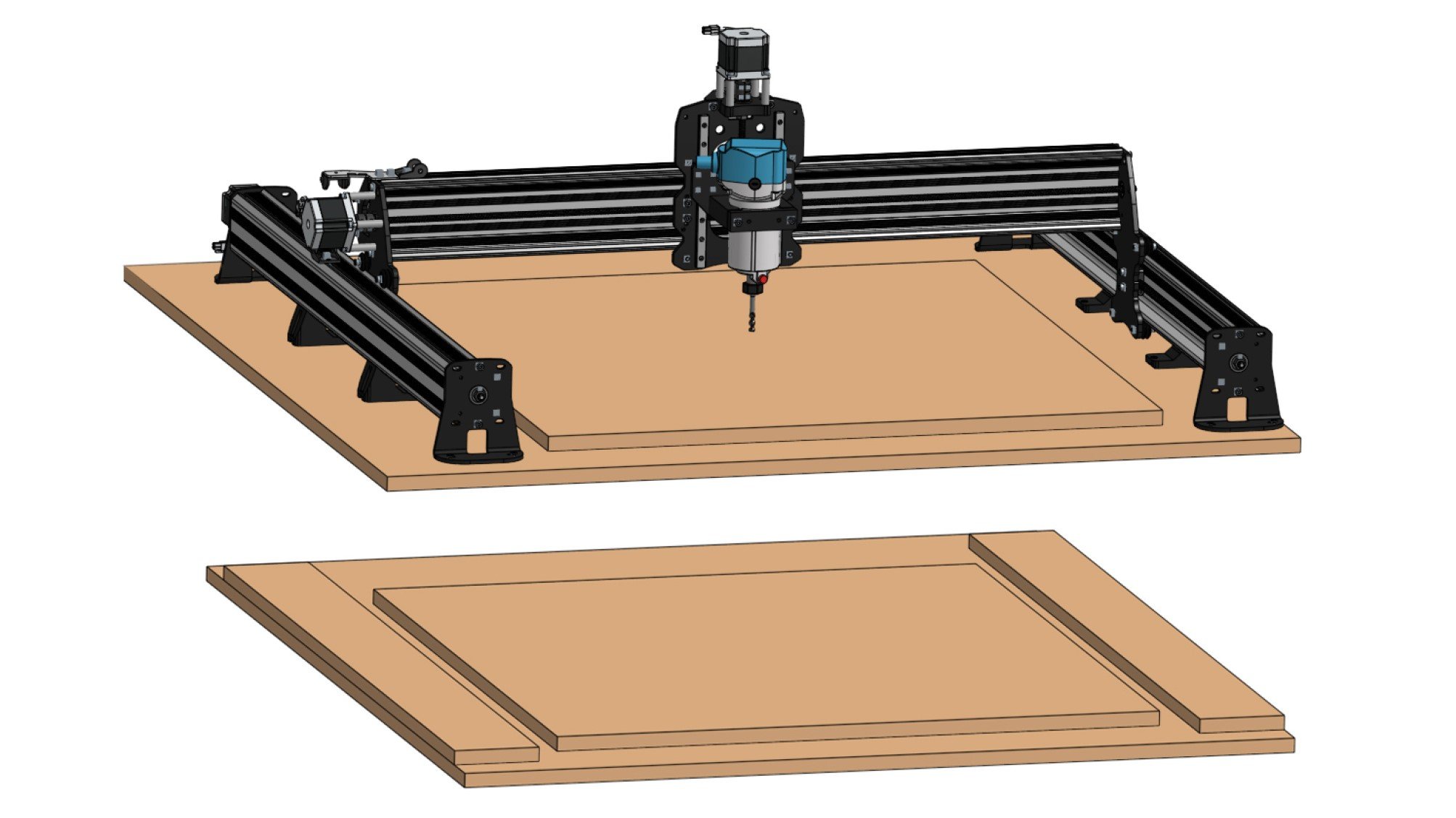
A higher-quality setup will have both a flat surface that your machine mounts to as well as a removable surface that you can cut away at to ‘re-flatten’ after it starts to show some wear. You can see some examples of this above, one with a spare piece of MDF as the wasteboard and another with added ‘foot risers’ to maintain the LongMill’s tall cutting height. These sorts of setups can sometimes be made out of a single sheet of 4’x8′ MDF as shown below. Feel free to see more inspirational example setups by our community members here: https://resources.sienci.com/view/lmk2-table-enclosure/
Machine Dimensions
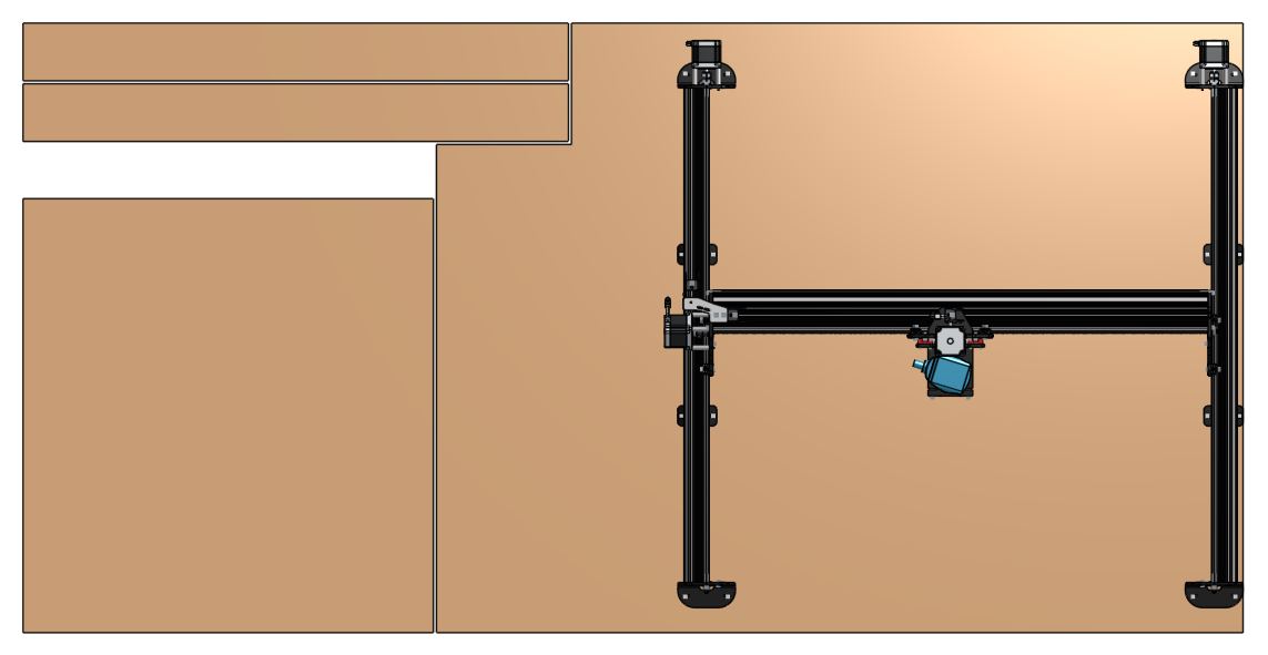
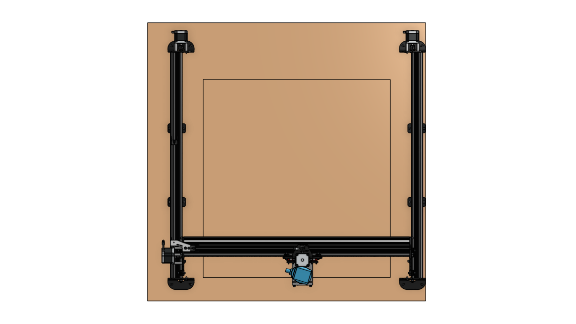
When getting ready to mount your LongMill the mounting surface will need to be at least the same size or larger than the space the feet take up, known as the ‘foot base’. In addition, some parts of the machine extend outside the foot base like the stepper motors, so leave enough space around your mounting surface to account for this ‘total machine outline’.
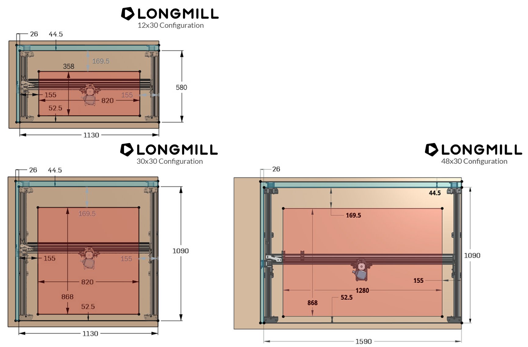
Each MK2.5 model (12×30, 30×30 and 48×30) is designed to generally fit on a 2’×4′, 4’×4′ and 4’x6′ surface respectively. The diagrams above show a more detailed view for each model where the red represents the travel / cutting area and the blue shows the hanging features outside the foot base.
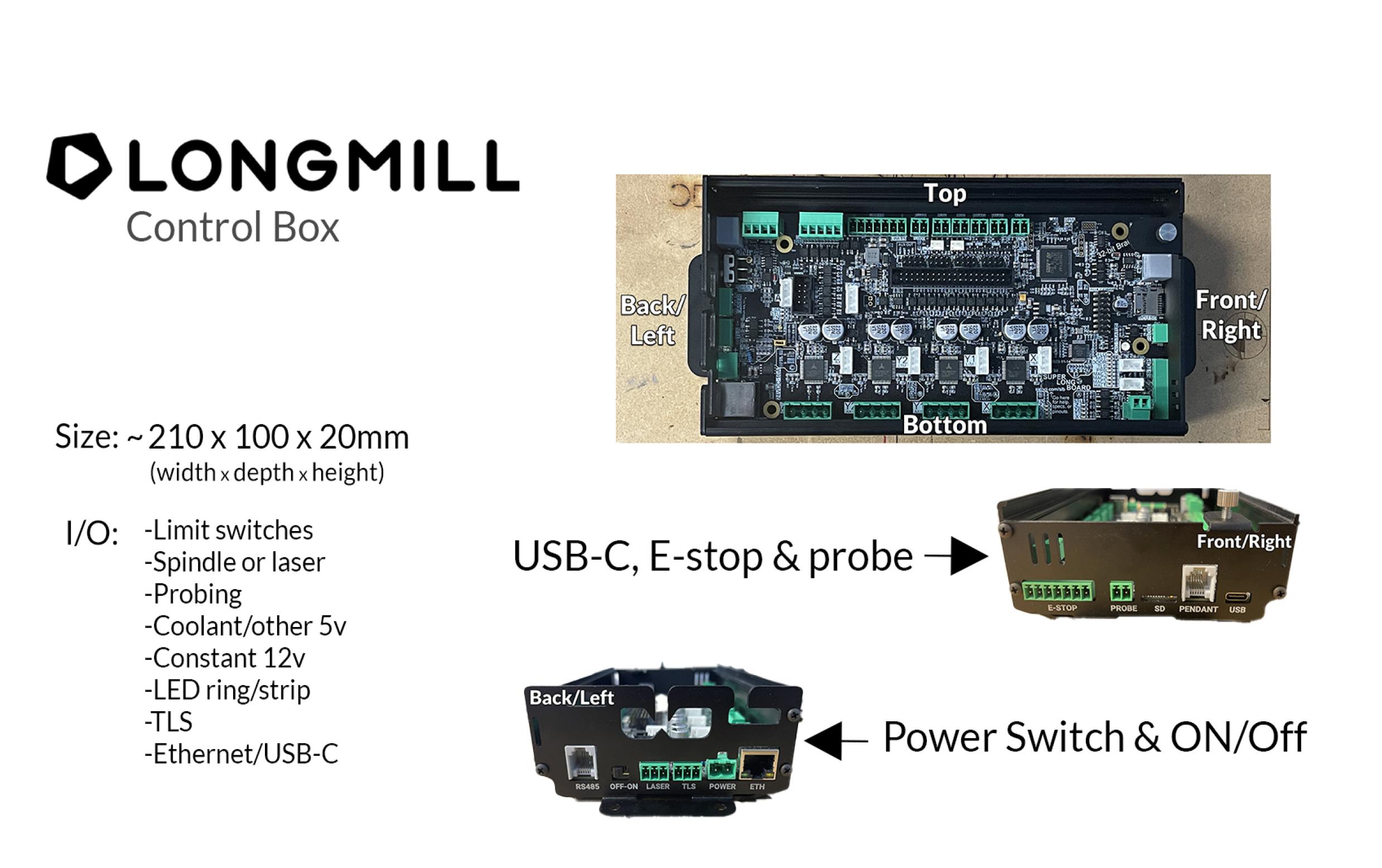
The control box is also something you should plan for. It has the USB, E-stop and probe connections on the front side of the board, whereas the majority of cables come through the cable organization holes in the back of the board. When mounting the case, be aware of the length of your probe and E-stop cables and position them within easy reach.
Power is fed in through the back of the board, along with a power switch you can use to turn the board on/off. Normally the control box will plug in on the left side of the machine (unless you mirrored assembly to put it on the right side) and you can have it screwed into the table or fastened to the rail. (MK2 only)
Mounting your LongMill
There’s a simple step-by-step process you can follow to ensure that your machine is mounted securely and accurately. Ensure your computer is connected to your machine so that you can move it around between steps. You can use the wood screws provided (#8 x 1″), or use your own mounting hardware depending on your setup. Either way, a drill with a long Robertson driver or a bit extender works best to reach all the holes when you begin screwing the feet into place.
Gently place your LongMill on the mounting surface roughly where you want it. Usually you’ll want to have a reference ‘straight edge’ on the right and front of your surface to align the machine to; whatever best suits your setup. In this case we’re using a 4’x4′ MDF sheet as a combination mounting surface and wasteboard which we had cut to 42 inches to better fit in a car. We’ll be mounting it in the middle offset from the factory edges and have the electronics box sit off to the side.
Start by moving the machine all the way to the front by jogging in the Y-axis on your control software. Keep moving forward until you hear a grinding coming from the motors on both sides to confirm that your machine is all the way forward on both sides. After this you can jog backward slightly.
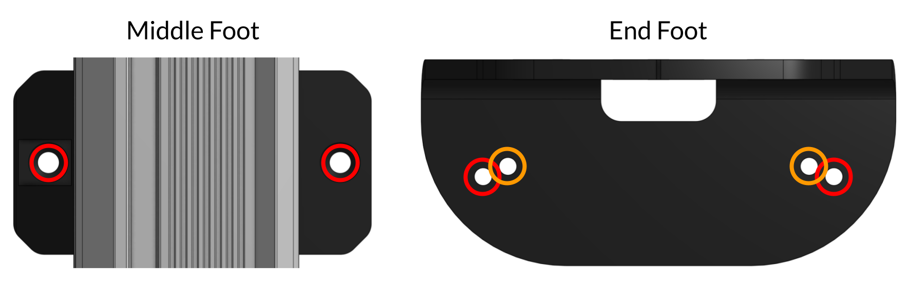
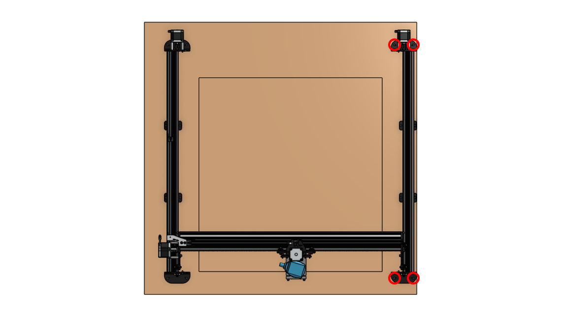
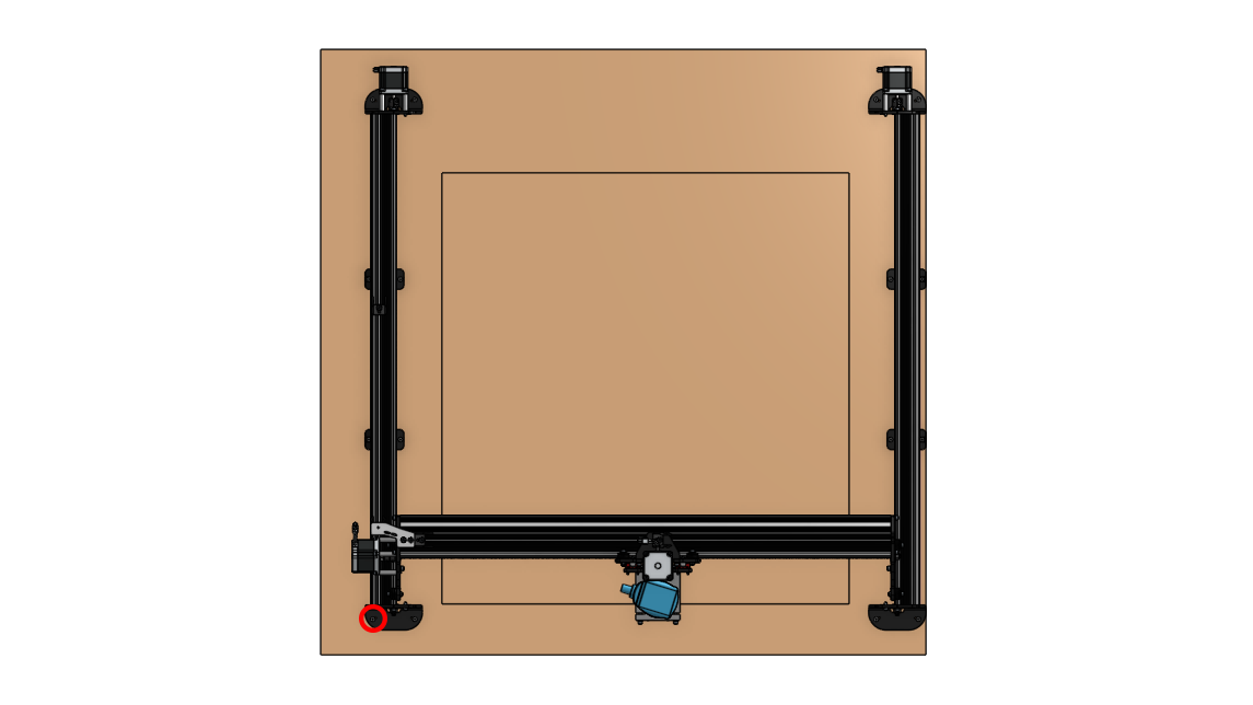
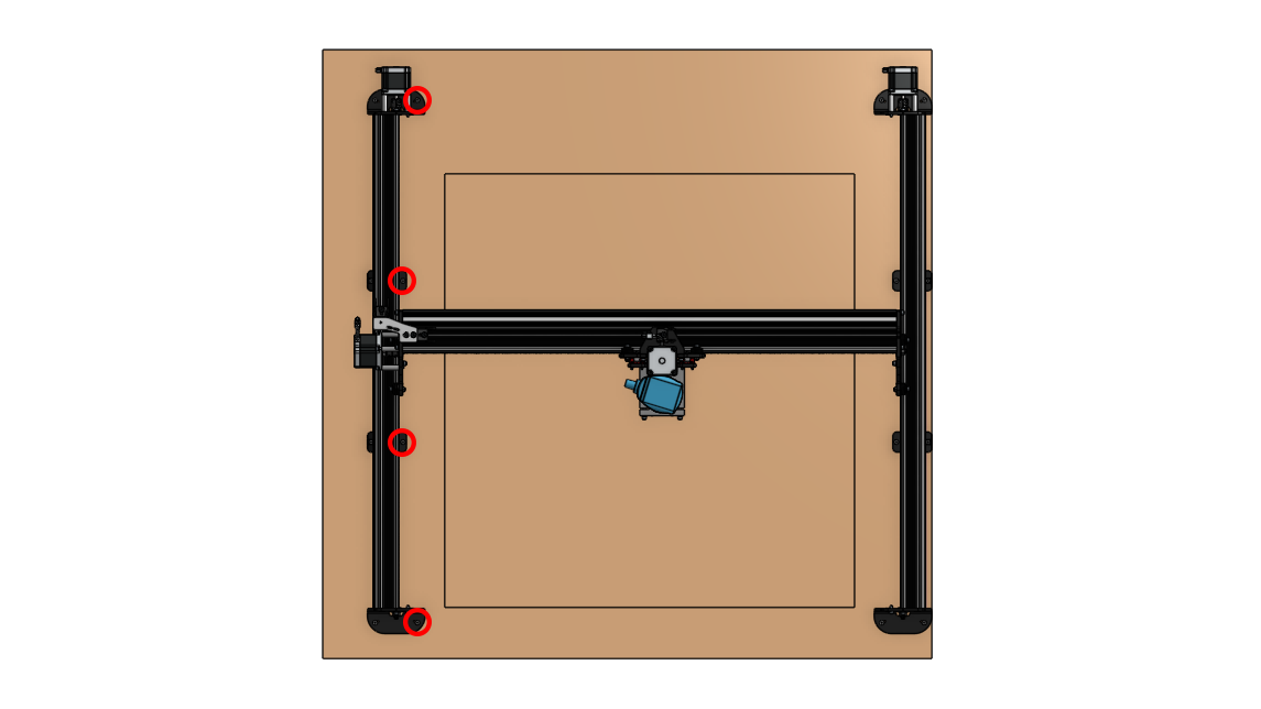
First we’ll be mounting the whole right-side of the machine into place. Each foot has two primary holes for mounting (red circles) and the steel end feet have a backup set (orange circles) built-in to allow you to make adjustments in case you find that you made a mistake later on.
Start with the steel end feet using 2 screws per foot and ensuring they’re aligned to where you want your machine to be. If you’d like to pre-drill the holes to avoid shifting around that’s an option as well.
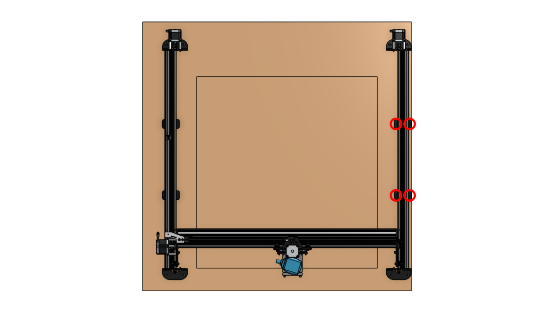
Next screw in the middle feet on the right side. Don’t ream down as hard on the plastic feet as you did on the steel ones.
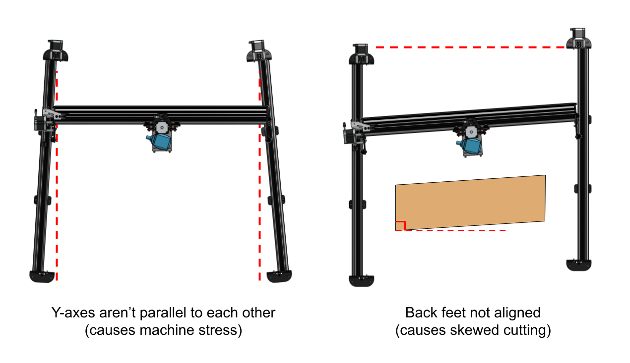
At this point the right side of your machine will be fully secure. When mounting the left side, we’ll want to ensure it’s mounted parallel to the right side and also that the back feet are aligned to each other. You can see in the diagram below why mounting the rails both parallel and in-line is important to ensure the CNC isn’t overly stressed and also cuts how you expect it to.
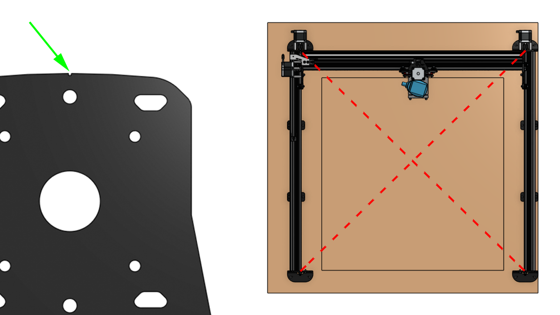
Checking for ‘squareness’ can happen many different ways depending on your tools at hand. For example, if your right side was attached 90° to your table front, then make another 90° mark for the left side to reference using a straight edge and a carpenter’s square. If you have a friend to help you, the steel end feet also have a small notch built-in that can allow you to run a measuring tape under the X-rail from the top left to bottom right foot and top right to bottom left foot. Adjust the left side until these two measurements are equal and that’ll ensure your machine is mounted square.
A third option is to use the ‘XY Squaring’ tool that’s built into gSender. This tool is probably too fancy for most people but it’s one of the most accurate ways to check the squaring on your machine. You can read how to use it here if you’re interested and then come back to continue assembling once you’re done: https://resources.sienci.com/view/gs-additional-features/#xy-squaring
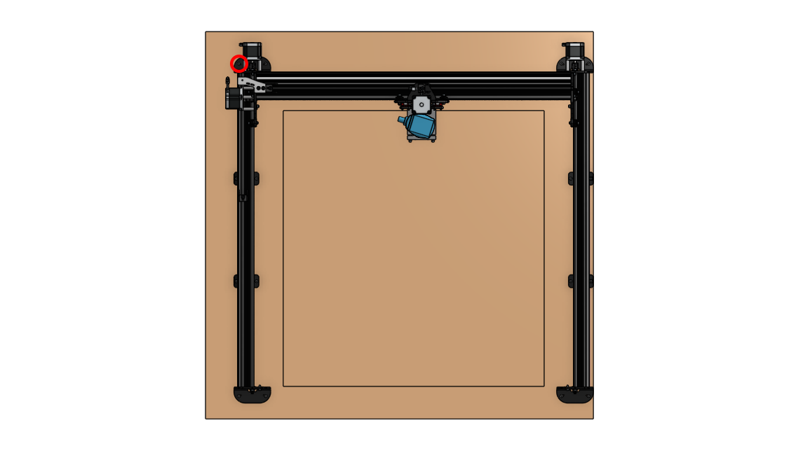
Once you feel confident in the foot placement, drive the first screw into place on the front left foot:
Then jog your machine to the rear and drive in another screw on the back left foot:
Now double-check that everything is looking correctly aligned before completing the mounting. At this point if there seems to be an issue don’t sweat it, the second set of holes on the steel end feet will allow you to make small changes in how the machine is mounted. Once you’re happy, jog the CNC roughly to the middle and finish securing the remaining foot holes:

Followed by the second screw for each foot. Once complete, Congrats! Your machine should now be fully secure and square to its mounting surface.
Mounting the Control box
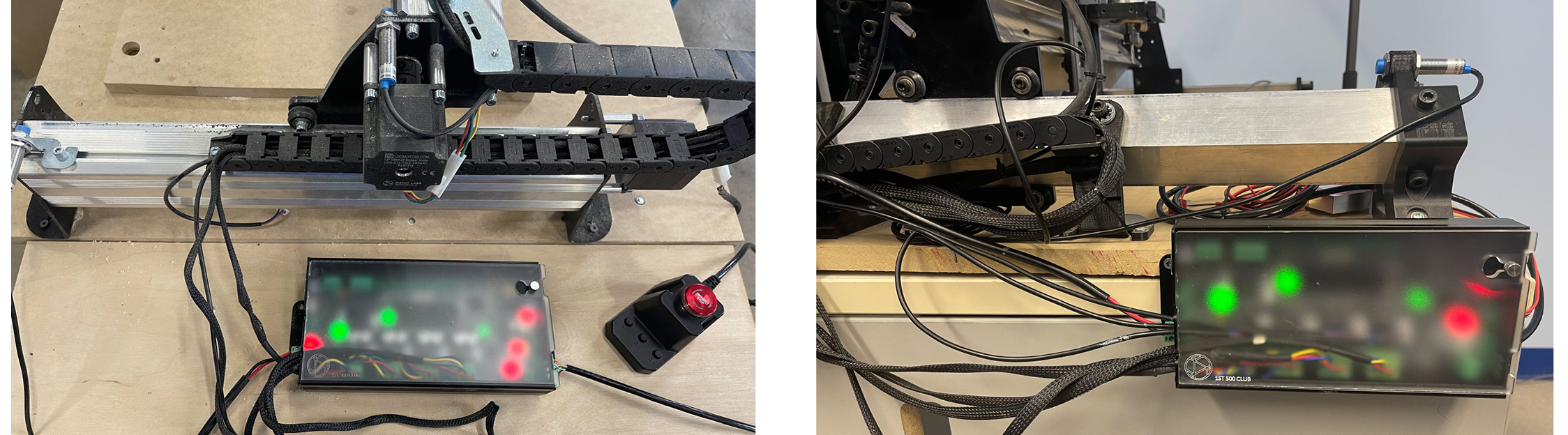
You can mount your SLB however you like. Some factors to consider might be your machine setup, computer location, if you have an enclosure, or if you want to access other things or see the pretty lights on the board. The most versatile way is the 4 holes in the SLBs enclosure which will allow you to mount it to any flat surface, but we recommend that you mount it directly to your Y-axis rail. You will find your bracket and hardware in the SLB box. Some of the extra tools you may need for this step:
- Bolting to MK2.5 Rail – M5 Allen wrench, bracket, 2 T-nuts and 2 M5 10mm bolts
- Screw Down / Flat Mounting – 2 to 4 wood screws (minimum size #4 or ¾” and min length of ½”) plus the necessary screwdriver or bit driver
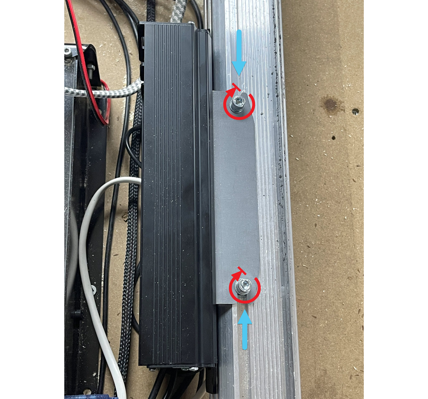
For rail mounting, slide the two T-nuts onto the track above the left Y-rail and loosely thread on the two M5 bolts.
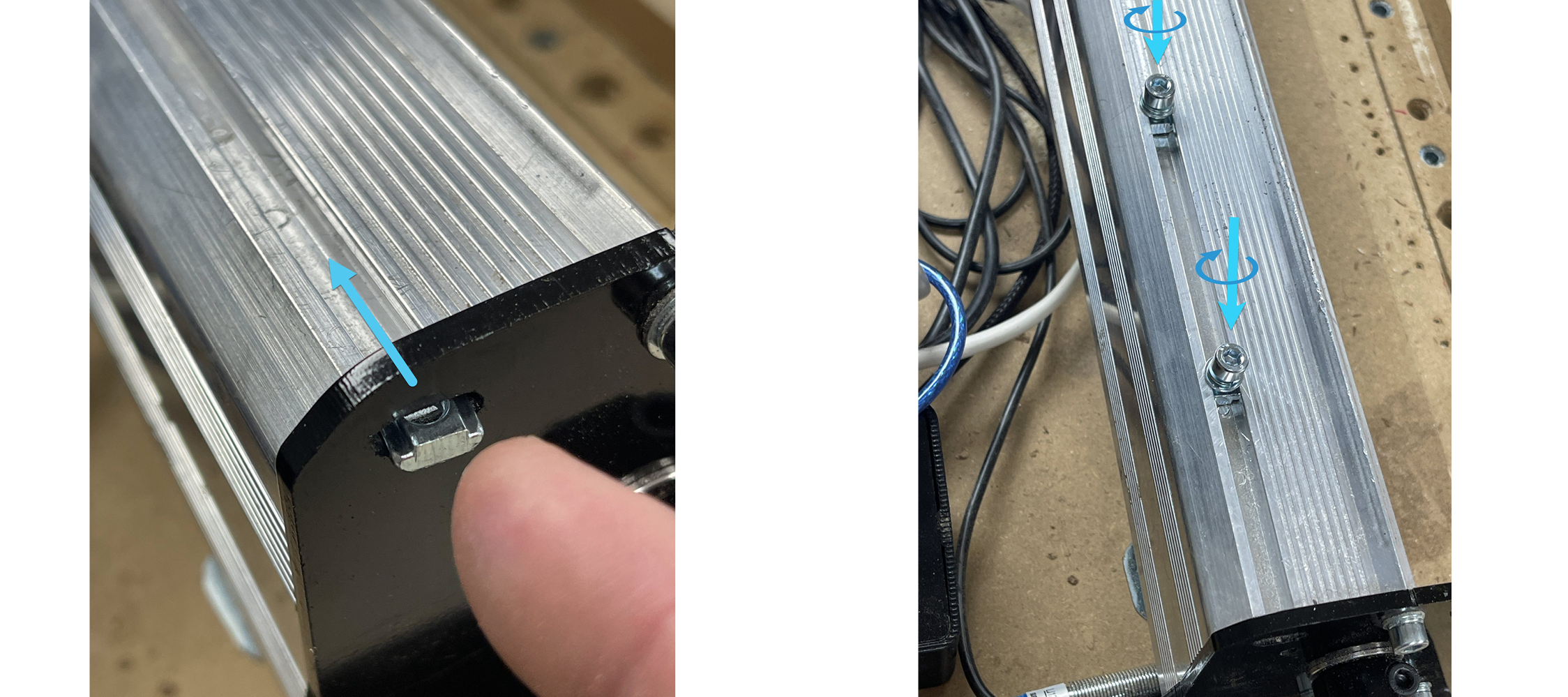
Insert the sheet metal bracket into the slot at the back of the SLB enclosure. The bracket will feel loose for now so you’ll want to hold it in place until the next step.
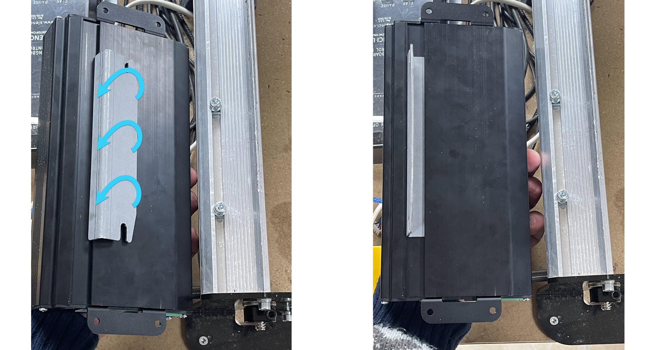
Place the bracket-enclosure assembly onto the Y-rail and slide the two screws into the slots in the bracket, then tighten the two screws with an Allen key to lock the entire assembly onto the rail.
You can mount your SLB flat on your wasteboard next to your machine, or even on the side or at the back of your workstation. You can also hang the SLB vertically. The enclosure has been designed with reasonable consideration for dust penetration and vibration, but if you are a more cautious person you can feel free to mount the box further away from your CNC.
When placing your SLB on its own or among other CNC control electronics, consider that most wires are designed to route out the backside of the enclosure with the exception of a handful of more typically accessible plugs on its front like the E-stop and USB.
It’s easy to use the enclosure as a template to mark and drill the holes. The holes are 4.5mm large, spaced 45mm from each other and 230mm from the opposite pair. They’re not perfectly centered on the box but close to it.
You can use whatever bolt or screw type you like but the easiest approach is to use a minimum of 2 countersunk wood screws on diagonal holes from size #4-#8 and a minimum length of ½”. You might have to remove some of the plugs on the ends to access the holes when you screw down the enclosure.
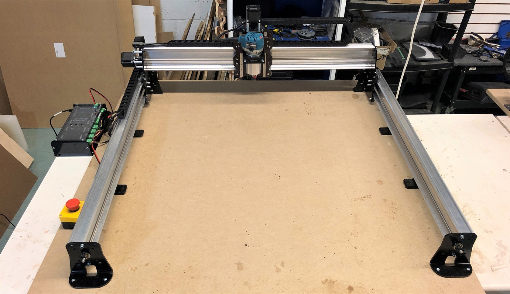
Mounting the Rest
With the machine mounted, take a once-over on the rest of your setup and see if there’s anything else you’d like to fasten down before you start on your first project:
- Power supply: The body of the power supply comes with 4 mount points. Screw it down out of the way and be mindful that it gets a little hot to the touch while it’s providing power to your machine.
- E-stop: the E-stop button is meant to be your ‘oops button’ so place it somewhere that will always be easy to access in an instant whenever something goes wrong. If you undo the 4 screws holding the E-stop body together you’ll see that there are holes to attach wood screws through the black bottom so you can mount it to any surface and reassemble the E-stop once you’re done. If you wish to place it further from the machine, extending it’s wires is quite straightforward by unscrewing the green connector and either using a soldering iron or a crimpable wire extender to lengthen it out.
- Motor cables: an easy way to tidy up motor cables is to drill holes with a spade or forstner bit right where the cables dangle down at both the rear Y-axis motors and where the remaining wires come out of the drag chain. This will allow you to run the wires on the underside of your workspace.
Steps Forward
You’re finished assembling your LongMill! Take a picture 📷 and pat yourself on the back for arriving here. People come from many backgrounds and pick up a LongMill so whether getting to this point took you an hour or a couple days we’re sure your LongMill will be very happy with the new home you’ve given it.
- The assembly manual concludes here but it’s not over. In the next section (which continues on in our online resources), we’ve got a walkthrough put together to teach you the basics on using your new CNC and cutting out your first projects! (https://resources.sienci.com/view/lmk2-first-project/)
- After completing this, we’ve also got a section on assembling any add-ons you might’ve purchased alongside your machine whether you’ve got the touch plate, dust shoe, t-tracks, limit switches, dust shields, laser, or others. (https://resources.sienci.com/view/lmk2-add-ons/)
- Finally with the first project out of the way and all the remaining assembly complete you’ll reach the LongMill Handbook. This section will become your bible on the LongMill, outlining all the daily operational details on how it runs, operation, feeds and speeds, maintenance, surfacing, project ideas and where to find them, troubleshooting, common CNC terms, and more. (https://resources.sienci.com/view/lmk2-handbook/)
You’ll see all these sections and more in our website resources for the MK2.5. Feel free to have a look around and also check out our sections on ‘CNC basics’ or ‘choosing software’ if you still feel like you could use more information on those topics.
We really hope you enjoy using your LongMill Benchtop CNC in the days, weeks, and months to come. Remember that CNC routers are an amazing tool that you can use for whatever you like, and the point of the LongMill and it’s community is to offer you resources and support so that you can be confident in using your CNC to make what you imagine. Good luck and happy making!
-The Sienci Labs team
Move on to the next page where you’ll get to carve out your first project ⭛