
This page accompanies the main LongMill MK2.5 manual, showing any assembly steps that are specific to the 48×30 version. If you’re installing a 48″ extension kit on an existing LongMill MK2.5, you’ll want to follow this page instead.

There will also be a link to bring you to the alternate steps and another link at the end of those steps to bring you back to the main manual.
If you’d like a printed copy of the entire assembly manual for the 48×30 LongMill, print the 48×30 MK2.5 assembly manual PDF which includes this document at the end of the main manual. If using a printed assembly manual, follow the name of the assembly step called in the main assembly manual and find that step in this accompanying manual.
48″ X-axis rail box unpacking
Inside the 48″ X-axis rail box, you’ll find the X-axis rail packaged with 5 boxes – three of which contain various hardware used throughout assembly, and two empty void boxes which serve to fill empty space inside the rail box and better protect the X-axis rail during shipping. These can be discarded.
You’ll find the EX lead screw securely wrapped onto the X-axis rail. Unwrap this and set these both aside for the assembly of the X-axis.
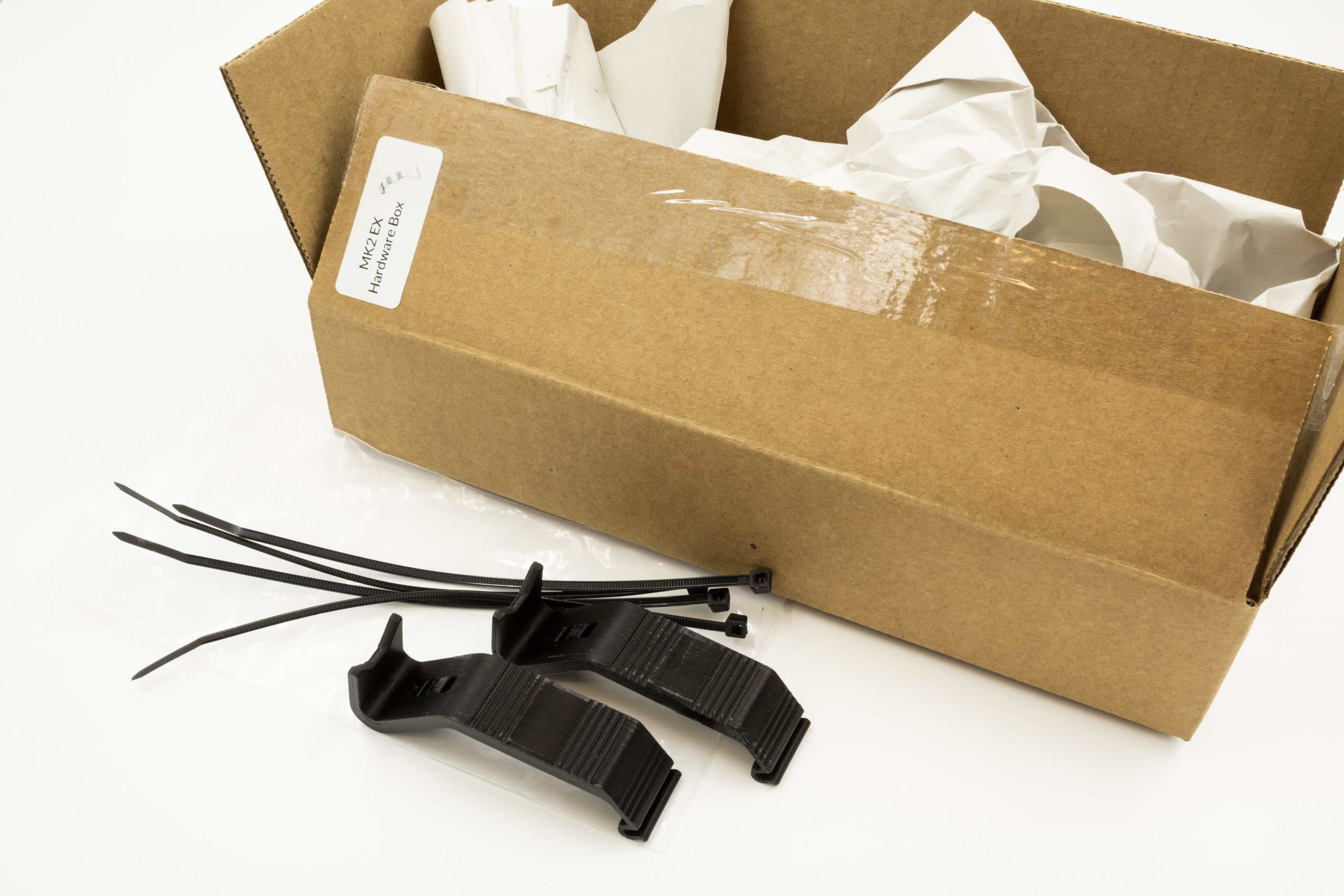
The ‘EX hardware box’ contains various hardware that is used when assembling the X-axis of your 48×30 machine, and the ‘MK2.5 EX hardware box’ contains other small parts specific to 48×30 MK2.5 LongMill. The ‘EX Drag chain box & cable box’ contains the longer 1400mm drag chain used on the X-axis, as well as some cable extensions. During sections of the assembly to follow, parts will be called from each of the boxes relevant to that section.
Continue to next step in main LongMill MK2.5 assembly manual
EX Delrin nut mounting

From within the EX hardware box, grab the much larger ‘EX Delrin anti-backlash nut’, as well as two ‘M5-nylock nuts’ from the green hardware bag. Just as the smaller spring-loaded anti-backlash nuts were assembled, this larger T12 nut will have two M5-nylock nuts fitted inside the two hexagonal pockets.
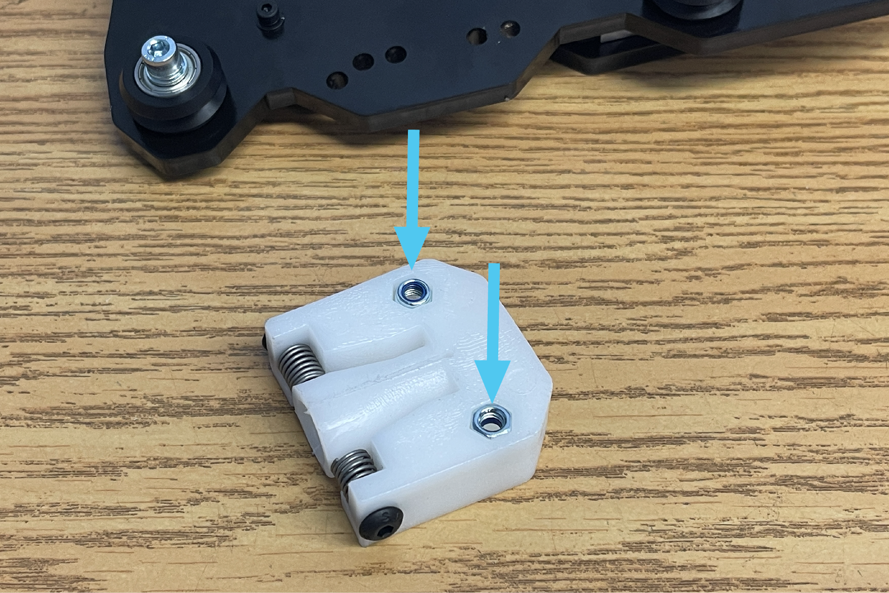
This T12 nut can now be installed onto the back of the X-gantry plate. Pass the two remaining M5-25mm bolts through the two outer holes in the X-gantry plate as shown threading into the M5 nylock nuts.
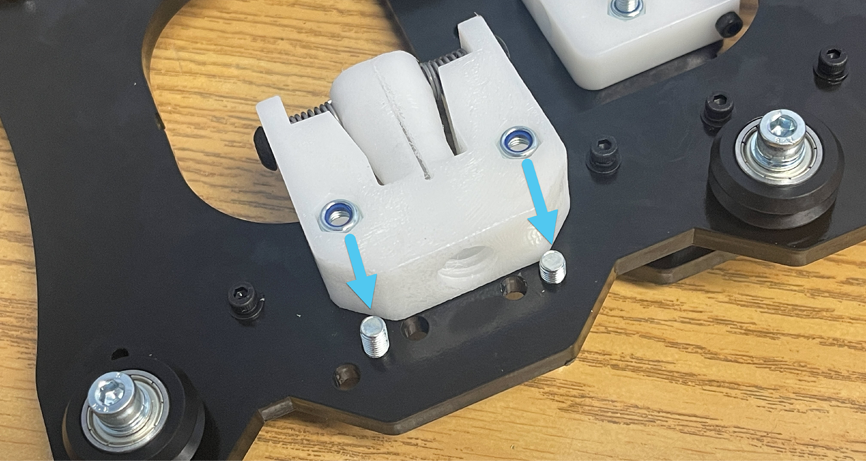
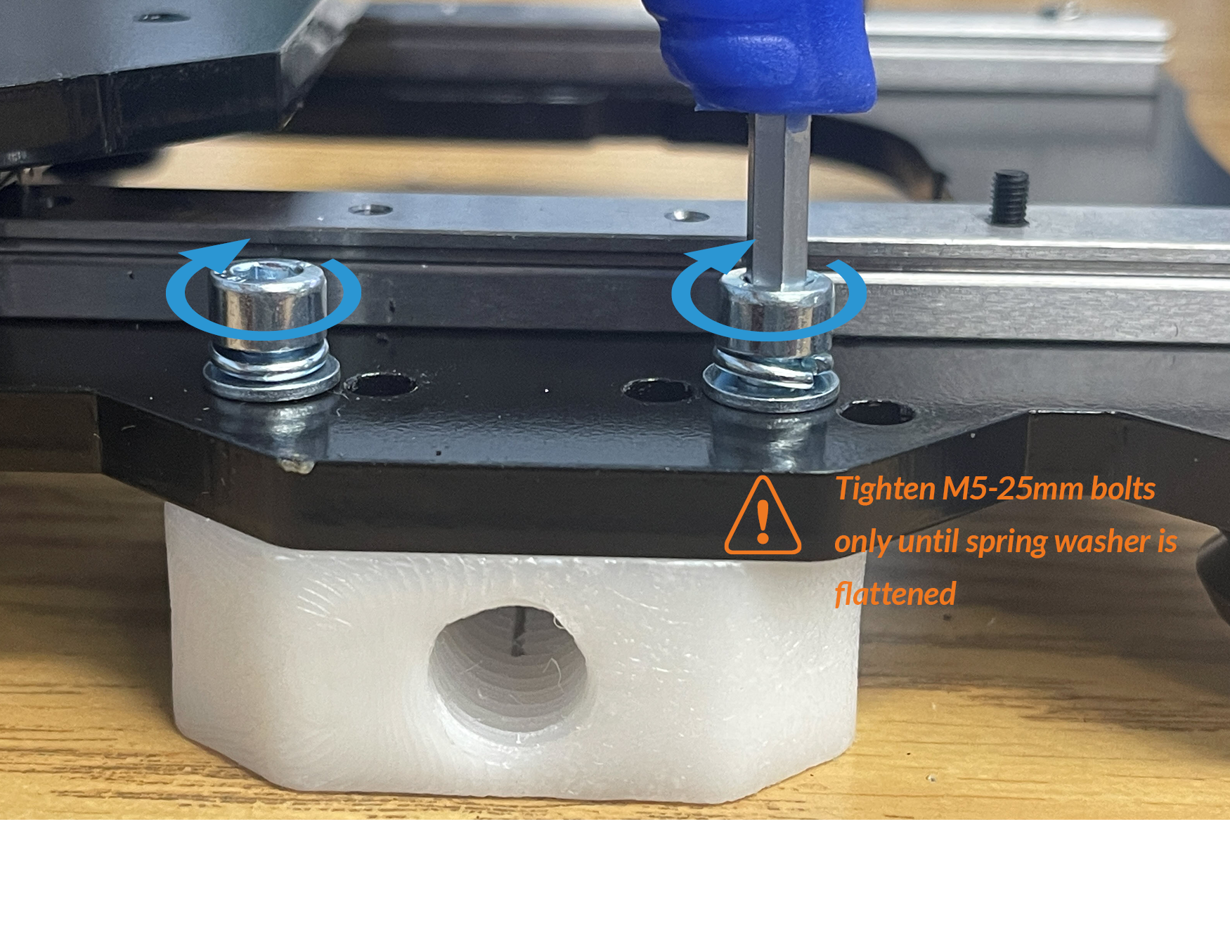
Tighten these bolts only until the spring lock washer has been flattened on the two M5-25mm bolts. These should only be snug as over-tightening will not allow the T12 nut to self-align and may bind up later on.
Continue to next step in main LongMill MK2.5 assembly manual
EX Y-gantry assembly
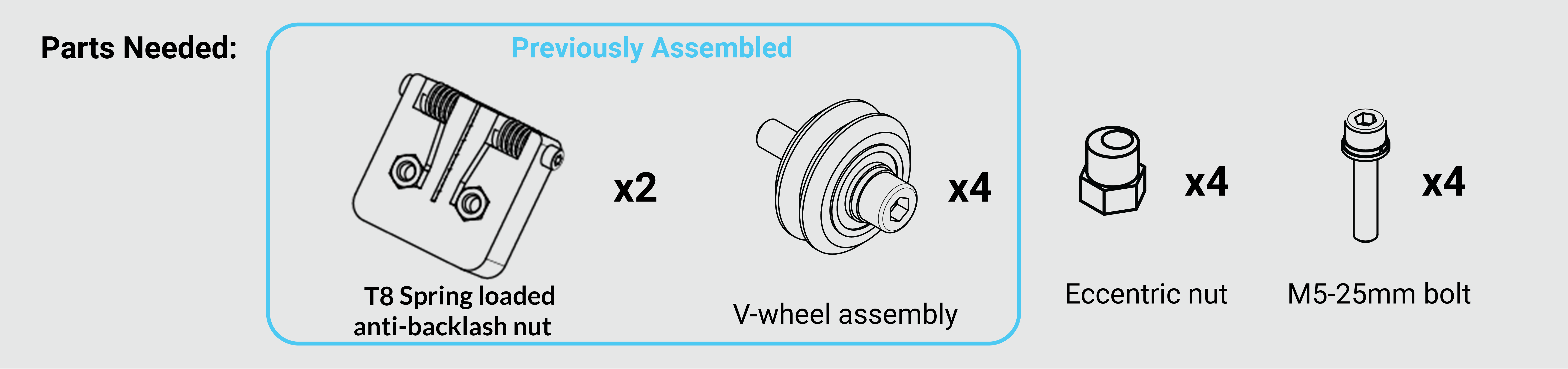
The Y-gantry plates will have two sets of holes used for installing the upper V-wheels assemblies. For the LongMill MK2.5 48×30, loosely install the upper V-wheel assemblies into the top two holes using eccentric nuts as shown below. Orient the inner holes of the eccentric nuts away from the bottom edge of the gantry.
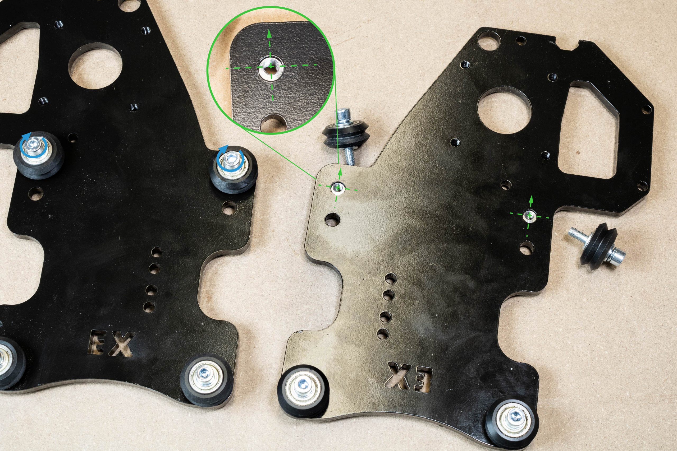
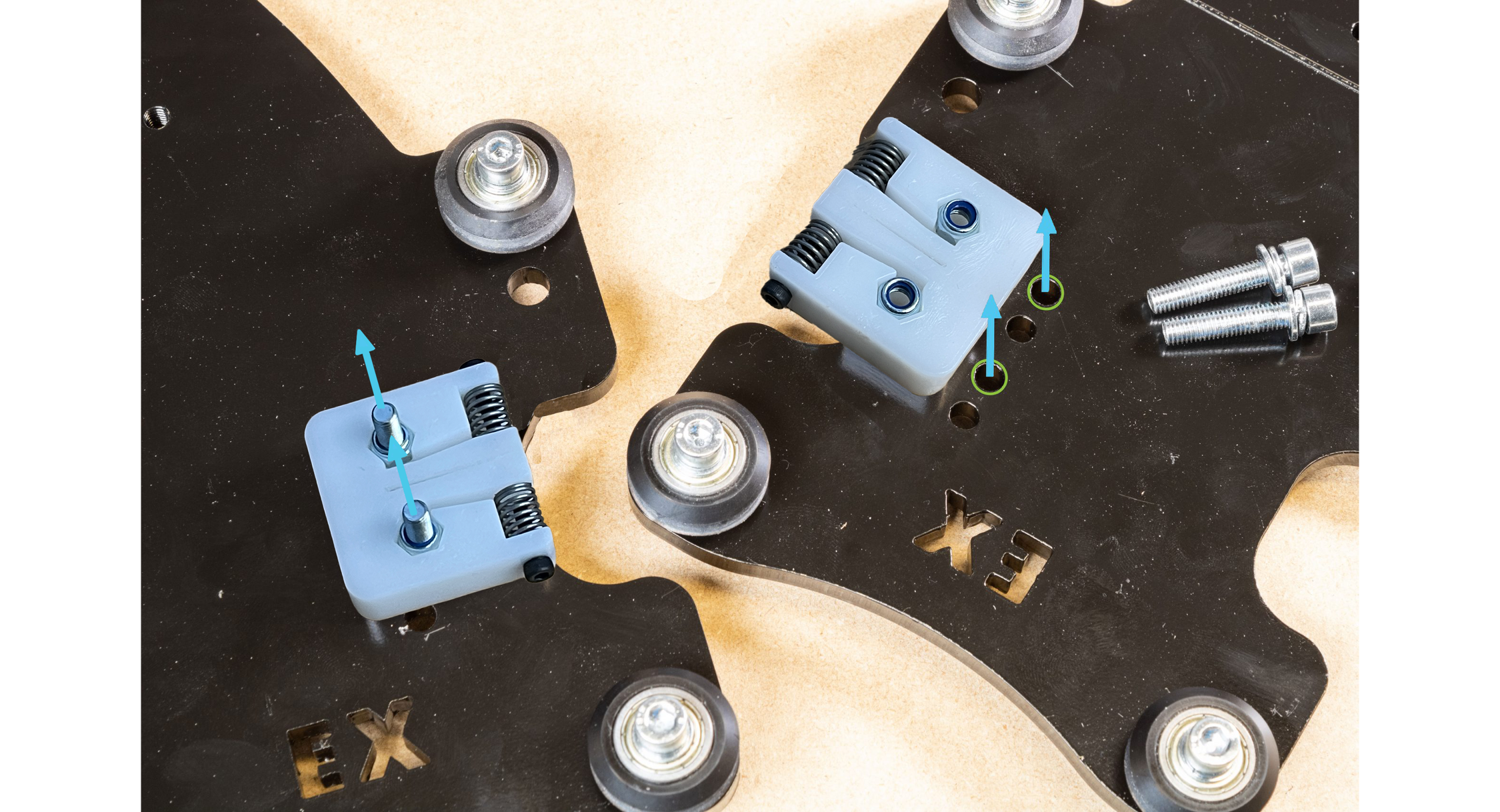
Each of these Y-gantry plates will also have two sets of holes used for mounting a T8 anti-backlash nut. Using the highlighted holes on each Y-gantry plate, attach each T8 nut to the back of each Y-gantry plate using two M5-25mm screws.
Continue to next step in main LongMill MK2.5 assembly manual
EX Lead screw assembly
X-axis motor mounting
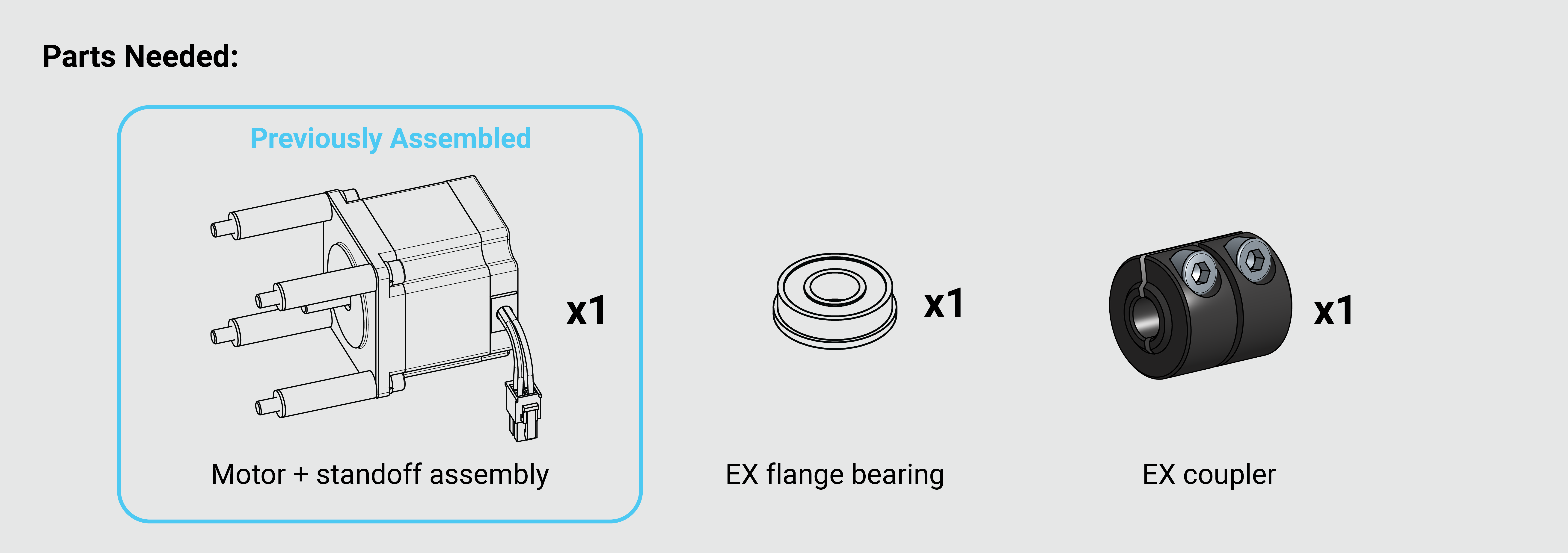
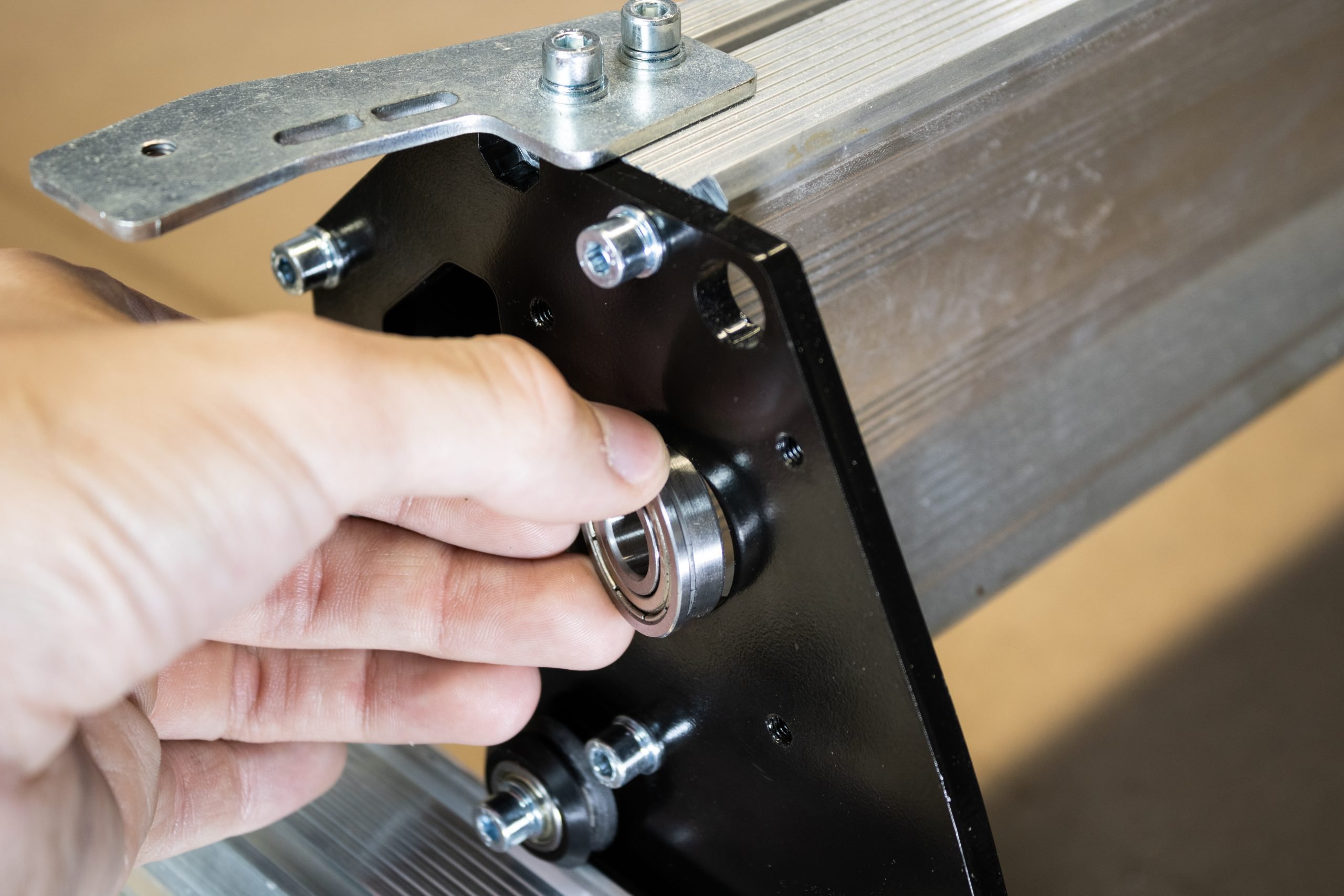
Grab an EX flange bearing and EX coupler from the EX hardware box, as well as one pre-assembled motor + standoff assembly.
Slide the EX flange bearing into the left Y-gantry plate.
Slide the EX coupler over the motor shaft. Do not tighten the bolts on the coupler, this will be left loose until the lead screw is installed.
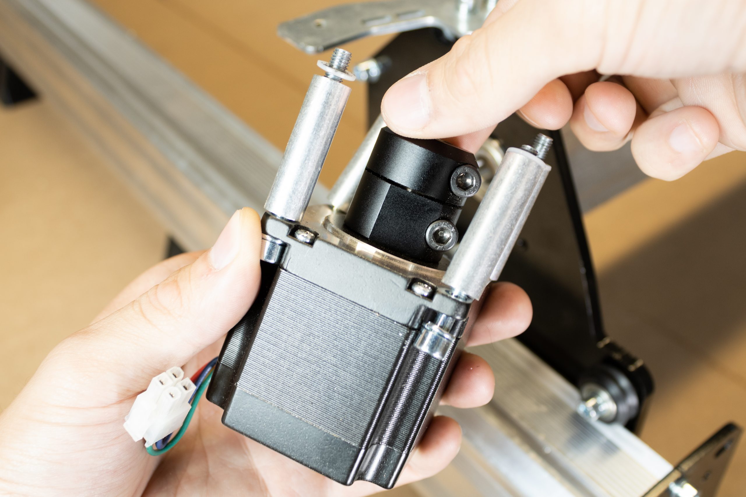
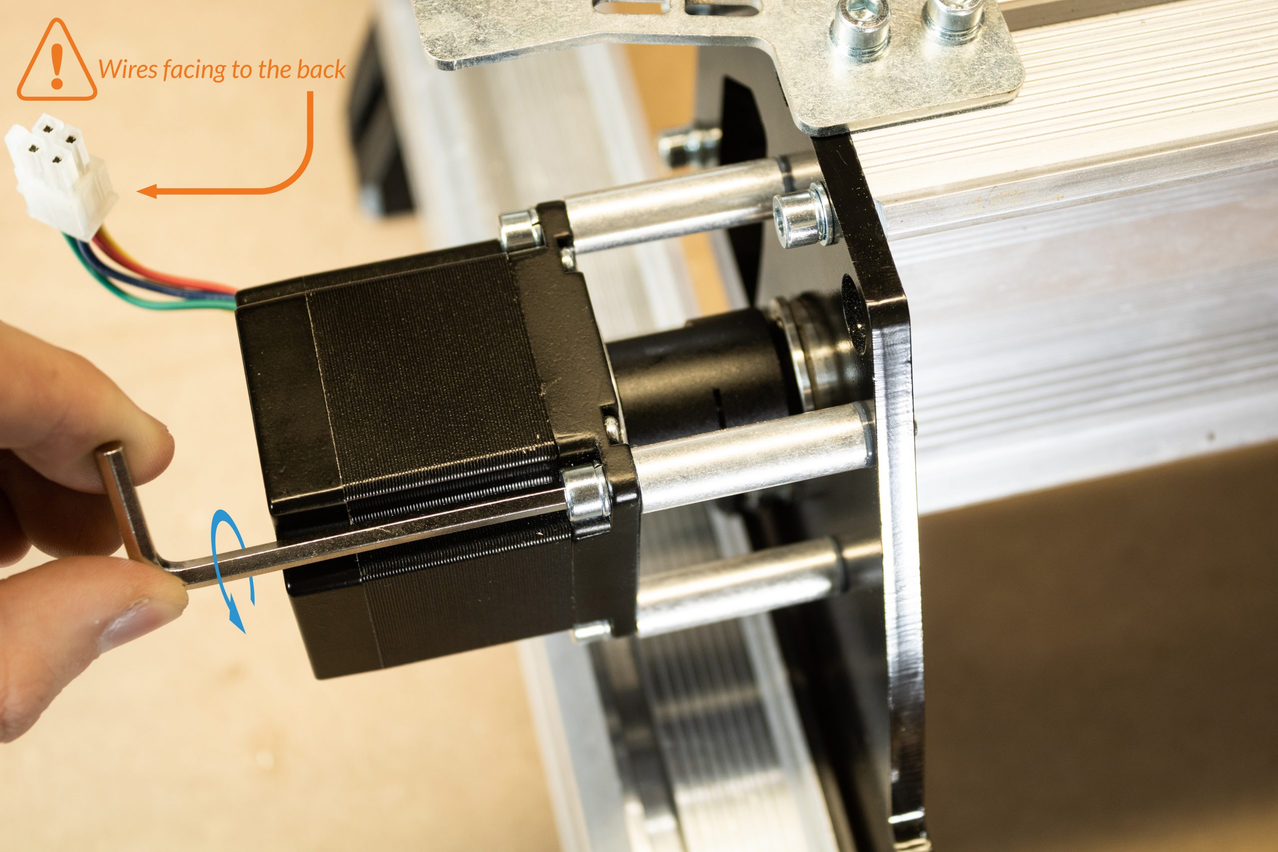
Mount this assembly onto the left Y-gantry plate, keeping the flange bearing in place. Orient the motor so the wires are facing towards the rear of the machine.
X-axis lead screw installation
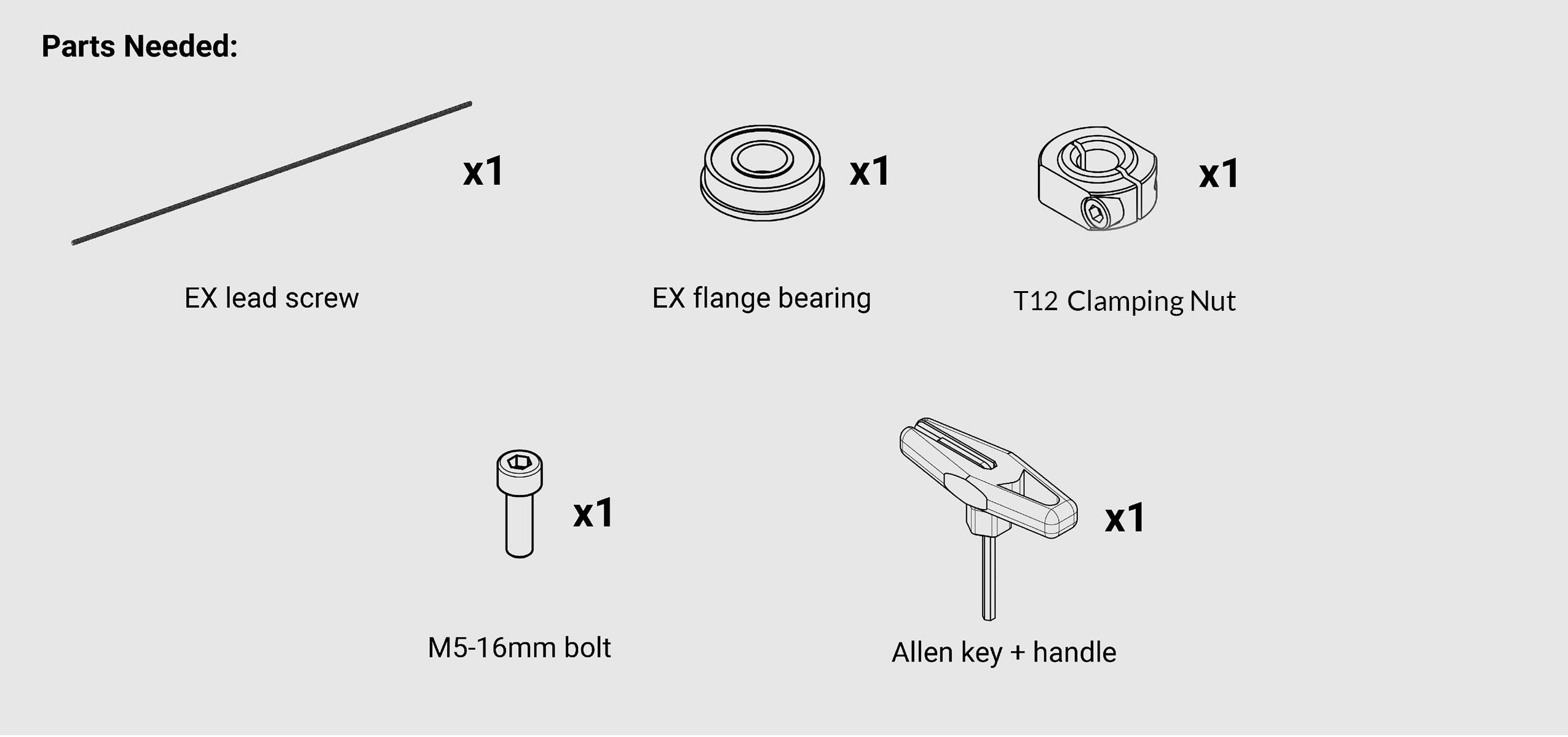
From the EX hardware box, grab the longer EX lead screw, as well as the second EX flange bearing, T12 Clamping nut with M5-16mm bolt, and Allen key + standoff assembly.
Pass the EX lead screw through the right Y-gantry plate towards the XZ-gantry assembly. Be careful not to bend the lead screw while doing this or handling it otherwise.
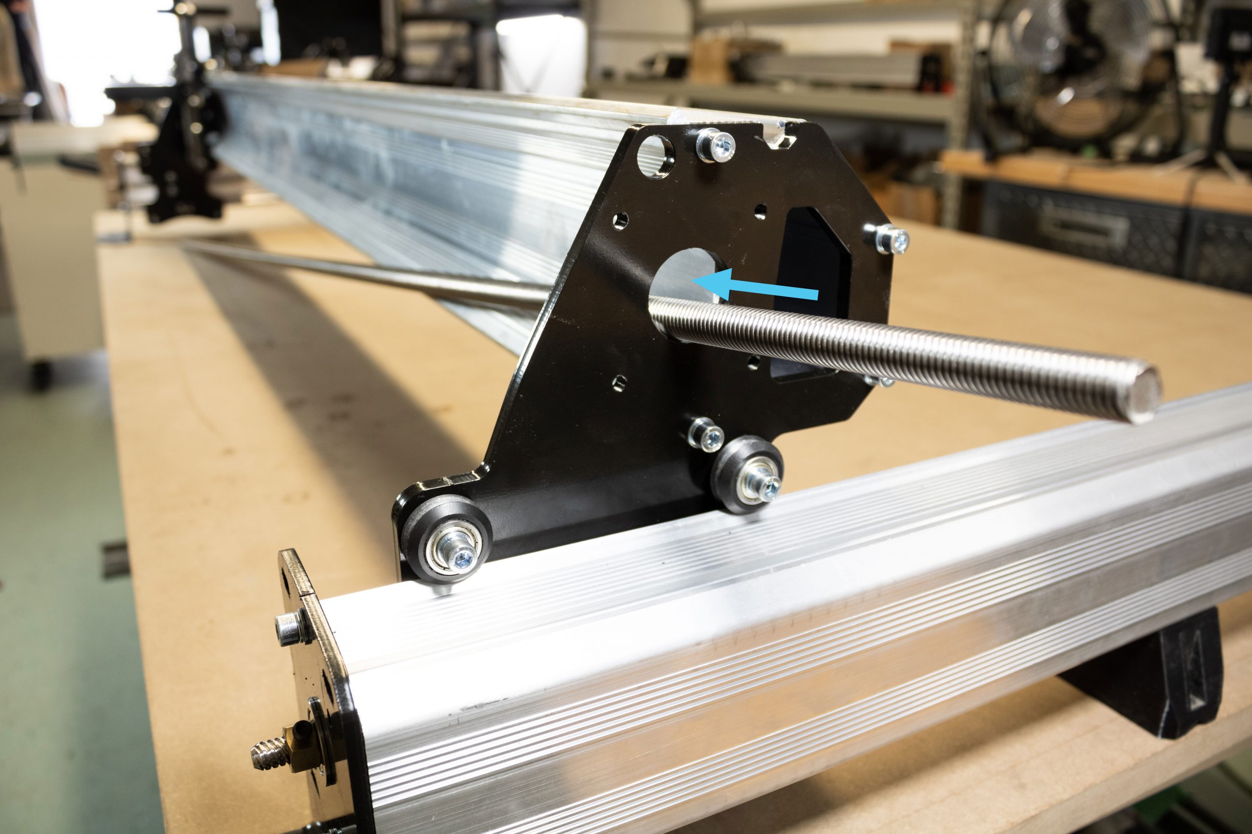
Begin threading the lead screw into the X-axis T12 anti-backlash nut.
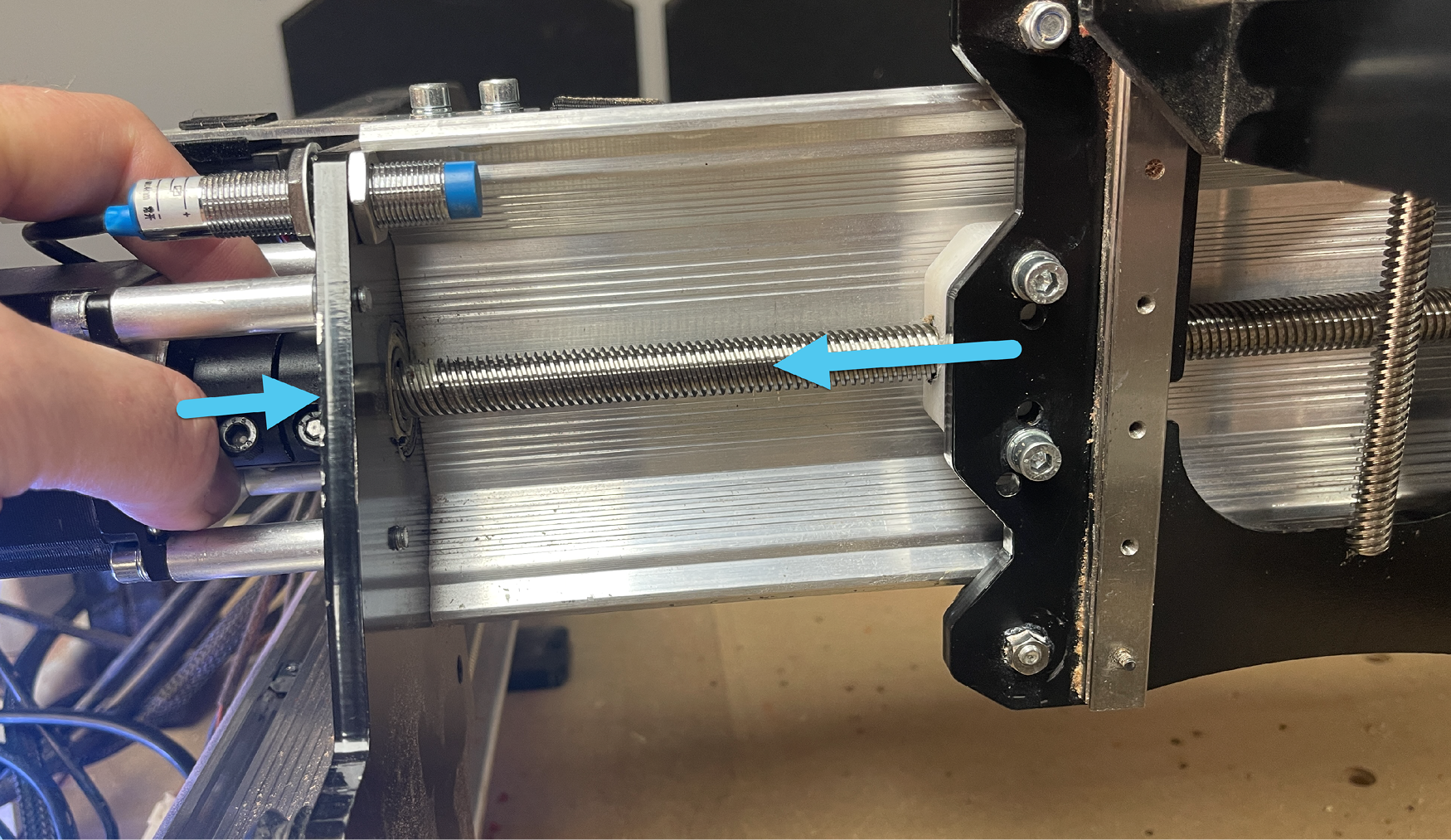
Continue threading the lead screw until it sticks out from the left side of the X-axis gantry. Slide the lead screw and X-axis gantry towards the left and pass the end of the lead screw into the flange bearing and into the motor coupler.
Push the coupler towards the right, and the X-gantry towards the left to ensure the lead screw is seated properly inside the coupler.
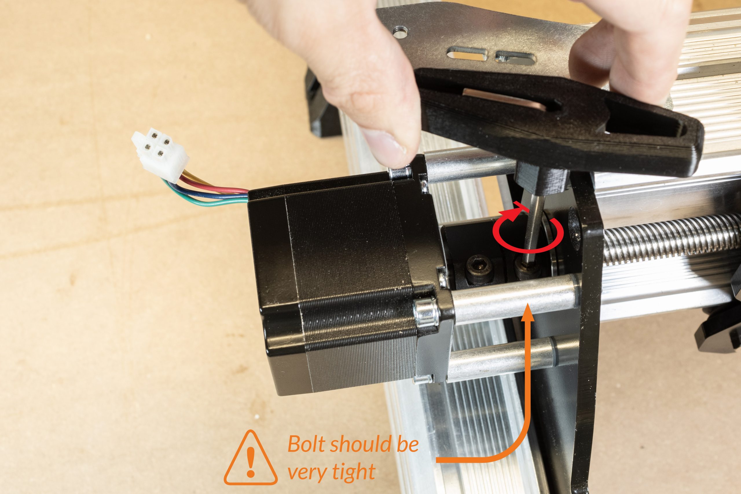
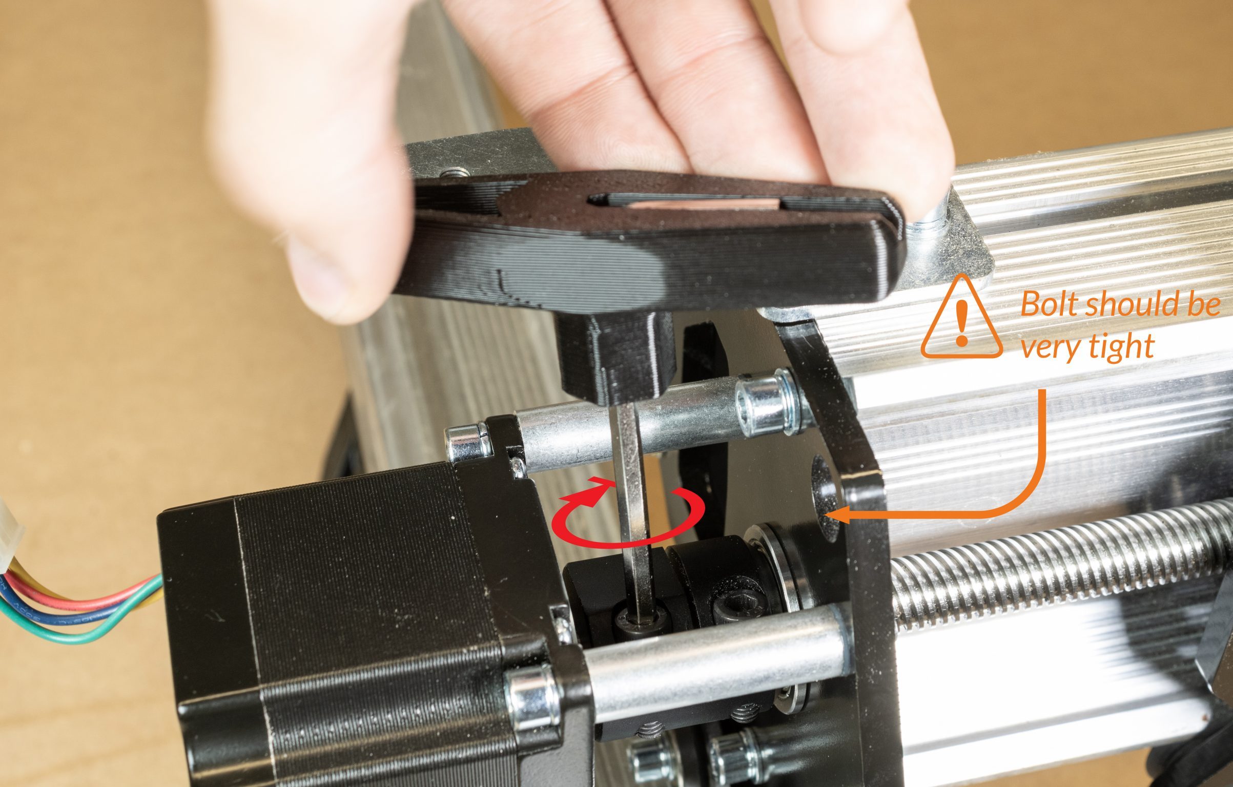
Tighten the motor coupler onto the lead screw. Use the Allen key + handle to do this as this bolt must be very tight.
Remove the bolt from the other end of the coupler completely.
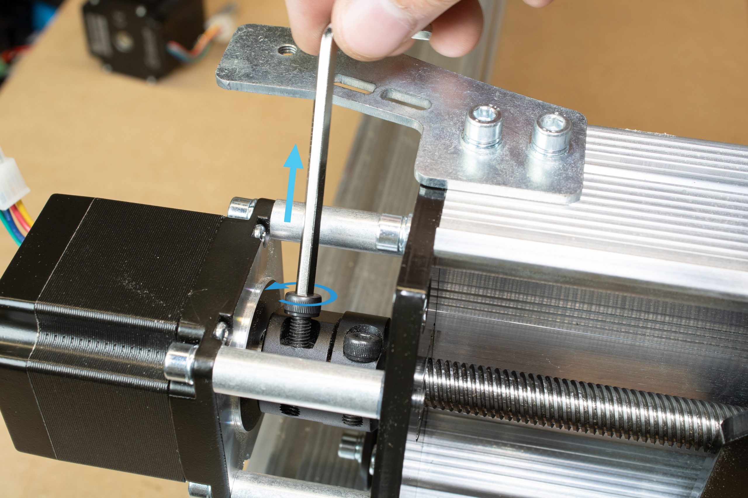
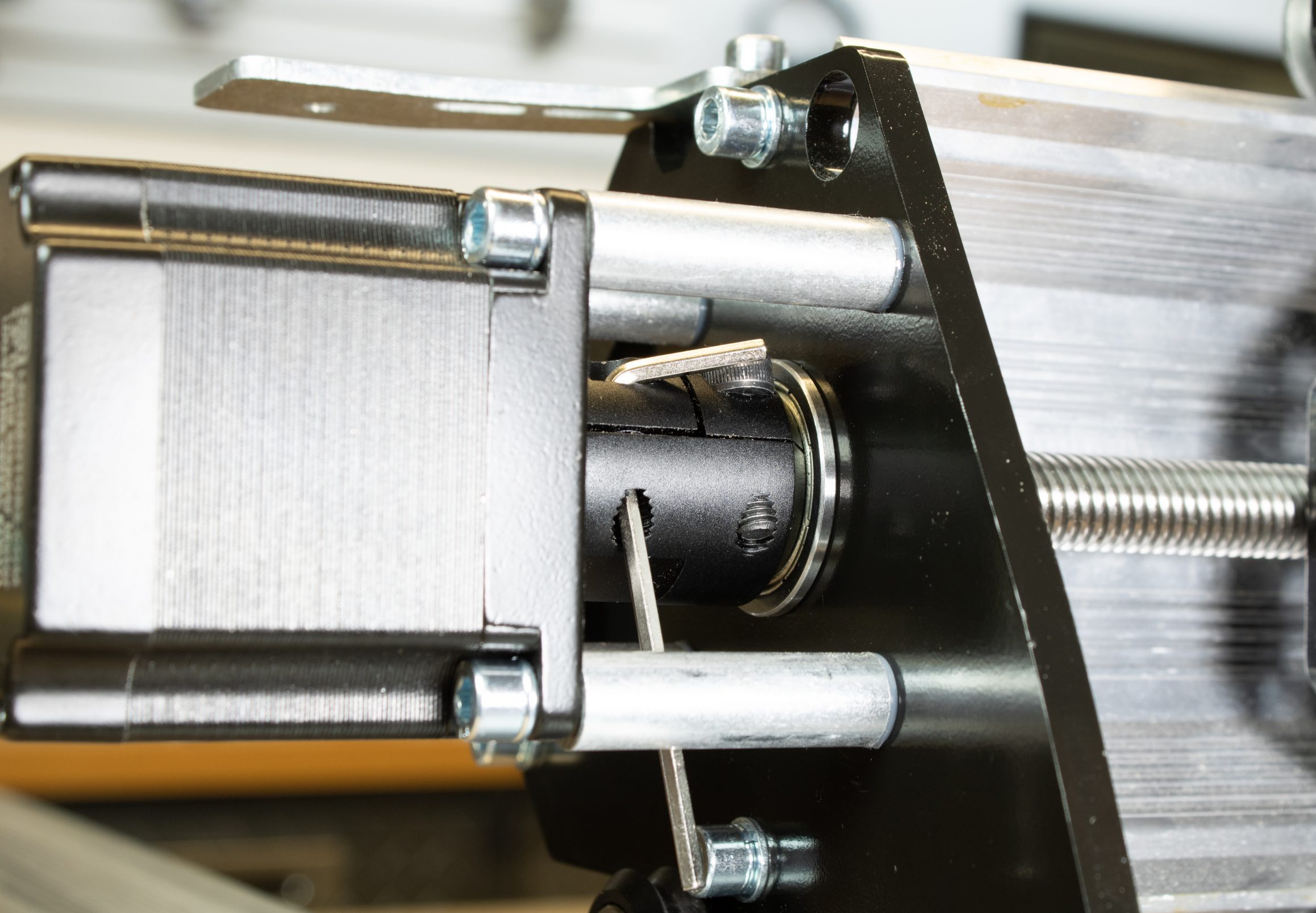
Pass an Allen key through this hole of the removed bolt to lock the coupler against the motor standoffs from rotating. Alternatively, a small screwdriver, bolt, or rod can be passed through instead. Locking the lead screw from rotating will allow for easier installation of the T12 clamping nut at the opposite side.
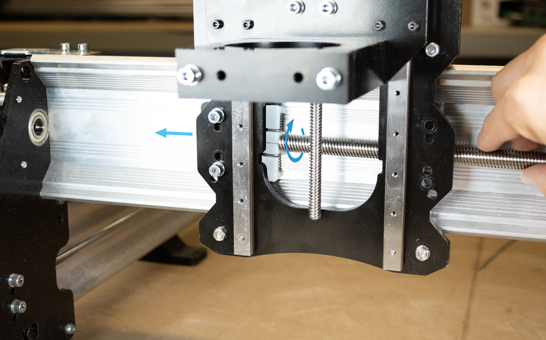
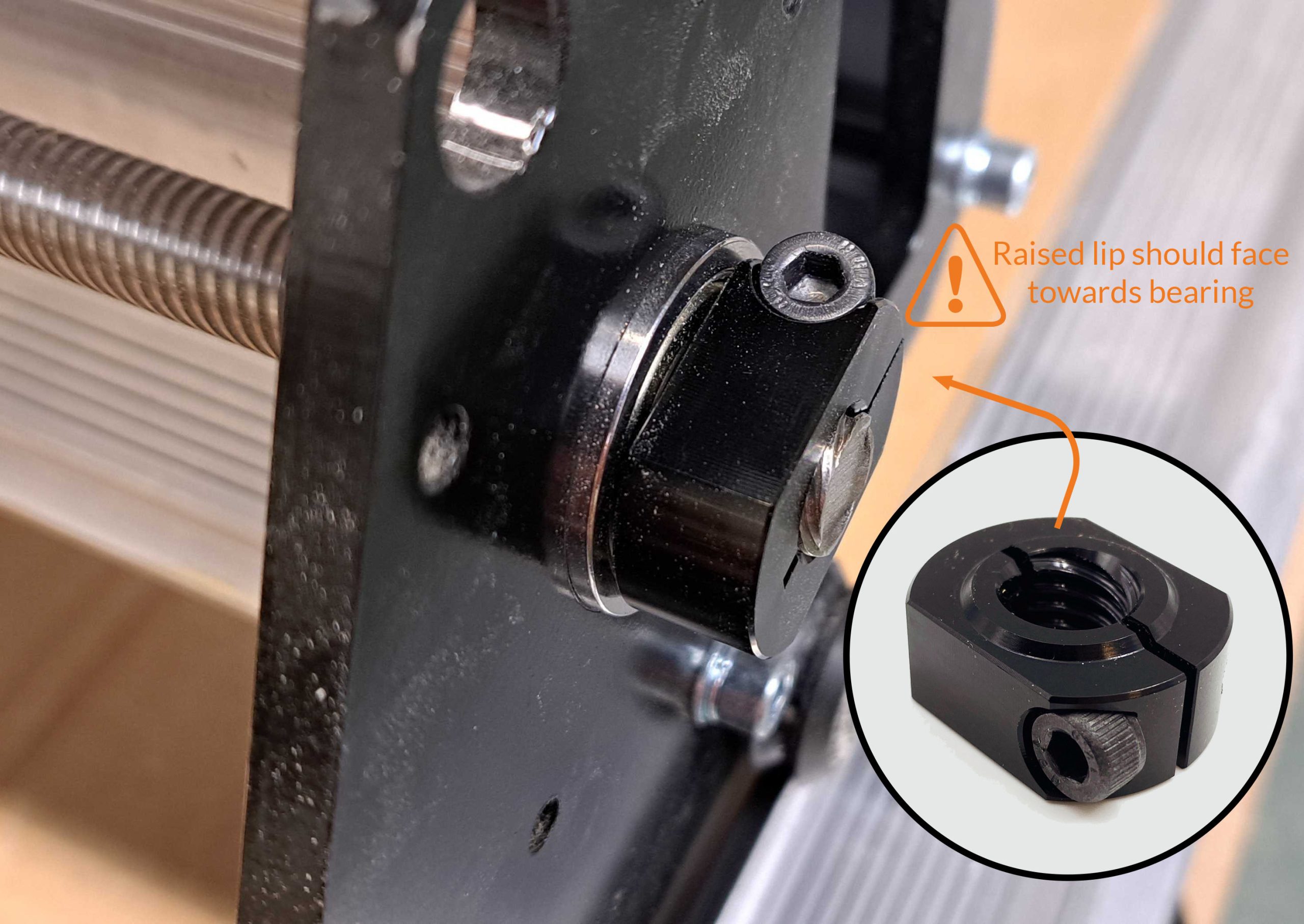
At the opposite side of the lead screw on the right Y-gantry plate, slide a flange bearing over the lead screw and into the Y-gantry plate.
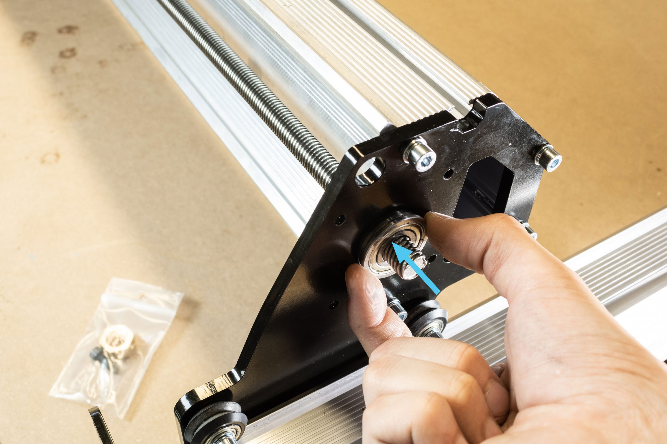
Grab the T12 Clamping nut and begin threading this onto the lead screw.
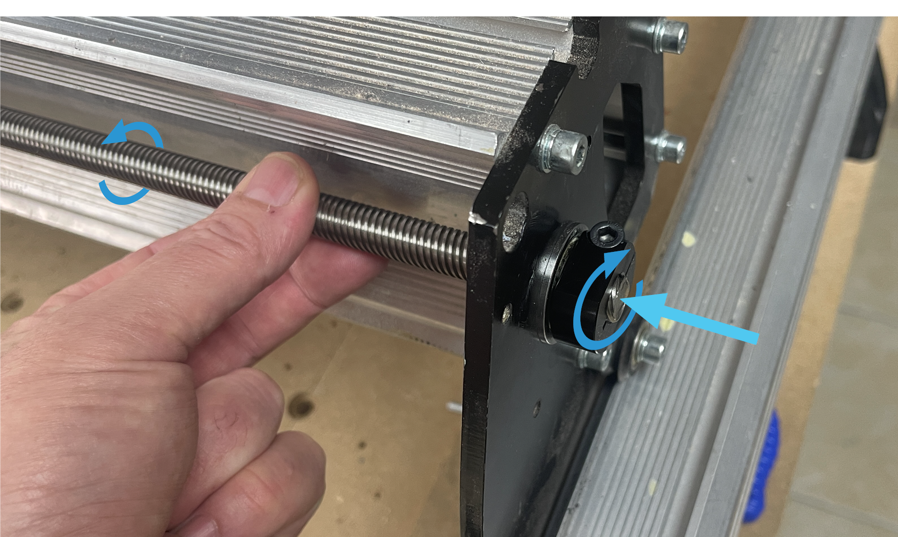
Using a 19mm, 3/4″ , or adjustable wrench, tighten this T12 Clamping nut only until the lead screw no longer has any side-to-side play. Then tighten the M5 locking bolt into the T12 locking nut to secure this.
Turn the lead screw by hand afterwards to make sure it spins freely. If you feel any significant resistance, undo the M5 locking bolt and loosen the T12 Clamping nut a small amount.
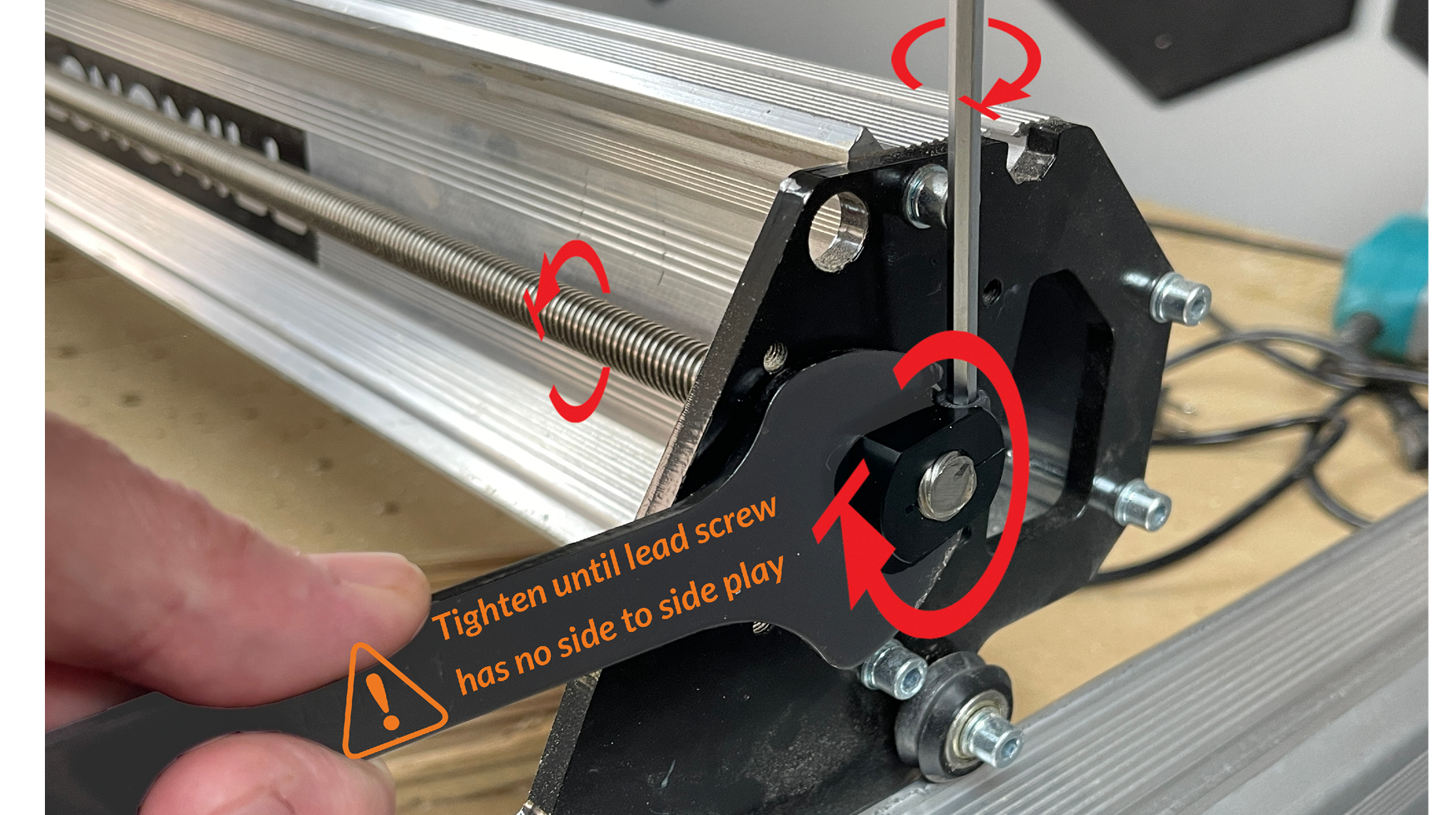
Ensure that this clamping nut is threaded on with the small raised lip facing towards the bearing.
Remove any screwdrivers, Allen keys, or bolts from the coupler on the opposite side to allow the coupler and lead screw to freely rotate. Then reinstall the M5-16mm bolt into the motor side of the coupler and tighten this using the Allen key handle – this should be tightened very tight.
Continue to next step in main LongMill MK2.5 assembly manual
Cable extension installation
Connecting and routing cables
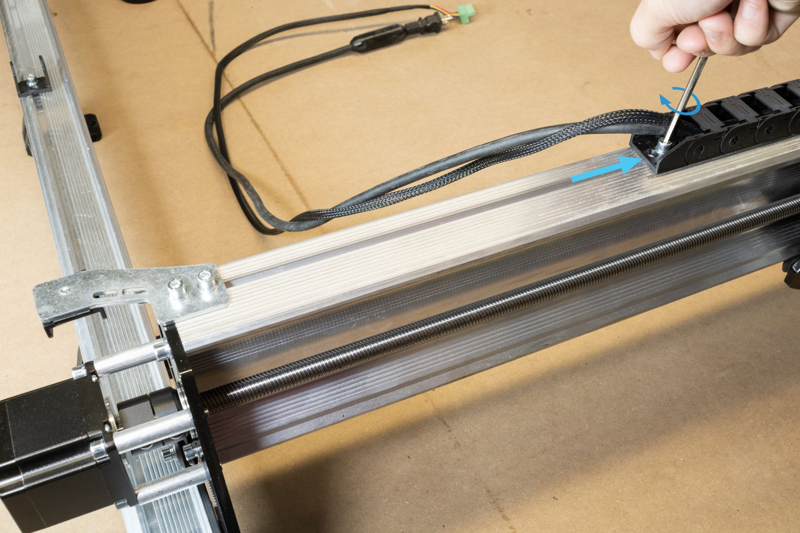
Loosen the bolt mounting the X-axis drag chain onto the X-axis rail and slide this end link roughly 10″ towards the middle of the rail. Re-tighten this mounting bolt after.
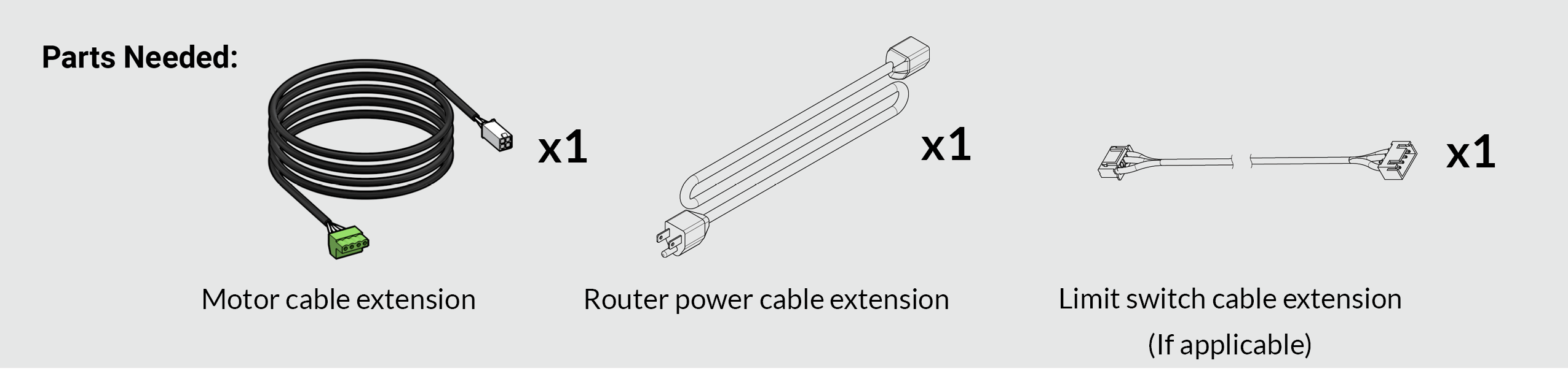
Grab the router power extension cable and motor cable from the drag chain & cable box.
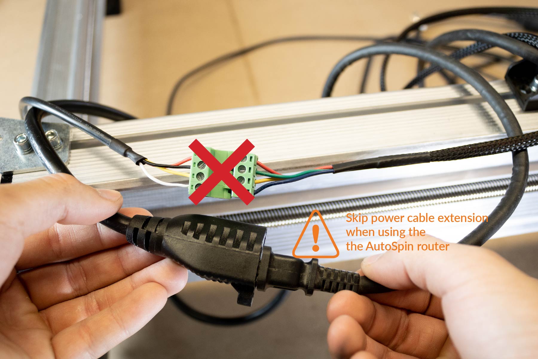
The Makita’s motor cable has been updated to not need an extension cable, it can now reach all the way to the controller!
If you have an AutoSpin router, the cable should also reach all the way to the outlet, so you don’t need to install the power cable extension.
Only applicable if installing the inductive sensor kit as well:
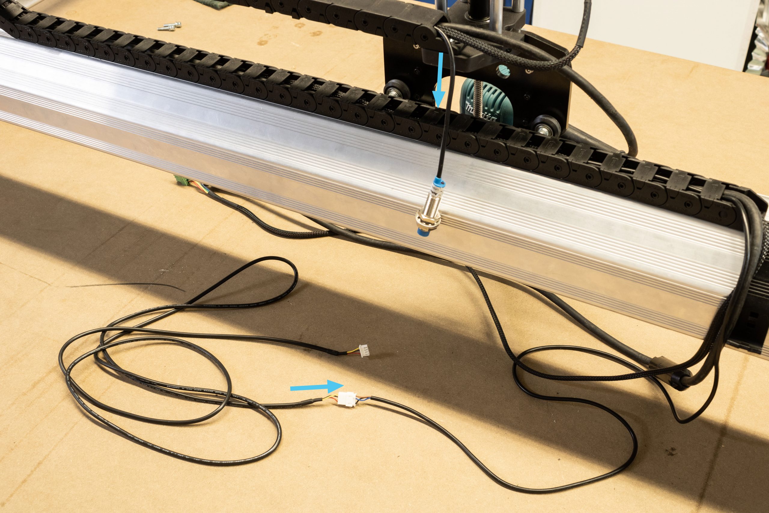
Install the Z-axis limit switch now. Grab the limit switch cable extension from the EX drag chain & cable box, as well as one of the three inductive sensors from within the kit.
Route one inductive sensor cable through the X-axis drag chain, leaving some slack at the sensor end for mounting later on. Install the included limit switch extension cable as shown below to extend this cable. The excess cable length will be bundled with the Z-axis motor cable and router power cable in the next section.
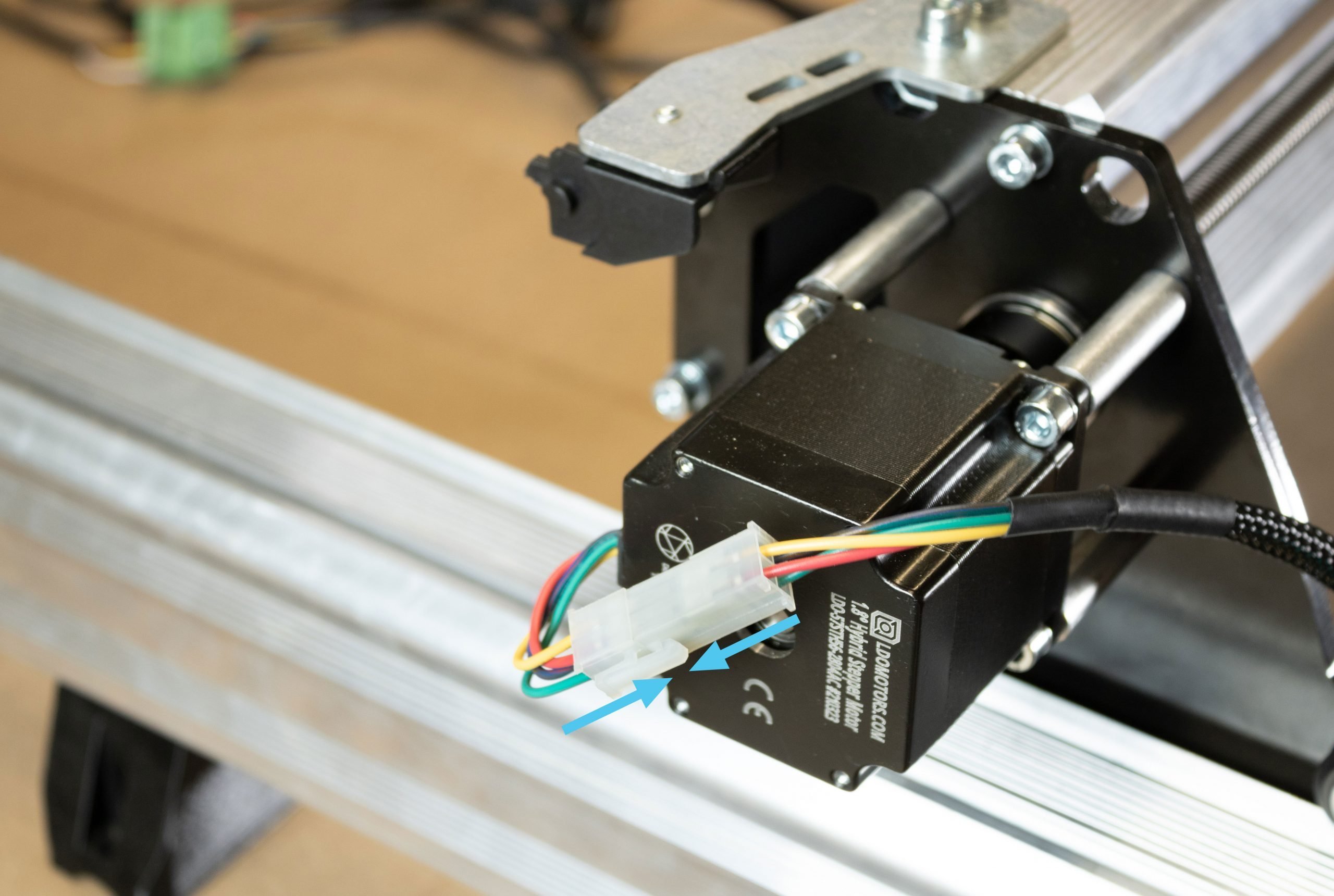
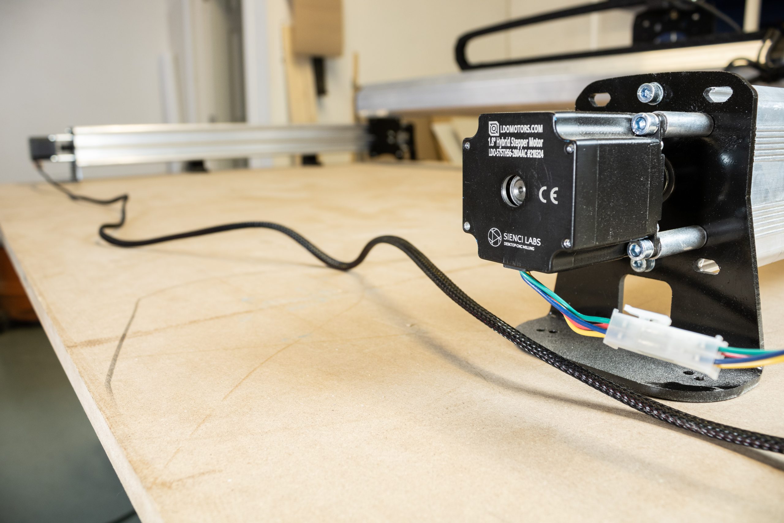
Grab the motor cable and connect it to the X-axis motor.
If you have a Makita router, connect the power extension to the router’s power cord. The AutoSpin is long enough, so no extension needed!
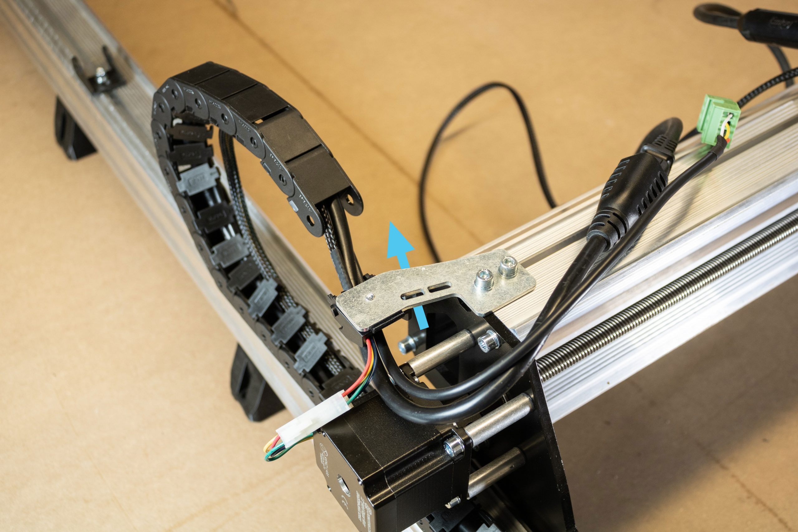
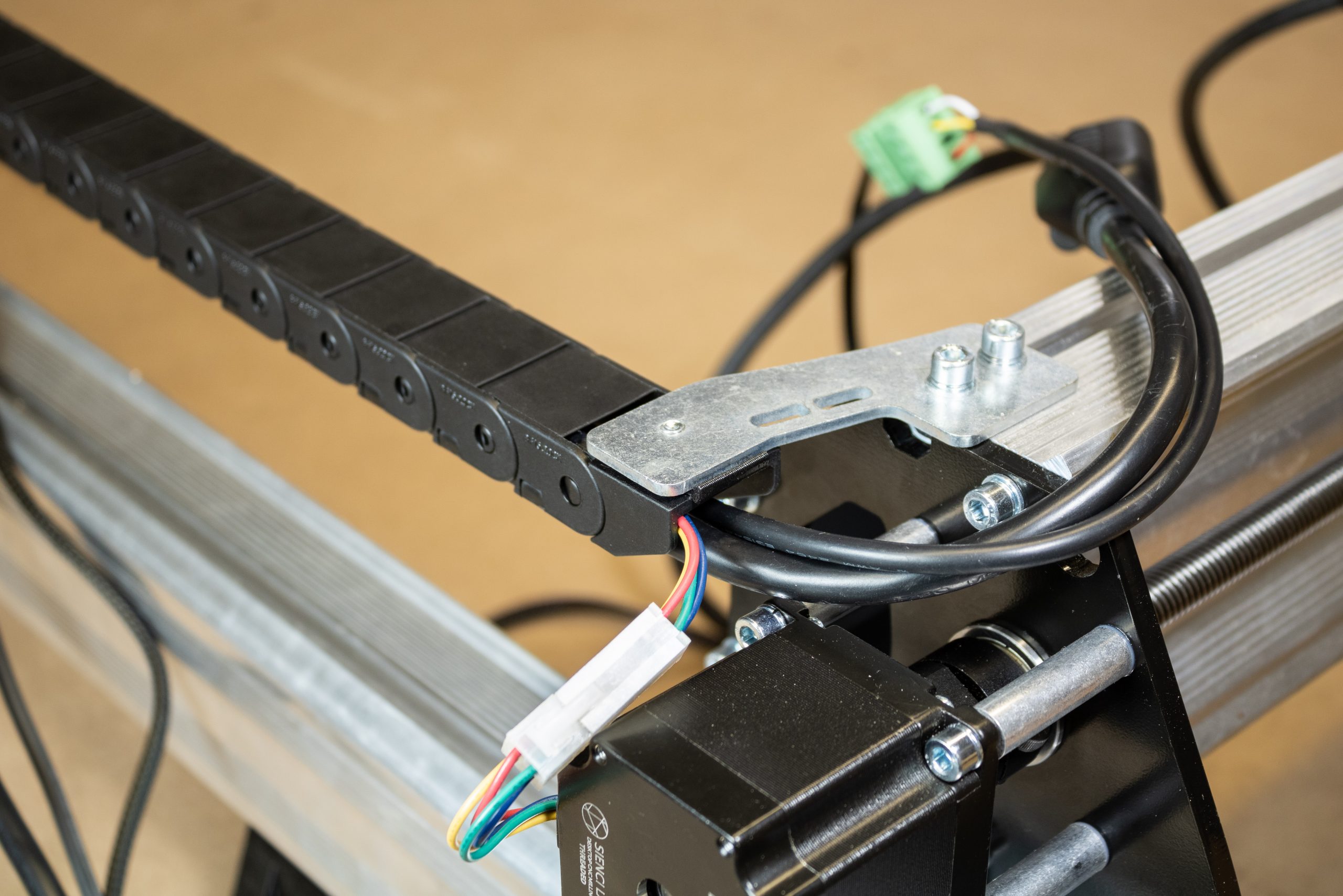
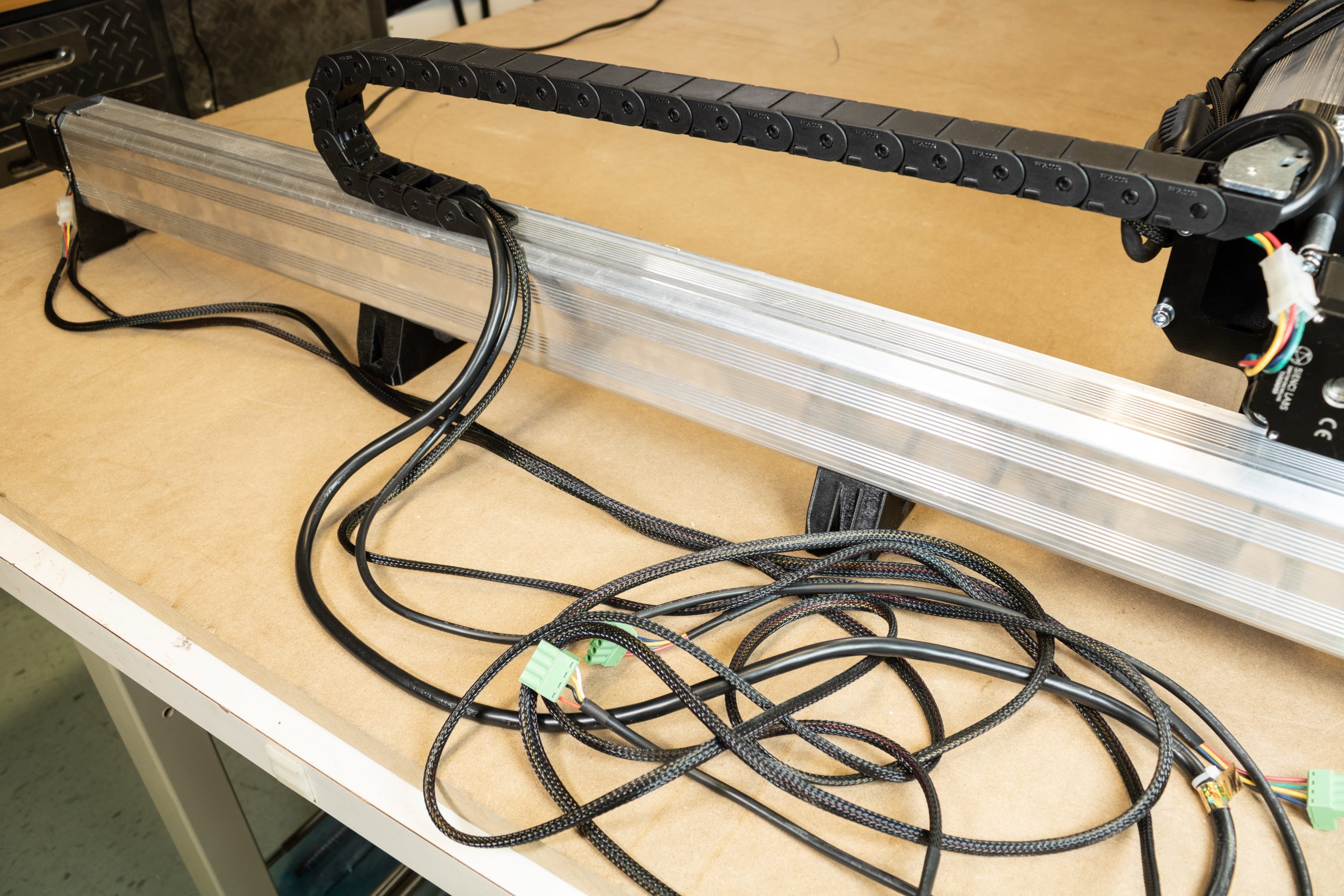
Begin routing the router power cable, signal cable and X-axis motor cable into the shorter Y-axis drag chain. Fit these cables underneath the drag chain mount. Allow the power plug to sit outside of the Y-axis drag chain as shown. This excess bundling of cable will be organized neatly in the next step.
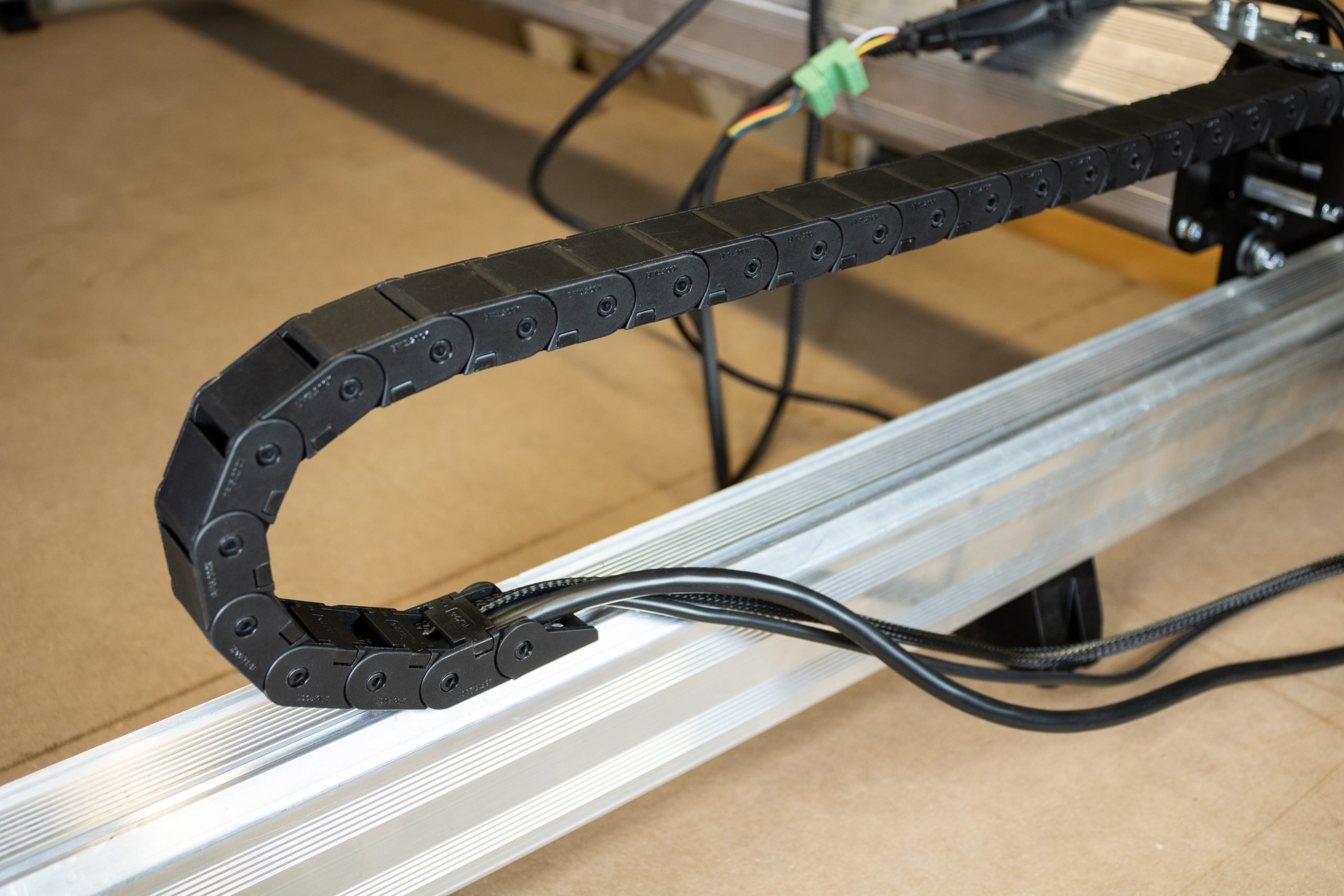
Secure the cables inside the drag chain by re-clipping each clip, then attach the drag chain onto the start and end links mounted on the machine.
Organizing excess cable lengths

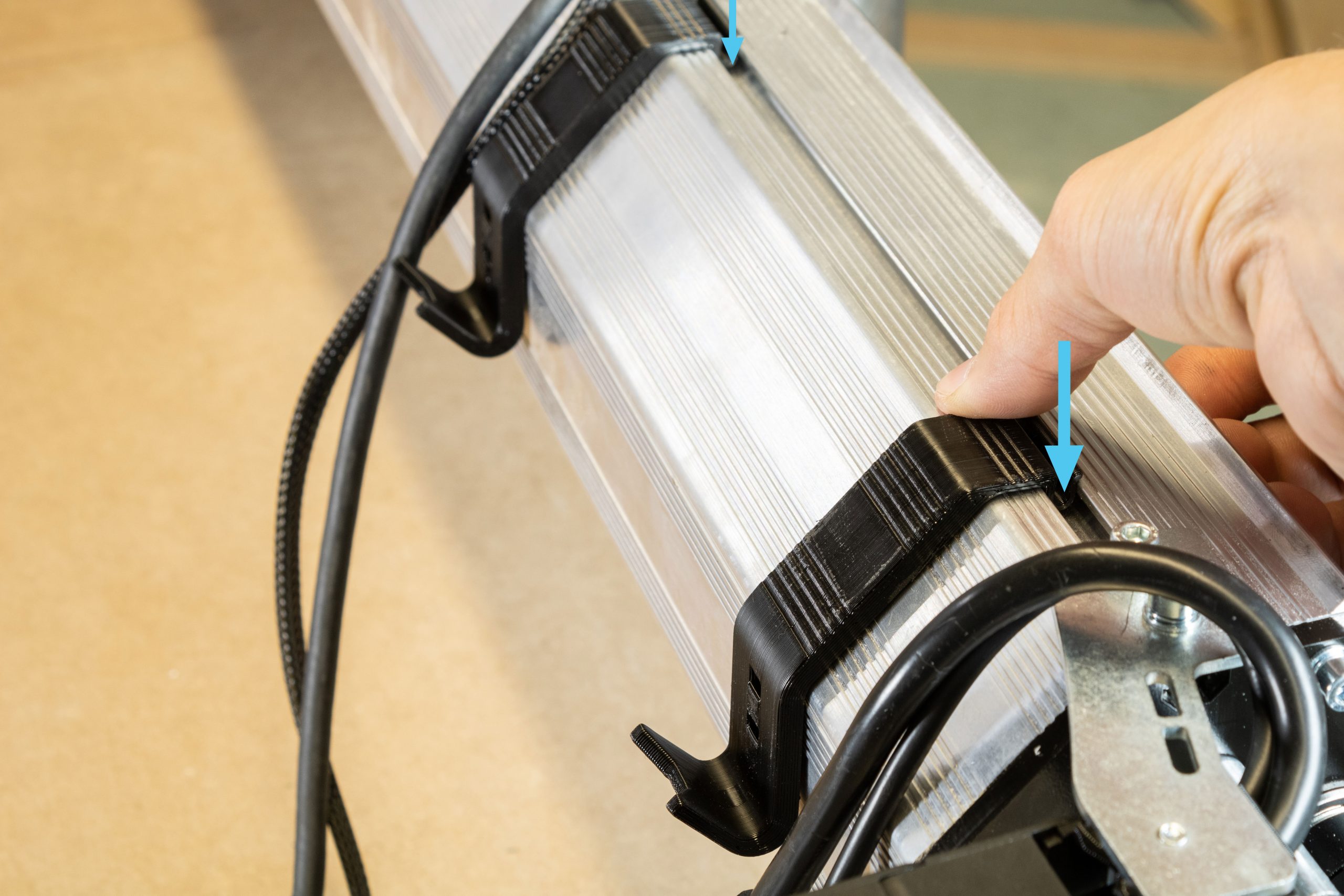
Grab the two ‘cable hangers’ from the EX hardware box. Align the clip portion of these into the T-slot on the X-rail and press directly downwards firmly to clip these in place. These are installed between the X-axis drag chain end link and the steel drag chain mount as shown.
Should you need to unclip these hangers for any minor adjustments, pull the bottom edge of the hanger upwards to rotate and unclip from the T-slot.
Get two zip ties from the X-axis EX hardware bag and insert these into the lower hole in each of the drag chain mounts.
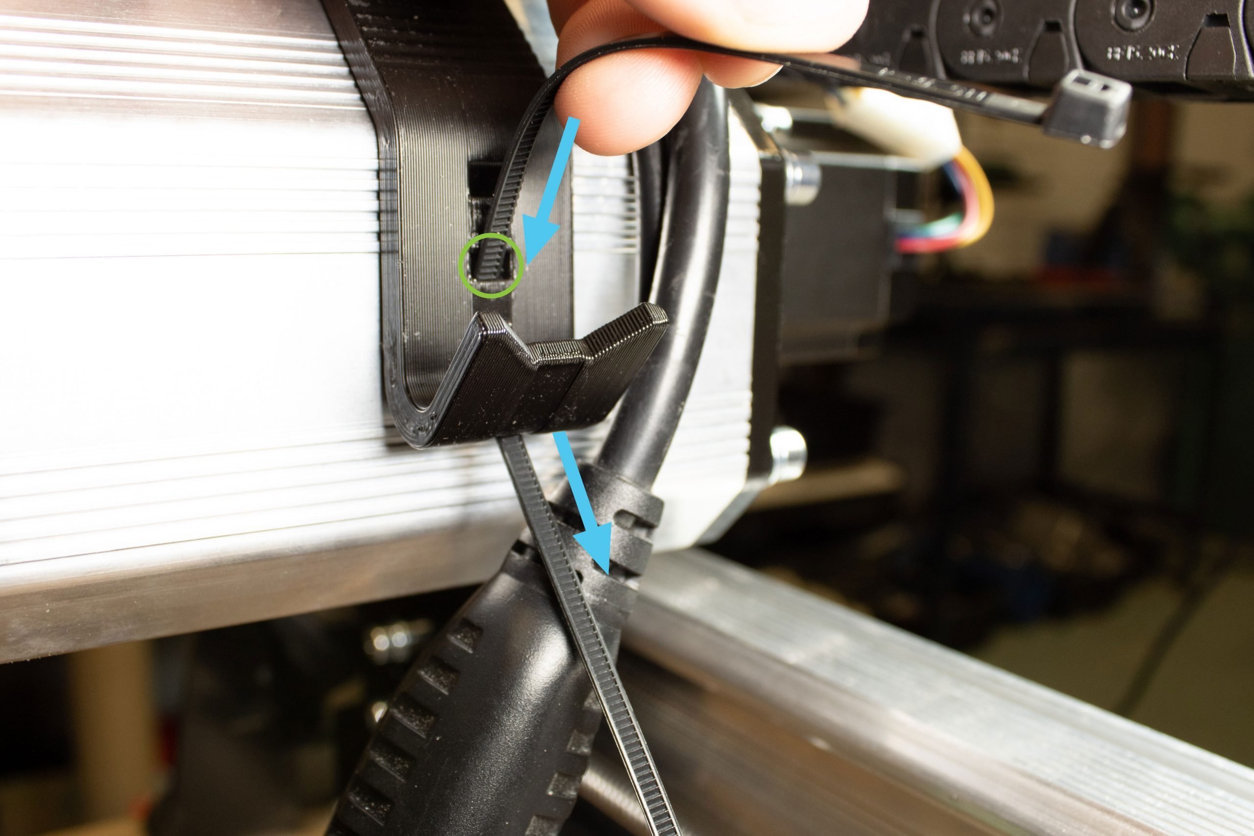
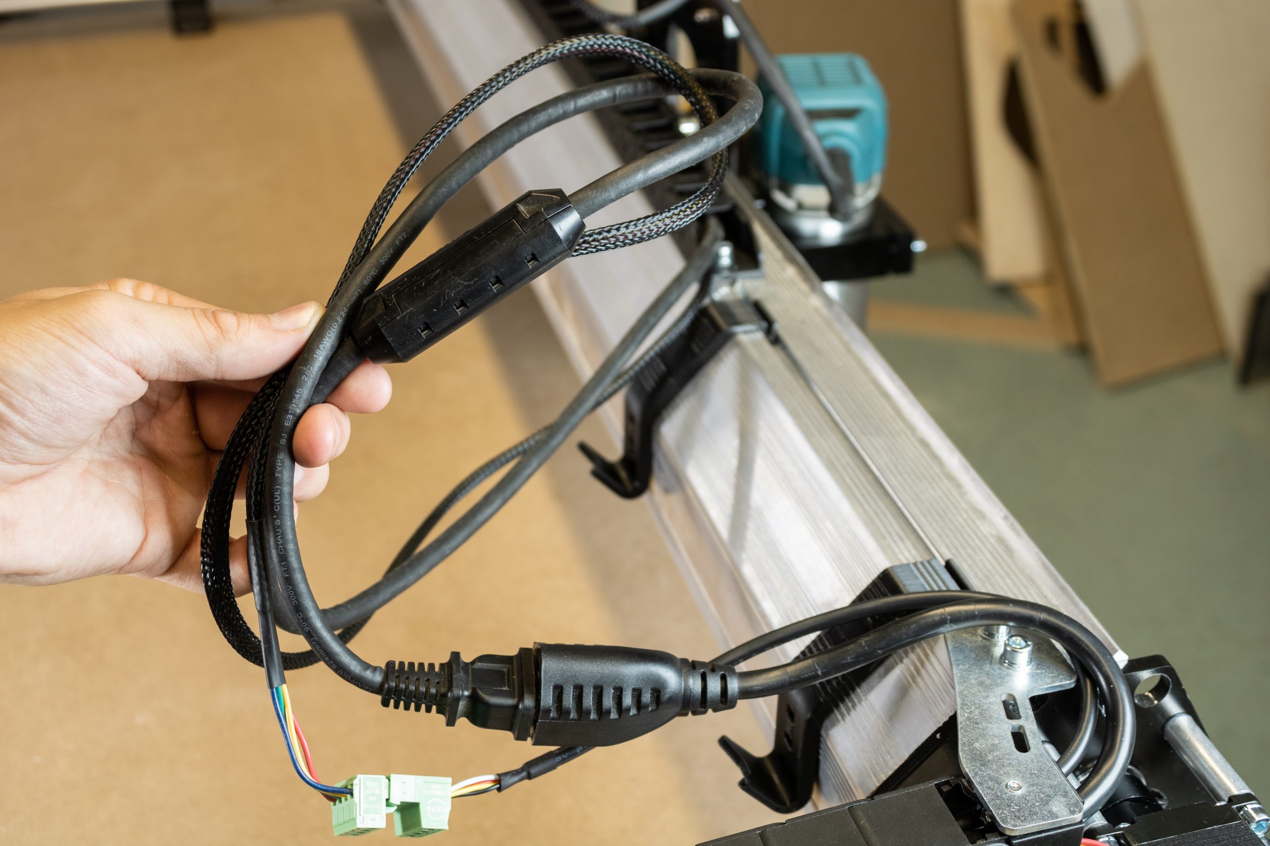
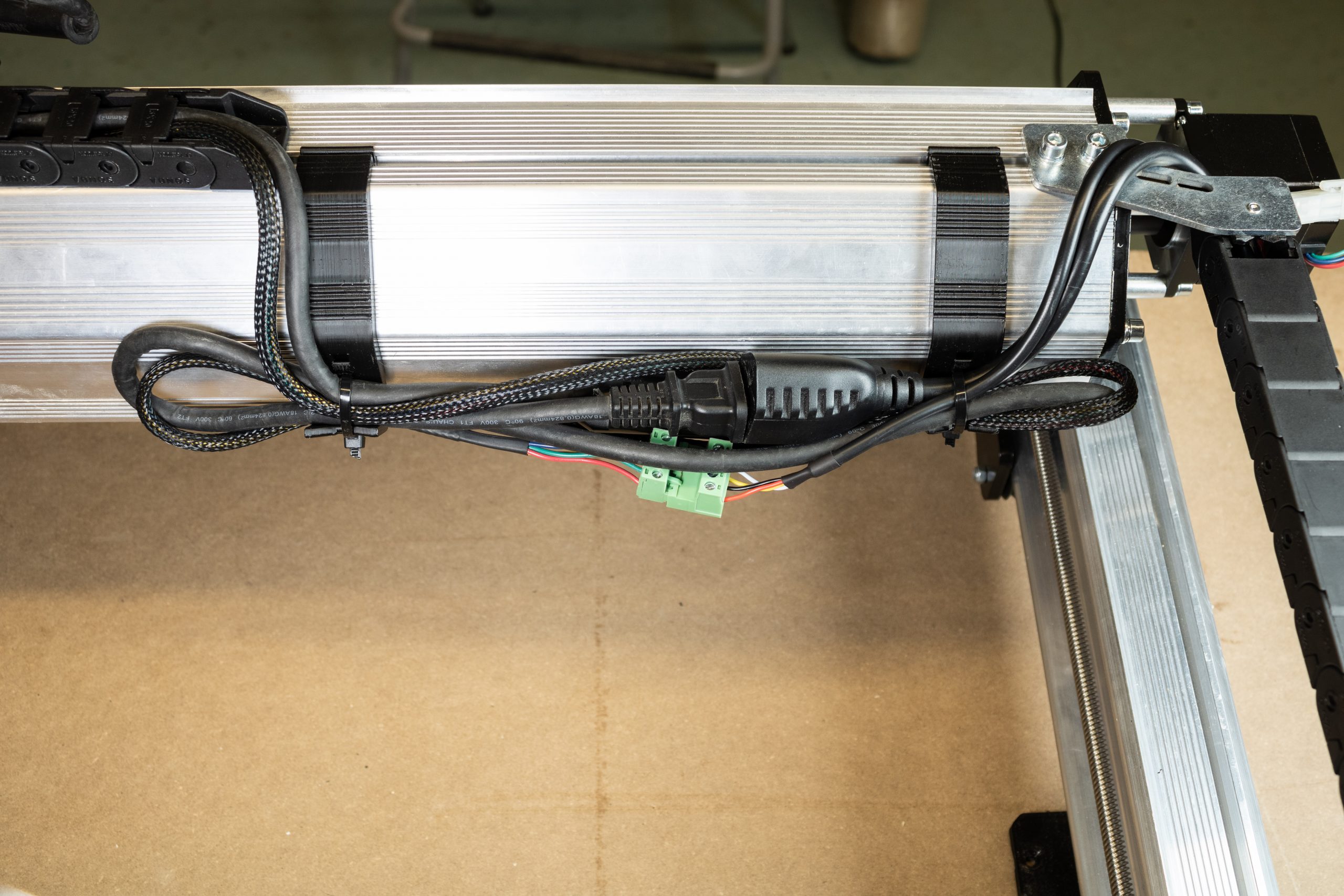
Straighten out the excess cabling into one bunch, then fold this in half.
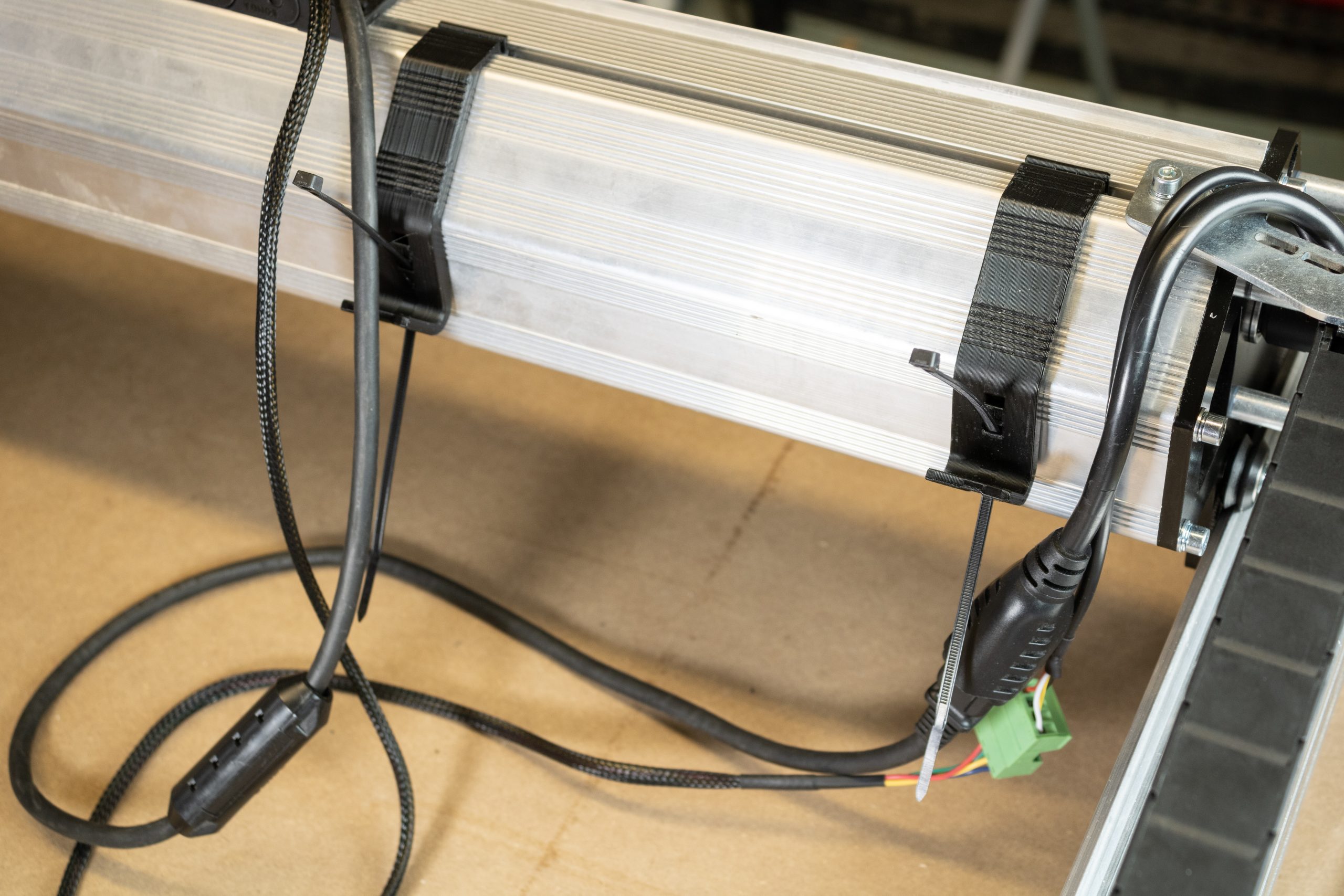
The folded bunch of excess cables can then be secured into both cable hangers. Tighten the two zip ties at each hanger. Trim the excess length from the zip ties once finished.
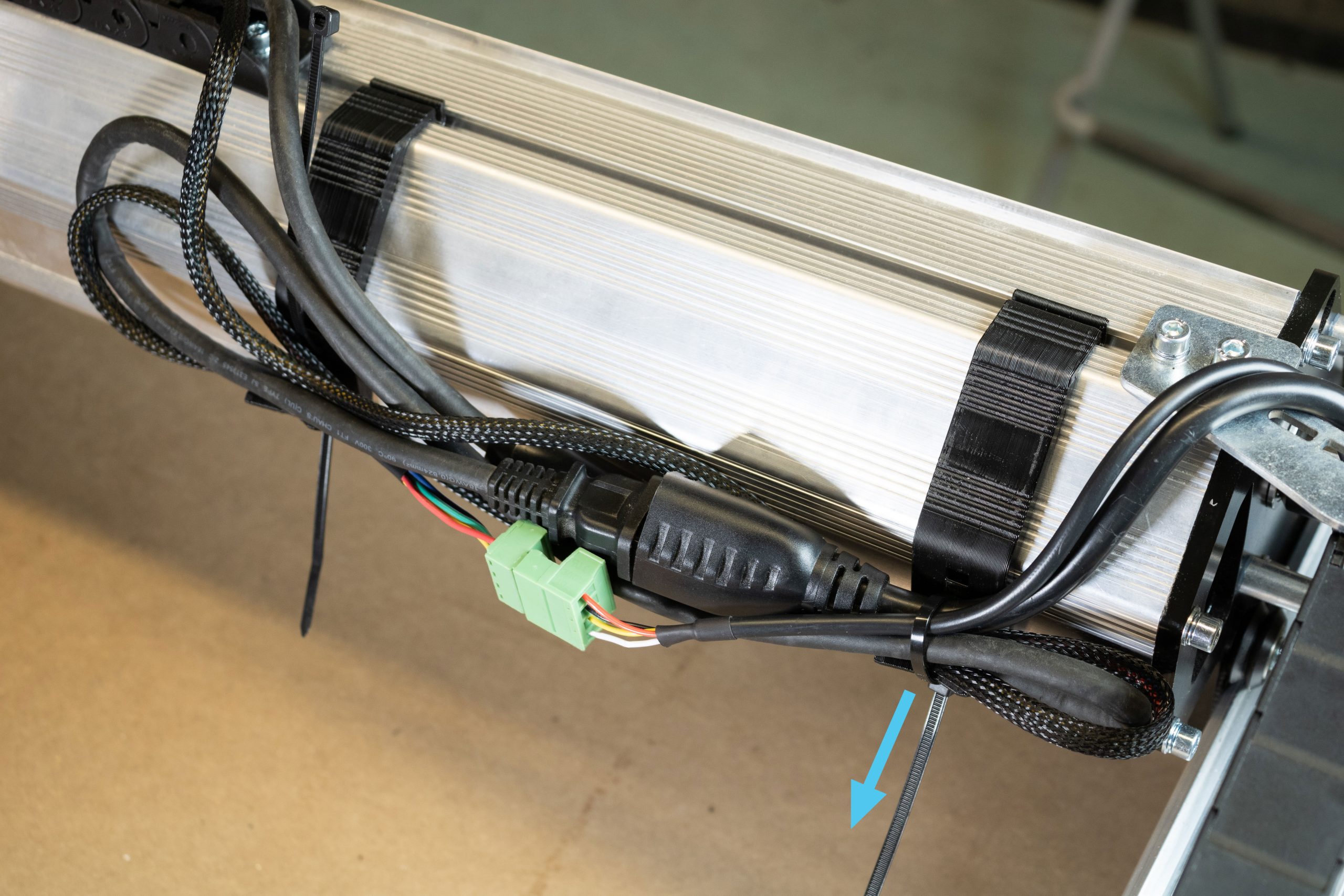
Adjust any of the cabling so it fits well within these two hangers and nothing hangs below the X-axis rail, then tighten the zip ties fully. You can adjust the position of the two cable hangers before tightening these zip ties for good. In any case, extra zip ties are provided just in case you’d like to come back and make any adjustments.
Lastly, plug in the cables for the motors on the two Y-axis NEMA 23 stepper motors.
Bring the cables around to the left of the machine so they’re now all bundled together (pictured). This is the last step specific to the 48×30 size LongMill MK2.5, you’ll be plugging the motors cables into the control box shortly but otherwise the machine wiring is now complete!
Continue to next step in main LongMill MK2.5 assembly manual