
Installation
The Inductive Sensor Kit is a plug-and-play add-on kit for your LongMill, which adds three inductive sensors to your machine to act as limit and homing switches. The kit can be ordered on our store.
Step 1: Unpacking
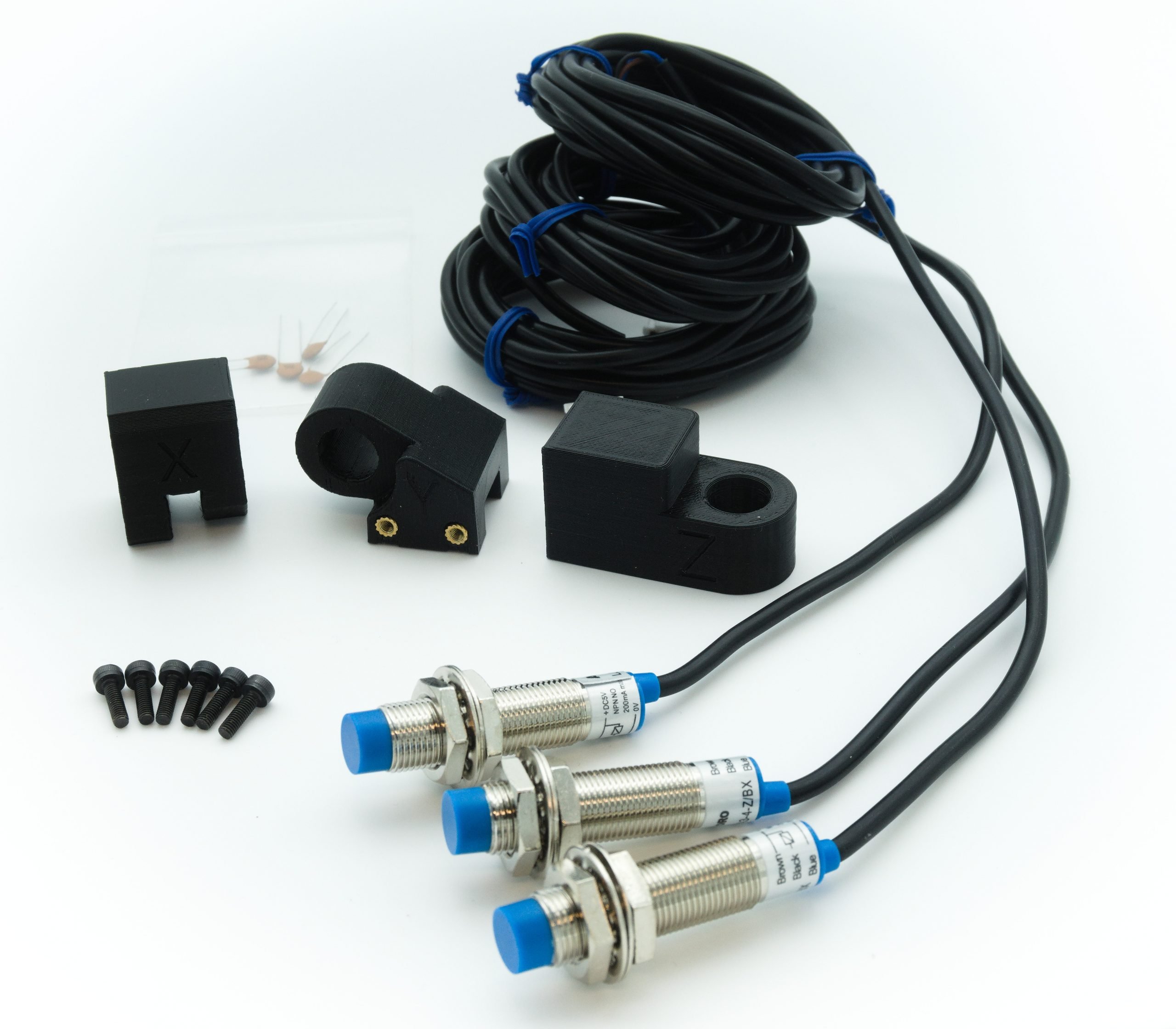
Each kit comes with:
- 10x M3-10mm socket head cap screws for mounting the brackets
- 1x X-axis mounting bracket
- 1x Y-axis mounting bracket
- 1x Z-axis mounting bracket
- 3x inductive sensors
- 3x 0.1uF – (104) ceramic capacitors*
*These capacitors are only needed for LongBoards Rev 1.1 and Rev 1.2. If your LongBoard is Rev 1.3 and above, you will not need these and they can be set aside.
You will need for installation:
- 2.5mm Allen key
- 17mm wrench or adjustable wrench*
**All kits will have the inductive sensors pre-installed, a wrench is only needed if you wish to make tweaks to the placement of the sensors themselves.
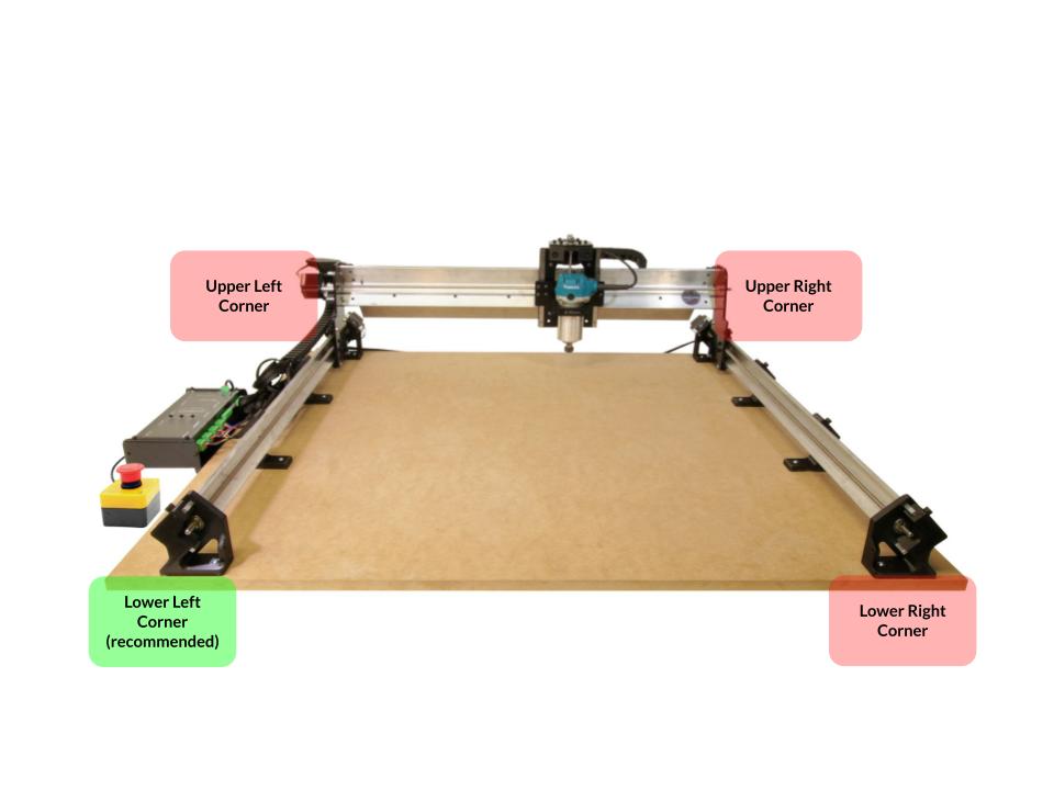
Before you begin, you can decide where to place your sensors, and which directions you would like to home the machine. You can always change this later, but by default, this guide will set up the sensors at the lower left corner.
Homing to the lower left corner is recommended because:
- This position is commonly used for your zero/origin point in projects, making it convenient for setting up jigs
- When squaring your machine by running the machine to the back, you will not run into the sensors
Step 2: Attaching to the machine
Each bracket is labelled as ‘X’, ‘Y’, or ‘Z’ so you’ll know where to mount them. You can unscrew one nut and washer off each sensor and place it in the hole of each bracket before putting the washer and nut back on, but keep them loose for now.
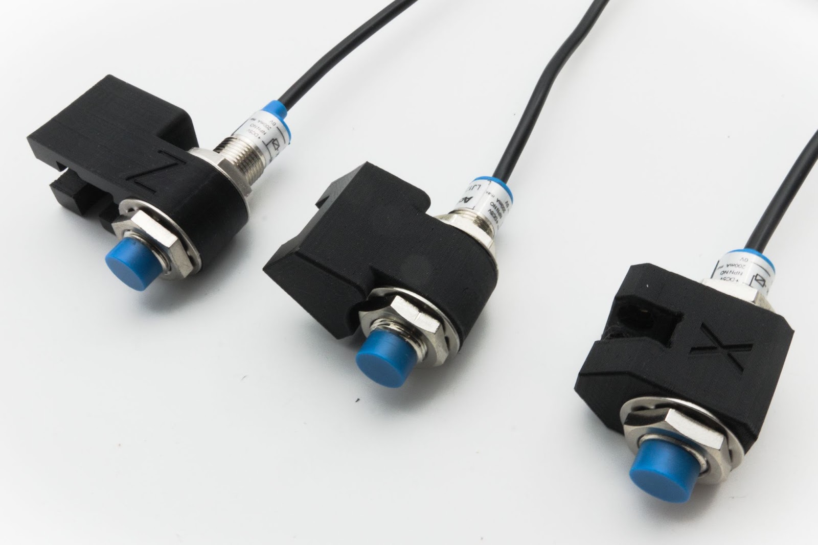
The tabs below show the attachment of limit switches for homing at the lower left corner. If you choose to home at another corner, you can rearrange the X and Y sensor mounts, mirroring what is shown below. Some positions may require you to flip the sensor.
Each bracket uses a pair of M3 screws to mount to the machine. Simply slide the bracket onto the recommended location and gently tighten the M3 screws using a 2.5mm Allen key into the brass heat-set nuts just until snug. Do not over tighten, as this could damage the bracket, but ensure that the bracket cannot move easily.
X-Axis
X-Axis Mounting
Place the X-axis sensor on the top of the left steel Y-gantry plate, sitting against the aluminum rail. The sensor should be triggered by the X-gantry plate when in contact.

X-Axis mounting with non-magnetic dust shoe
If your machine has the older-style dust shoe with aluminum extrusions and a wooden base, you will need to install the dust shoe ‘flag’ to trigger the X-axis sensor.
Loosen the smaller (M5) screw on the flag and slide the flag onto the front slot of the left aluminum extrusion as shown. Adjust the height of where the flag sits, as well as the position of the X-axis sensor on the gantry plate so that the sensor is aligned with the larger (M8) screw on the flag.

Y-Axis
Y-Axis Mounting
Slide the Y-axis sensor onto the front left 3D printed foot. The mounting tab of the sensor must line up with the edge of the extrusion, and the Y-gantry should be in the center of the mount hole.

Z-Axis
Z-Axis Mounting
Slide the Z-axis sensor mount on the top end of the left of the Z-axis, ensuring the mount is pressed against the linear guide as far as it can go. For older models (V1), you will need to remove the lower nut on the inductive sensor before the mount can be slid on. Once the mount is affixed, you can then add and tighten the sensor nut.
Depending on the machine version, you may need to adjust how far the sensor extends down. For newer models (V2-V4) with the notch at the top of the Z-axis gantry plate, the sensor sits at the upper position as shown, triggering before the M5 screw hits the ACME nut. For older models (V1) with the flat top Z-axis gantry plate, the sensor will need to be moved upwards as shown. Make sure that the sensor triggers before the machine hits the 3D printed Z-axis mount.
 and Old (Right) Limit Switch Positions")
Step 3: Adjusting the sensors on the brackets
All three inductive sensors are identical and are mounted to the brackets to allow for installation onto the machine. However, you can adjust them if you want to tweak the location of the sensors.
To adjust the position of a sensor:
- Loosen a nut and washer on one side
- Slide the sensor along the hole to the right position
- Re-tighten the loose nuts and washers to secure the sensor back in place. Note that the Z-axis sensor does not use a washer on the lower nut
Step 4: Connecting the sensors to the LongBoard controller
Unclip the tabs that hold the wires in each drag chain and route the cables from the inductive sensors. Ensure that there are no sharp bends or tears in the cables as a failed limit sensor could cause a false alarm and halt the machine during use.
- Z-axis sensor gets routed through the drag chains on the X and Y rail
- X-axis sensor gets routed through the drag chain on the Y-axis only
- Y-axis sensor does not need to be routed through a drag chain
The three cables plug into the three white JST connectors labelled as XLim, YLim, and ZLim as shown in the photo below. To make sure each of the sensors is plugged into the correct port for its axis, it is recommended to label the cable with tape and marker before routing the cables, or plug-in each cable as they are routed through the machine individually.

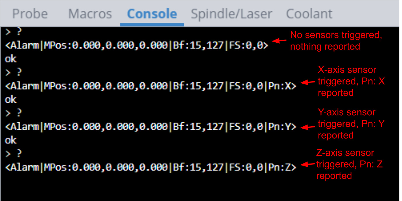
Once installed, you can verify that each sensor is working and is plugged into the correct port by using the console within UGS, gSender, or other machine interface software. Type the following command into the console: $10=19 and press enter. This will enable reporting of the current status of each of the sensors.
You can either jog the machine to trigger the sensor (shown by a red light on the sensor), or hold anything made of steel in front of the sensor. While the sensor is triggered, enter the following command into the console: ?
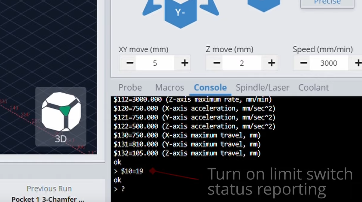
The console will now report back to you which limit sensor is triggered, indicated by an X, Y, or Z. Check this for each of the three sensors/axis to make sure the axis sensor reported matches the axis of the sensor you are manually triggering. If the reported triggered sensor does not match the sensor you are triggering, swap the cable plugs at the board as necessary so they all match. This can also be very useful for diagnosing issues with your sensors.
After you’ve finished checking that each sensor is reporting correctly, you can set disable sensor status reporting by setting the default value: $10=3
Adding capacitors for LongBoard revision 1.2
Look on the top of your LongBoard to see the revision number just below the Sienci Labs logo. LongBoard revisions 1.3 and 1.4 come preinstalled with capacitors for each of the limit switch circuits. If your board is revision 1.3 or 1.4, you can set aside the included capacitors and skip to Step 5. If your LongBoard is revision 1.2, however, it does not come pre-installed with capacitors and may be subject to triggering falsely due to electrical noise. Therefore, each kit includes a set of 0.1 mF ceramic non-polarized capacitors to filter out any electrical noise. The capacitors used are shown below.
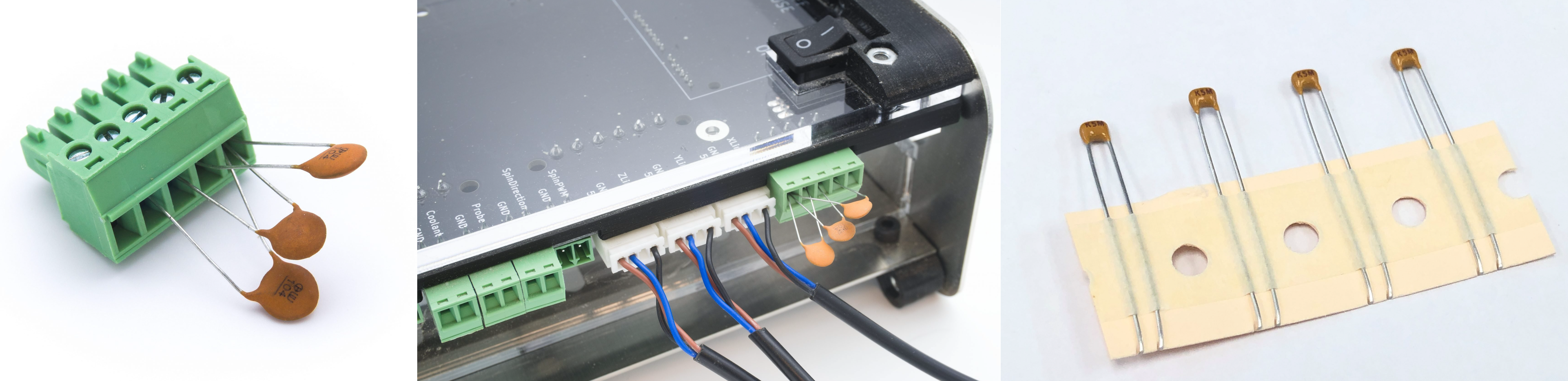
Remove the green 5 port connector installed in the ‘5V, Xlim, Ylim, Zlim, GND’ port on the LongBoard. Then loosen the screw terminals of the connector and insert three capacitors into the connector as shown in the photo above. For each capacitor, one prong should be inserted to the GND port, and one prong into the X, Y, or Z port. Re-tighten each of the screw terminals on the connector then plug the connector back into the secondary limit switch port.
Plug in the X, Y, and Z-axis limit switch connectors into each of the three white connectors as shown in the photo above.
Step 5: Changing your settings for limit switches
If you received your machine before September 2021, you may need to update your LongMill’s firmware to the latest version to have access to all of the updates for your limit switches to work. At the time of writing, the latest version of the LongMill firmware is Sept 8, 2021.
To update your firmware, connect your machine to gSender and:
Current
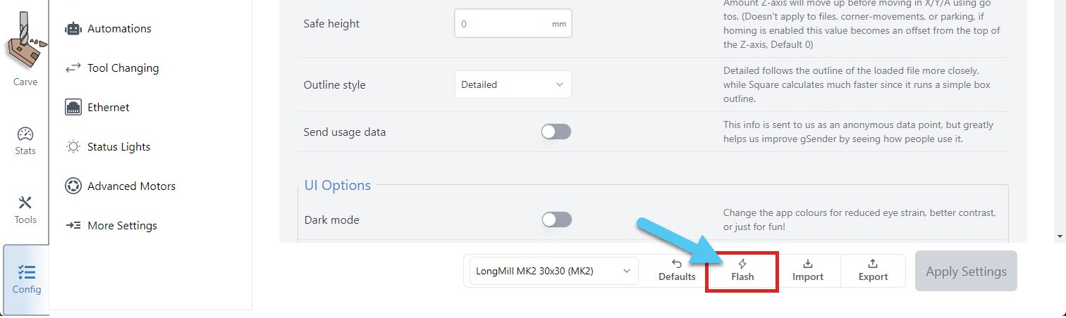
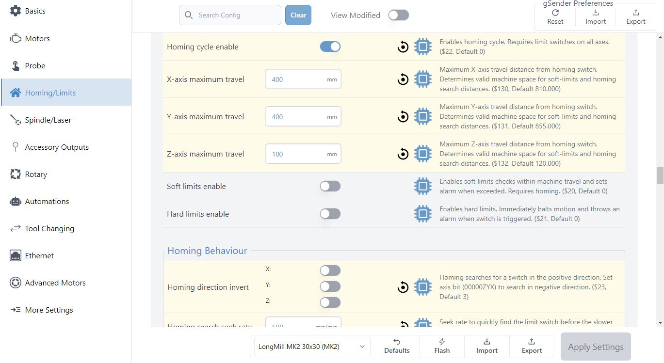
To update your firmware, connect your machine to gSender, click on the Config tab, and click on the Flash button. Follow the prompts to install the latest version of the firmware onto your LongBoard.
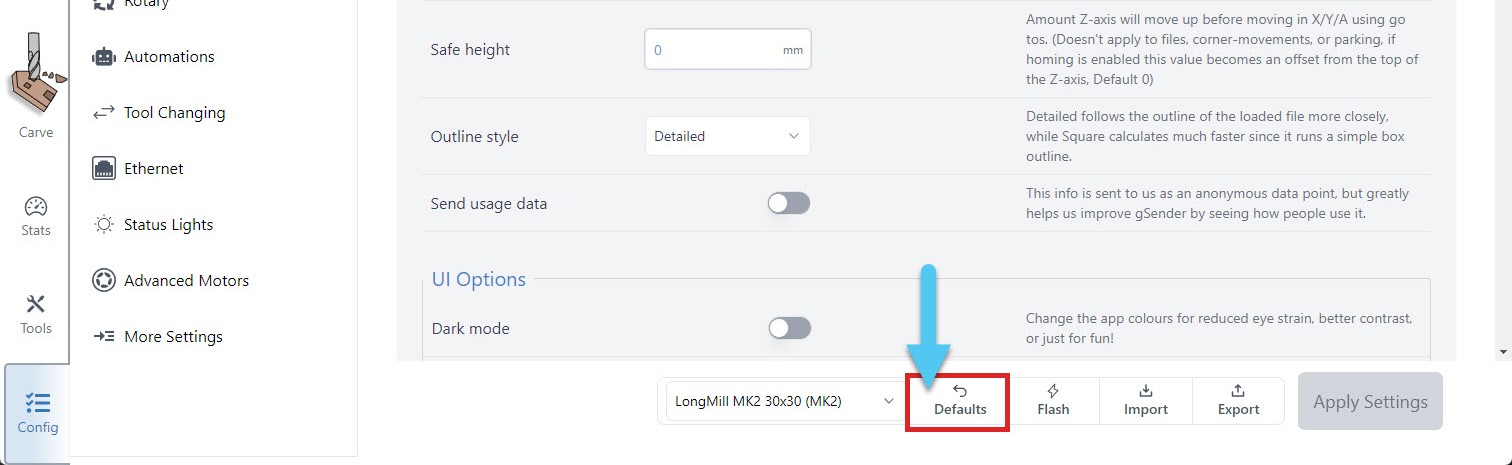
Next, import our default settings for your machine by pressing the Defaults button in the Config tab and confirming the update. If you wish to make changes or adjustments, additional info about changing your EEPROM settings can be found further down on this page.
Classic gSender
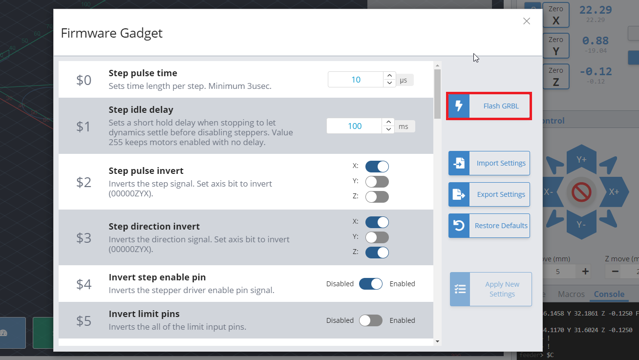
To update your firmware, connect your machine to gSender, click on “Firmware”, and click on the “Flash grbl” button. Follow the prompts to install the latest version of the firmware onto your LongBoard.
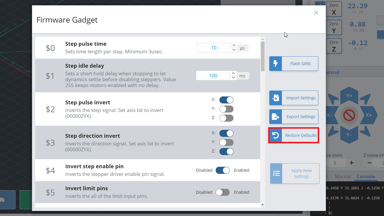
Next, import our default settings for your machine by pressing the “Restore Defaults” button in the “Firmware” window. Use the “Import Settings” tool and update your EEPROM settings to the new defaults (link to download file coming soon). If you wish to make changes or adjustments, additional info about changing your EEPROM settings can be found further down on this page.
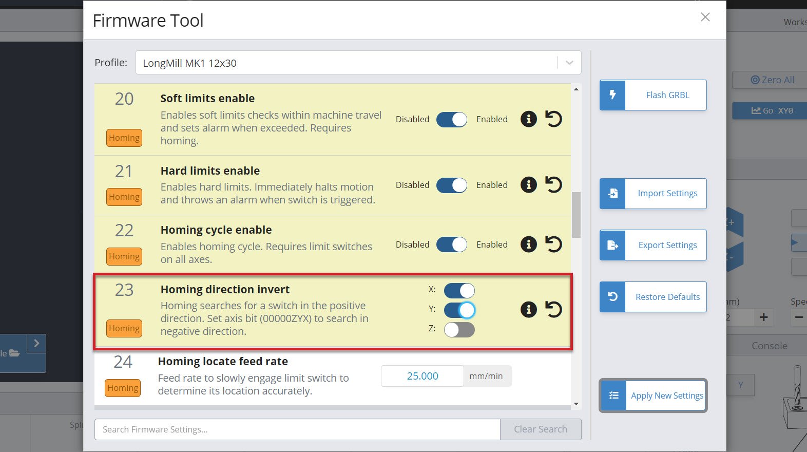
Recommended settings for sensors
Now that we’re working with the default settings, we will modify a few to make them work with the sensors.
- Enable Soft and Hard limits ($20 and $21)
- Enable Homing cycle ($22)
- Check Homing direction invert ($23)
- Check X and Y-axis travel limits ($130 and $131)

Soft limits and Hard limits
Both soft limits and hard limits will stop the machine if it is moving to the boundaries of the machine. Soft limits determines when to stop using calculations in the software program, NOT by triggers at the sensor. Hard limits determines when to stop from the trigger of the sensors.
We recommend using both, so that one end of the machine is constrained by hard limits (bottom and left directions) and the other end is constrained by soft limits. You may get error messages if you are trying to move past the boundaries. If so, try jogging the machine away from machine boundaries, or jog at a smaller distance when near boundaries.
Homing cycle
By enabling the homing cycle, you are able to home your machine with the sensors. So each time you connect to gSender, it will prompt you to home your machine (showing a red alarm). This is a safety feature, to check that the sensors are working and to ensure your machine will move within bounds. You can click on the lock icon in the top left corner to unlock your machine and skip this step if you wish.
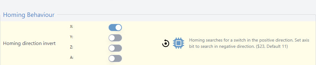
Homing direction
If you want to set your home at the front left corner and have installed your inductive sensors to match, you will need to invert your X and Y-axis. By default all axes will home in the “positive” direction which is typically Right (X), Away (Y), and Up (Z) so toggle these as needed for your setup.
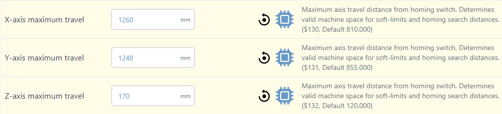
X and Y travel limits
We recommend that $130=750 and $131=810 on your firmware settings for a LongMill 30×30. These numbers are used by the soft limits to stop your CNC from crashing into itself so they’ll be different based on your CNC setup and if you use accessories that get in the way.
If you need to find the maximum travel for your unique setup do the following (optional); home your machine, zero all axes, then jog each axis to where you feel comfortable limiting it. Use the coordinates to set your maximum travel for each axis.

Step 6: Using your sensors
At this stage, you’re ready to start using your sensors.
Testing limit switches
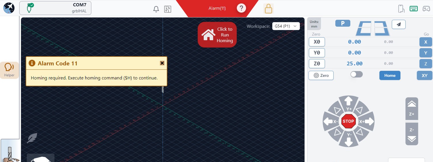
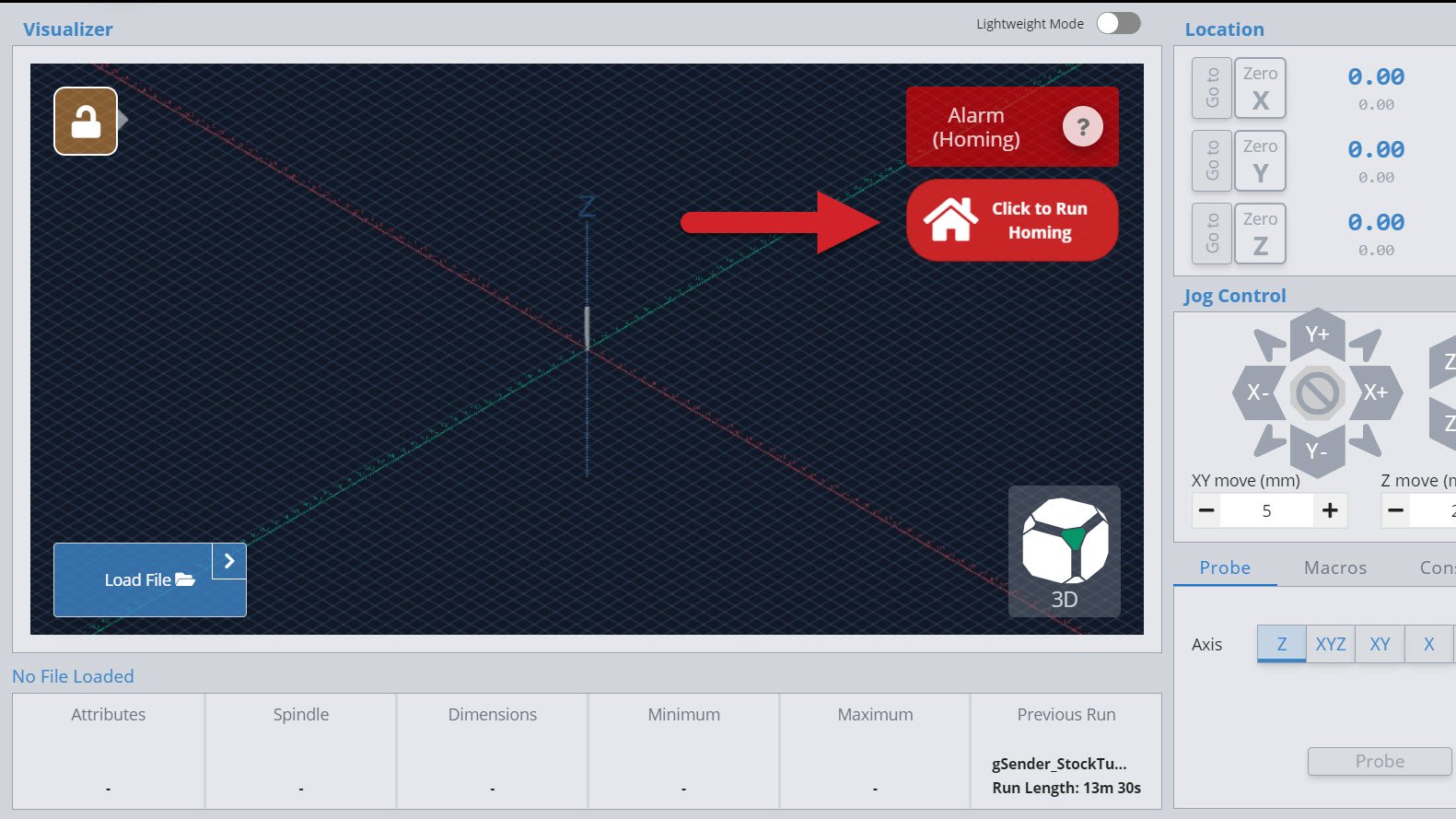
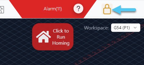
Once the firmware changes have been made, test the sensors. Disconnect, then reconnect to your machine. You should see the red alarm at the top right, press “Click to Run Homing.”
On gSender, the process for limit switch homing is very similar to touch plate probing. This is what happens on the LongMill when you run the homing cycle:
- Machine moves up quickly in the Z-axis, until the switch gets triggered
- Machine retracts slightly, moves up slowly in the Z-axis, until switch gets triggered again
- Machine quickly moves diagonally across table to upper right corner, until the switch gets triggered
- Machine retracts slightly, slowly moves diagonally across table to upper right corner, until switch gets triggered again
If this process completes without any errors, you have successfully homed your machine!
Homing features
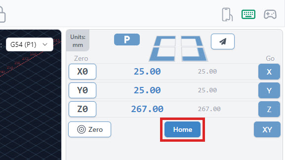
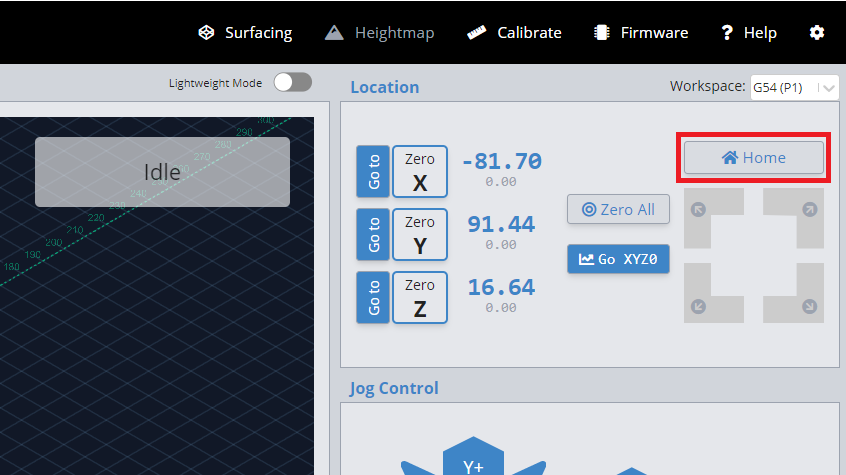
Once you have connected to your machine, at any point when you aren’t running a cutting job, you can run the homing cycle by pressing “Home” with the house icon.
Current
Additionally, if you first connect and need to bypass the alarm without homing, you can by pressing the “Unlock” yellow padlock button on the top right of the visualizer screen. We do not recommend this usually, because it is safer to home first before running a cutting job.
Classic gSender
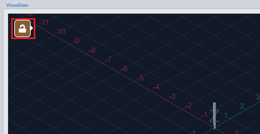
Additionally, if you first connect and need to bypass the alarm without homing, you can by pressing the “Unlock” yellow padlock button on the top left of the visualizer screen. We do not recommend this usually, because it is safer to home first before running a cutting job.
Work offsets
With CNC, work offsets can be thought of as bookmarks. They are saved origin positions on your machine that allow you to always return later to a known location. Having one or more known locations you can repeatedly return to is extremely useful for many reasons such as:
- Restarting a failed job
- Recovering from a power outage during a job
- Repeating a job in a fixture or multiple fixtures
- Returning to an exact work XY origin after performing a tool change
The repeatability of the inductive limit switches has been tested to be less than 0.001″, meaning that you will always be able to return to your original work origin within 0.001″ accuracy, and can confidently repeat jobs without worries of toolpath misalignment or crashes.
To change work offsets or workspaces, simply select one of the 6 workspaces from the drop-down list in the top right corner of gSender as shown in the photo below.


Alternatively, entering the command G54, G55, G56.. etc. into the console of gSender or UGS will tell the machine to switch into that workspace. You will notice the work coordinates (blue numbers) will change upon switching workspaces to whatever the coordinates are within the new workspace. The machine coordinates (grey numbers) will always remain the same regardless, as these are of course relative to your machine’s home position.
All 6 of these workspaces are modal settings, meaning they will be saved by the controller even after powering off the machine.
Other Limit Switch Settings
Homing locate feed rate ($24)
By default, this speed is set to $24=25, which sets the homing locate feed rate to 25 mm/min. When homing your machine, the machine will first move at a preset speed (see $25 – Homing Seek) to more rapidly reach the limit switch, move away from the switch to deactivate it, then move towards the limit switch at a slower speed for a more accurate reading. We recommend keeping this value at 25mm/min as it works for most limit switches.
Homing seek ($25)
By default, this speed is set to $25=500, which sets the homing search seek rate to 500 mm/min. This is the speed of which the machine will move to locate each limit switch.
Homing switch debounce delay ($26)
By default, this time is set to $26=250, which controls the delay before the controller measures if the signal is on or off. Some switches can take a few moments before an on or off signal is defined. We recommend keeping this at its default setting. However, if you find that your switch randomly triggers for no reason, you may want to increase the debounce delay.
Homing pull-off distance ($27)
By default, this distance is set to $27=1. This distance determines the distance that the machine needs to move away from the switch to un-trigger it. For some sensors, such as mechanical switches, this can be a few millimetres, while for inductive proximity sensors may only need a fraction of a millimetre. For inductive sensors, we recommend keeping your default homing pull off distance at 1mm, while if you are using mechanical switches, to use a large number to ensure that your switch is completely untriggered after your homing sequence.