
Standard Block-Style Plate
Setting up any style of touch plate on your LongMill is easy. Since it only requires a ‘closed’ connection between two wires you can use all sorts of plate designs from a thin metal sheet to a more common block style to probing off the material itself if it’s conductive. Once wired, the last step is to check that your g-code sender understands the shape of your touch plate and how you plan to use it.
All the touch plates that we provide have instructions below and are fully supported by gSender as well as have some support for other popular senders like UGS, CNCjs, and more.
This guide covers set up and use of our Standard Touch Plate. If you have a different or custom touch plate that’s a block shape these steps can also be applied for software setup and usage.
Inside the package:
- Block-style touch plate
- Cable with a banana plug and magnet (~1.8m)
Wiring
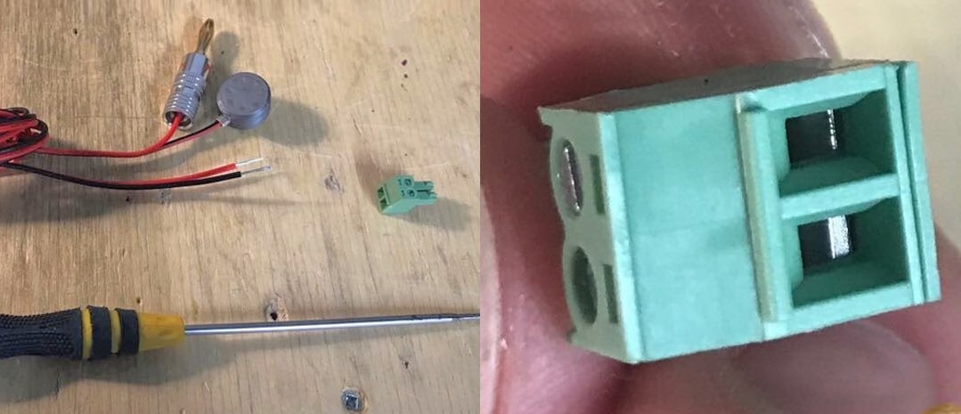
Our touch plates come mostly pre-wired but sometimes a green connector will need to be attached. If your wire harness doesn’t have a green connector attached already, look for it to be plugged into the Probe and GND pin pair on your LongMill control board. These terminal connectors have a built-in clamping system that you can open and close by turning the flat head screw at the top of each connection point.
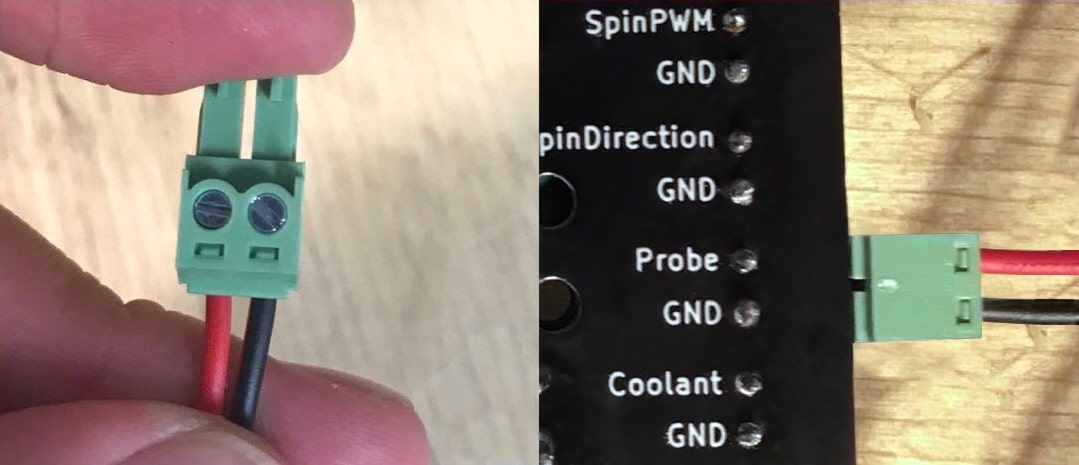
Use a flat head screwdriver to clamp down on the exposed wire ends from the harness ensuring the red and black wires are in the correct order as in the photo. You can check for a reliable connection by giving the wires a small tug and they’ll feel firmly clamped in place. Plug the connector back into the board once finished.
At the other end of the wiring harness will be a magnet and a banana plug. The touch plate has two different holes to insert the banana plug so you can choose the hole that keeps wiring tidy for your setup. Make sure you push it in all the way; the connection should feel snug.
To help you visualize the final setup in action: when you go to probe you’ll attach the magnet to your router collet or directly to the cutting tool, place the touch plate on your material, then run the probing operation where the tool will touch the plate and make a closed ‘circuit’ to sense it. When you do this, ensure your tool is firmly secured in the collet and is also sticking out at least 15 to 20mm so it can make good contact with the plate. For other notes on tool compatibility, see more at the end of this guide.
Software Configuration
With wiring complete, let’s move on to setting up your g-code sender to work with the touch plate. gSender and UGS (UGSPlatform) are easiest to configure for this style probe so we’ll show setup for both below.
Current
gSender comes pre-loaded with all the settings needed for our touch plate and is able probe easily in the X, Y, and Z-axis and some other combinations.
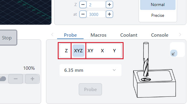
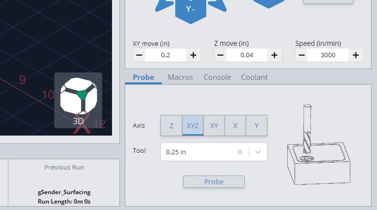
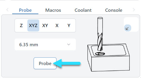
All probing happens in the Probe tab on the main Carve screen. Here you can select what type of probing you’d like to perform as well as select the tool you’ll be using or you can type in the tool size manually.
- Z: Finds the Z height only.
- XYZ: Finds the zero point on the front, left corner of your material in all axes.
- XY, X, Y: Finds the zero point in the X and/or Y directions only.
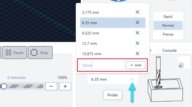
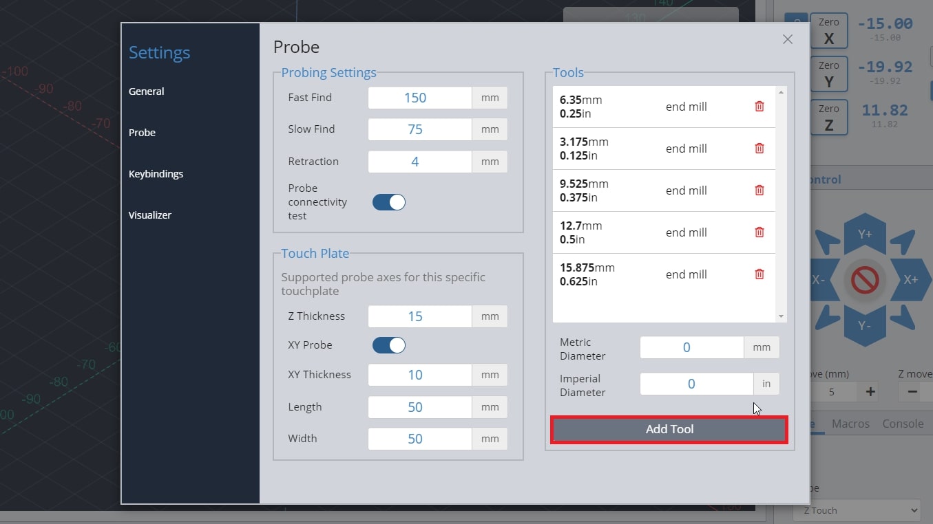
You can also add tools here if you want the probe widget to remember your most commonly used tools.
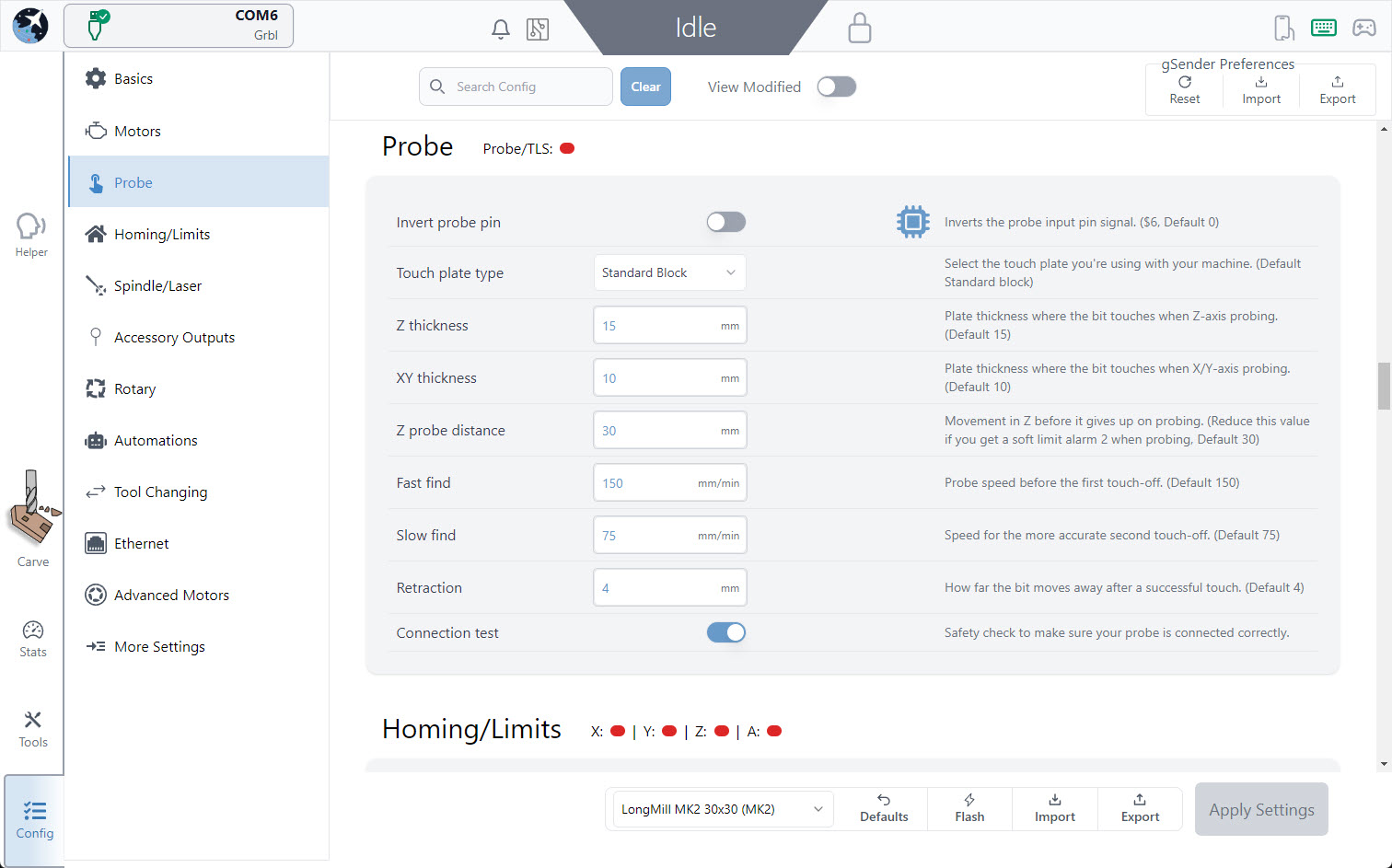
If you have a third-party touch plate, you can click on the Config tab and then select or scroll to the Probe section. Here you’ll be able to customize your plate dimensions, the probing speed, or switch over to a Z-only probe.
Classic gSender
gSender comes pre-loaded with all the settings needed for our touch plate and is able probe easily in the X, Y, and Z-axis and some other combinations.
All probing happens in the Probe tab in the main window. Here you can select what type of probing you’d like to perform as well as select the tool you’ll be using or you can type in the tool size manually.
- Z: Finds the Z height only.
- XYZ: Finds the zero point on the front, left corner of your material in all axes.
- XY, X, Y: Finds the zero point in the X and/or Y directions only.
If you have a third-party touch plate, you can press the gear icon at the top right of the window to access the settings, which will pop up a window. Go to the ‘Probe’ settings on the left hand side. Here you’ll be able to customize your plate dimensions, the probing speed, or switch over to a Z-only probe.
You can also add tools here if you want the probe widget to remember your most commonly used tools.
UGS
UGS comes with a simple plugin that allows for your machine to send the commands to your machine to utilize the touch plate for finding the X, Y, and Z-axis.
Start by going to the top of your screen and clicking Window ➜ Plugin ➜ Probe Module. You will see a new tab appear on your screen.
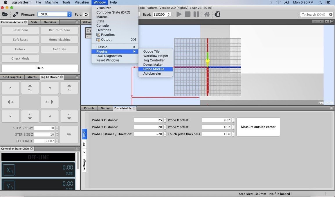
Next, we will change a few settings. Click on the “Settings” button on the plugin.
- Units: choose between millimeters and inches. For this guide, we will be using millimeters.
- End Mill Diameter: the diameter of the end mill you will be using. You can find this diameter based on your manufacturer’s specs, or you can measure it yourself.
- Fast Find Rate: the speed the machine will move to touch off the touch plate on the first pass. Set this to 150.
- Slow Find Rate: the speed the machine will move to touch off the touch plate on the second pass. Set this to 25.
- Retract Amount: how far your tool moves away from the touch plate on its first touch off. Keep this setting at 1.
Within the left side of the plugin, you’ll also see a few more tabs
- XYZ: Finds the origin/datum point on the corner of your material in all axes.
- XY: Finds the origin/datum point in the X and Y direction only.
- Z: Finds the Z height only.
In these sections, makes sure that these settings are changed. If your section does not have that setting available to change, you can skip it. This means that in the XYZ tab you’ll enter all these settings, in the XY tab you’ll only use the settings pertaining to the x and y-directions, and in the Z tab you’ll only use the settings pertaining to the z-direction.
- Probe X Distance: 25
- Probe Y Distance: 25
- Probe X Offset: 10
- Probe Y Offset: 10
- Probe Distance/Direction: -15 (make sure this value is negative)
- Touch Plate Thickness: 15
Using your Touch Plate
We’re pretty much ready to go!
If you want to run a probing operation, first we need to place the touch plate and set up the magnet. There needs to always be an electrical connection between the block and magnet for probing to work. gSender has a feature to check this for you, meanwhile UGS you’ll need to do this manually.
- Make sure the magnet is attached to the collet nut of the Makita router.
- For XYZ probing:
- Place the touch plate on the front left corner of your material. Make sure that both of the inner faces of the touch plate are contacting the edges of your material.
- Jog your machine to position the cutting tool about 10mm (½”) or closer above the circular logo on the touch plate.

Current
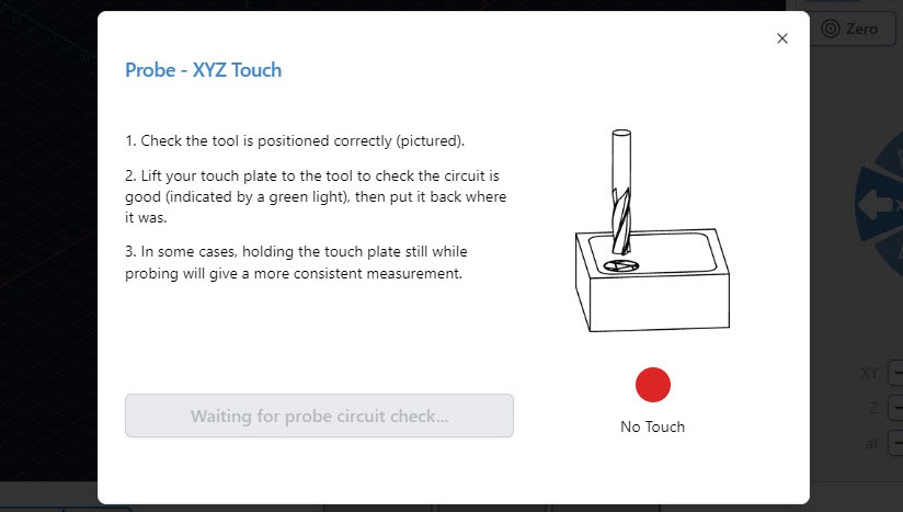
Back in the ‘Probe’ tab, you can choose which axis to probe for and the diameter of the bit you’re using – in this case select ‘XYZ’. The bit size can be selected from the drop-down of saved bits, or can be typed in manually. Press the ‘Probe’ button and you’ll get a pop-up window to confirm you’ve positioned your bit correctly and you’ll be prompted to check for a good connection.
You can either bring the touch plate to the end mill or touch the banana plug and magnet together. Make contact a few times just to confirm there is conductivity, as the red circle should flicker to green and a blue ‘Start Probe’ button appears.
Pressing ‘Start Probe’ will now make the machine move to probe three sides of the touch plate, twice on each side. There should not be any crashing or abrupt movement. Once the process is over, remove the touch plate components from the machine then press the blue ‘XY’ button in the Go column. The bit should be over-top of the bottom left corner of the stock material, and pressing the blue ‘Z’ Button in the Go column should bring it to touch the materials surface.
If the probing was unsuccessful, then it’ll be indicated by the cutting bit not returning to where you started the probe cycle or the machine will be put into an ‘ALARM’ state. To bring it out of the alarm state, press the pulsing ‘Unlock’ button in the middle of the visualizer and that will put the machine back into its ‘IDLE’ state. An unsuccessful probing cycle can result from an incorrectly positioned probe or starting too far outside the circular logo. Be sure to verify your setup before attempting another probing cycle.
Classic gSender
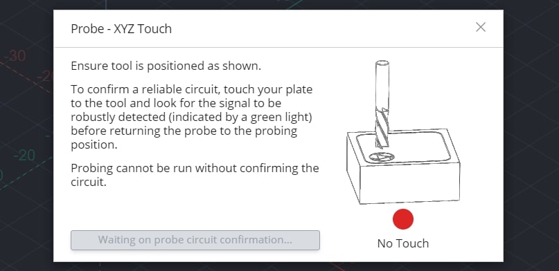
Back in the ‘Probe’ tab, you can choose which axis to probe for and the diameter of the bit you’re using – in this case select ‘XYZ’. The bit size can be selected from the drop-down of saved bits, or can be typed in manually. Press the ‘Probe’ button and you’ll get a pop-up window to confirm you’ve positioned your bit correctly and you’ll be prompted to check for a good connection.
You can either bring the touch plate to the end mill or touch the banana plug and magnet together. Make contact a few times just to confirm there is conductivity, as the red circle should flicker to green and a blue ‘Start Probe’ button appears.
Pressing ‘Start Probe’ will now make the machine move to probe three sides of the touch plate, twice on each side. There should not be any crashing or abrupt movement. Once the process is over, remove the touch plate components from the machine and then press ‘Go to XY0’. The bit should be over-top of the bottom left corner of the stock material, and pressing ‘Go to’ next to the ‘Zero Z’ should bring it to touch the materials surface.
If the probing was unsuccessful, then it’ll be indicated by the cutting bit not returning to where you started the probe cycle or the machine will be put into an ‘ALARM’ state. To bring it out of the alarm state, press the pulsing ‘Unlock’ button in the middle of the visualizer and that will put the machine back into its ‘IDLE’ state. An unsuccessful probing cycle can result from an incorrectly positioned probe or starting too far outside the circular logo. Be sure to verify your setup before attempting another probing cycle.
UGS
Open up the probing window in UGS and in the XYZ tab press “Measure outside corner”. The LongMill will go through a cycle to probe and take its measurements.
If the probing function is successful, then the machine should return the bit back to the starting point where you initiated the probing cycle. You should notice that the ‘DRO’ (Digital Read Out) on UGSPlatform changes to reflect the measurements, the current position being offset a little in the X and Y and quite a bit offset in the Z.
You can check that it’s now zeroed on the material corner by first taking the touch plate off the material and removing the magnet from the router collet before pressing “Return to Zero”.
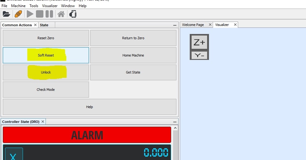
If the probing was unsuccessful, then it’ll be indicated by the cutting bit not returning to where you started the probe cycle or the machine will be put into an ‘ALARM’ state. To bring it out of the alarm state, press the “Soft Reset” button followed by the “Unlock” button and that will put the machine back into its ‘IDLE’ state. An unsuccessful probing cycle can result from an incorrectly positioned probe, the magnet not attached to the collet properly, starting too far outside the circular logo, and the probe not being plugged into the controller. Be sure to verify your setup before attempting another probing cycle.
If everything went according to plan, you should now see your bit hovering at the material corner like this:
Remove your magnet and set your touch plate aside, and you’re done!
Here are some other options you can use when probing:
- For just finding the top of your material (Z):
- Flip your touch plate upside down and place it on top of the material that you want to find the top of.
- Position the cutting tool so that it’s above the indented part of the touch plate.
- For XY probing:
- Place the touch plate on the front left corner of your material. Make sure that both of the inner faces of the touch plate are contacting the edges of your material.
- Jog your machine to position the cutting tool at the outer corner of the plate, lowered down from its top surface.
- For X and Y probing:
- Place the touch plate on the front left corner of your material. Make sure that both of the inner faces of the touch plate are contacting the edges of your material.
- Jog your machine to position the cutting tool away from the X or Y face.

Concluding notes:
You may have some issues with using your touch probe if your cutting tool is:
- Irregularly shaped (v bits, dado bits) and the side of the widest point of the bit does not touch off on the side of the touch plate
- Non-conductive
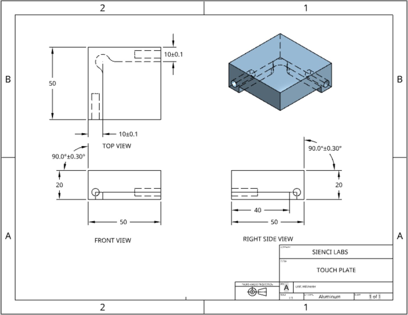
- You’ve entered the incorrect plate dimensions. You can refer to our own design below or the dimensions supplied by your third-party touch plate manufacturer:
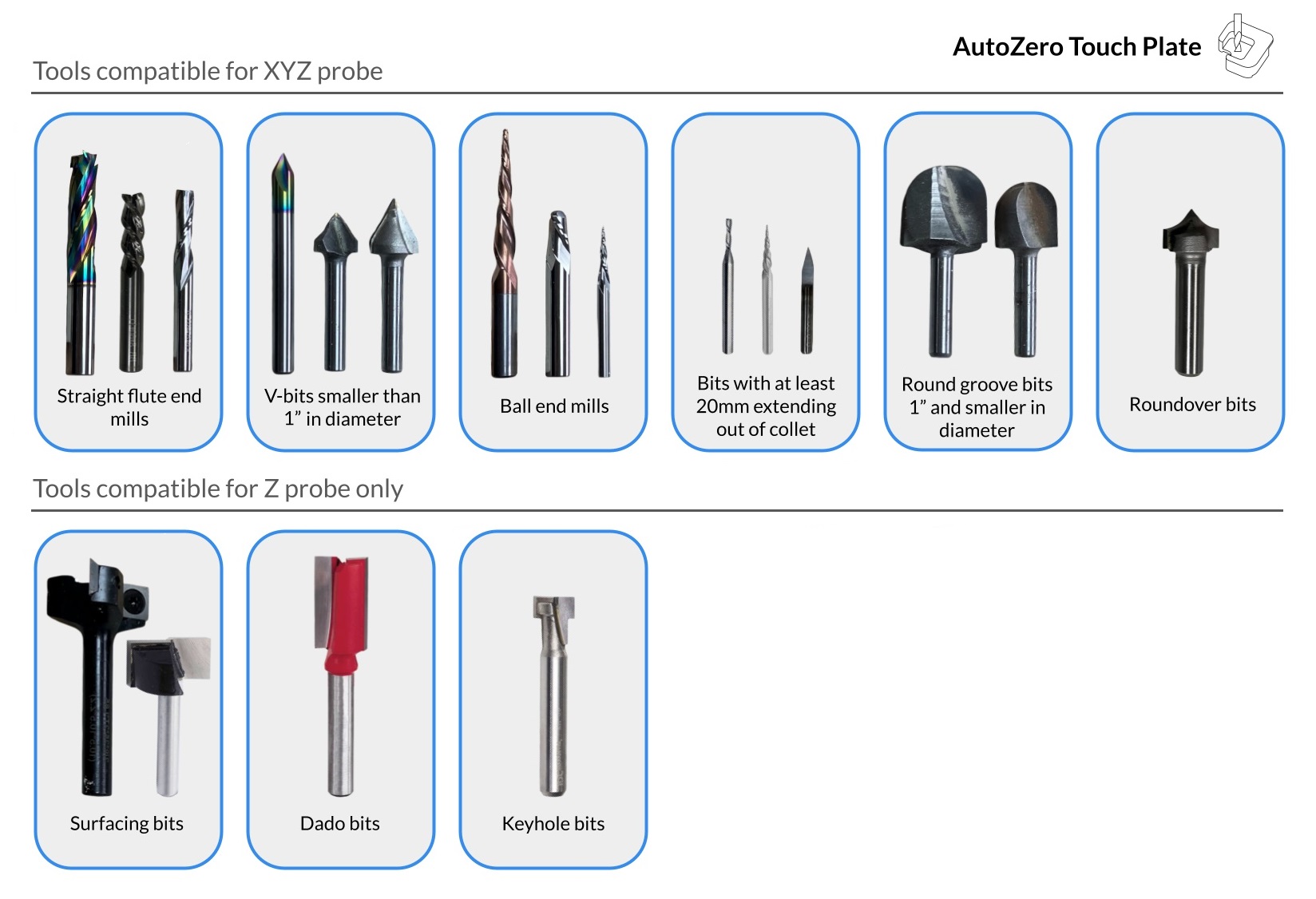
AutoZero Touch Plate
The AutoZero Touch Plate is specifically designed for use with the latest version of gSender. Please download the latest program first.
Step 1: Unwrapping and setting up your touch plate
Each order for the AutoZero Touch Plate comes with:
- The AutoZero Touch Plate itself and
- A cable that has a green connector on one end and a magnet and banana plug on the other
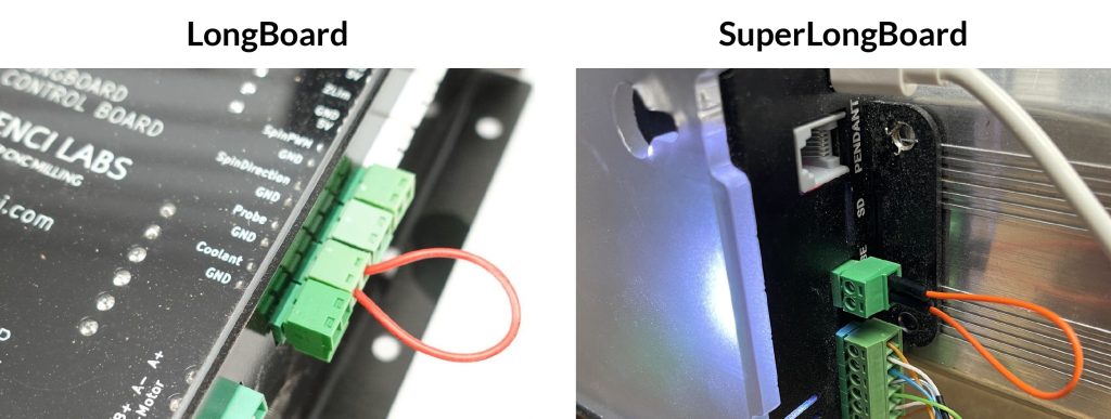
If your cable didn’t come with a green connector, you should find a spare one came with your board in a baggy or plugged into the board already (look for the writing “PRB” or “Probe”). These connectors are called 3.81mm pluggable screw terminals and can have wires attached to them using a regular, small flat head screwdriver. When you do this the wire order doesn’t matter.
Step 2: Update your gSender settings
All probing macros for the AutoZero are built into gSender making it easy to set up.
Current
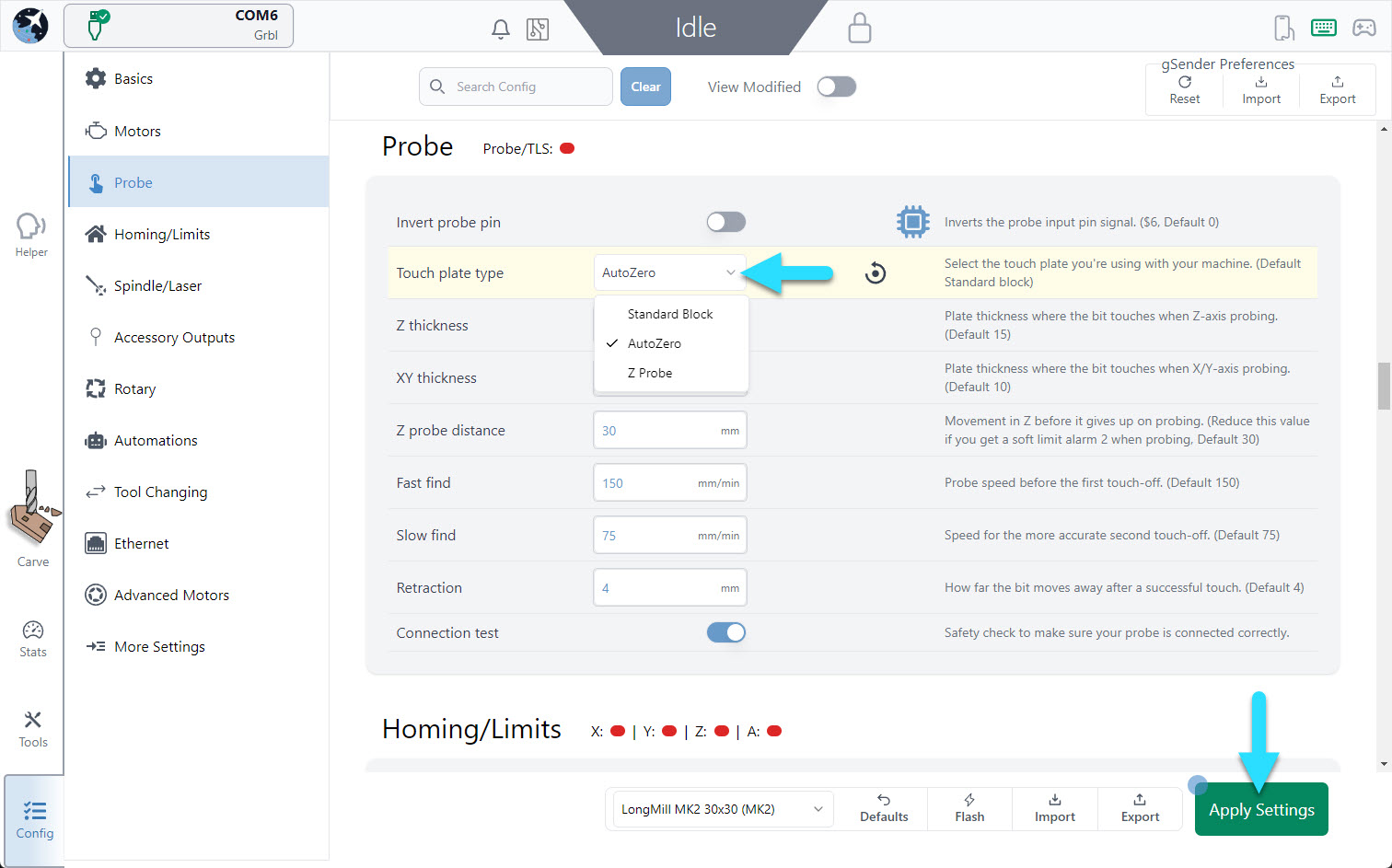
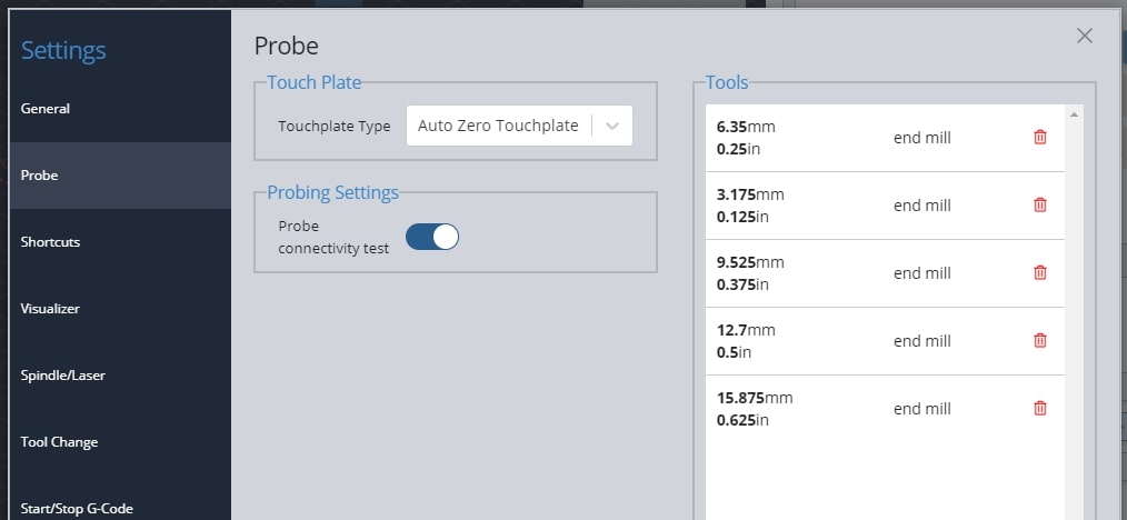
The key step is to make sure to go to gSenders settings (Config tab in the bottom left) ➜ go to the ‘Probe’ settings ➜ and change the touch plate type to “AutoZero Touch plate” in the dropdown menu. If you don’t do this, or at a later time you find the probing macros are moving strangely, then you should come back to check that this setting is still correct. Remember to hit the Apply Settings button once you’ve changed your touch plate type.
We recommend leaving the “Connection Test” option activated as well. If you’re not using gSender and have the AutoZero, we also provide macros for other common senders.
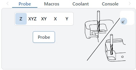
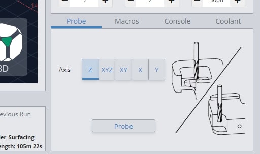
Your Probe tab at the bottom right side of the Carve screen should now update to show images of the AutoZero. These tell you how you should position your bit if you’d like to perform probing for that axis.
Classic gSender
The key step is to make sure to go to gSenders settings (gear icon at the top, right of the window) ➜ go to the ‘Probe’ settings ➜ and change the touch plate type to “AutoZero Touch plate” in the dropdown menu. If you don’t do this, or at a later time you find the probing macros are moving strangely, then you should come back to check that this setting is still correct.
We recommend leaving the “Probe Connectivity Test” option activated as well. If you’re not using gSender and have the AutoZero, we also provide macros for other common senders.
Your Probe tab at the bottom right side of the screen should now update to show images of the AutoZero. These tell you how you should position your bit if you’d like to perform probing for that axis.
Step 3: Setting up the touch plate on your workpiece
The AutoZero can find the X, Y, and Z coordinates on rectangular pieces of material. The material should be square and flat to get the best reading. The AutoZero can also find the Z-height of most flat materials as well regardless of their shape.
- Start off by plugging the green pluggable terminal into the controller. Make sure that it is in the PROBE/GND terminal.
- Next, plug the banana plug into the touch plate. There are two holes, either of which can be used to your preference.
- For any probing with X or Y, you’ll need to set the block at the bottom left corner of your material. The inside edge of the bottom of the touch plate should be touching against the sides of the material.
- If you are probing just the Z-axis, you can still place the probe on the corner normally or alternately flip it over and place it on the surface of the material to use the back ‘tab’.
Step 4: Probing
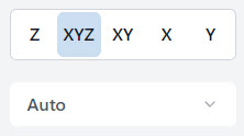
The AutoZero can probe in all three axes. The type of probing can be selected with one of the five options on the interface. The selection determines which axis the machine will be probing for and which coordinates it will reset once the probing cycle is complete.
Before you begin, make sure that both the touch plate is connected and the magnet is connected to the end mill or a nearby conductive surface such as the shank of the router or the router nut. gSender will ask to check for the continuity of the plate before starting the process to ensure your probe has the proper connection by asking you to touch the plate to your bit.
For the “Z” Axis probe, the machine will move down and touch off the block to find the offset distance based on the touch plate’s thickness. Set the end mill above the back lip of the touch plate which is designed for doing Z probes.
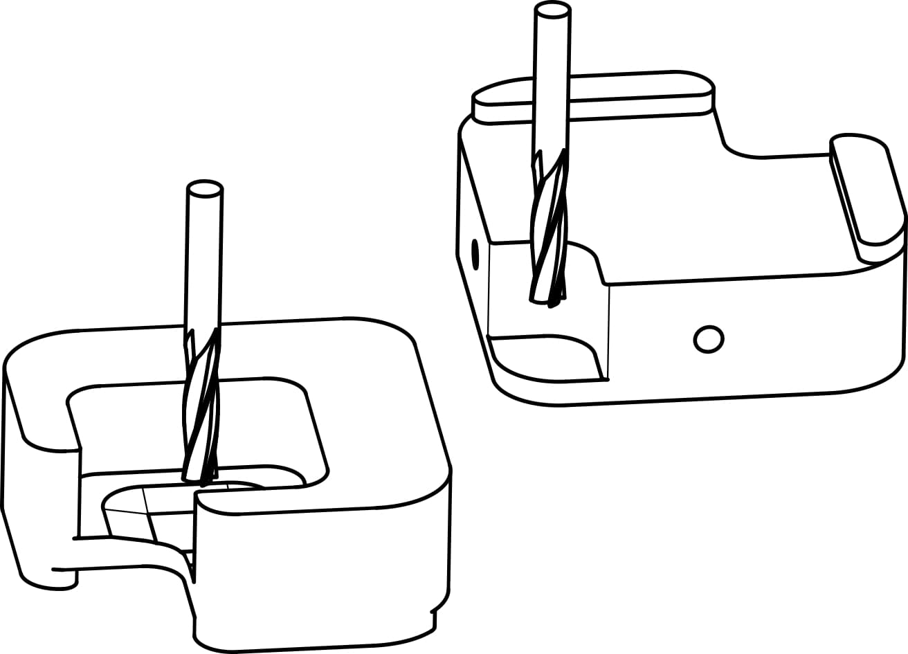
For all other probing (XYZ etc…), jog the machine over the inner square before starting the process. Your end mill should be above the square so that when the machine starts to move down, the first surface your bit touches is that square.
During the probing process, the touch plate may slide during the touch off process. It is recommended to keep a hand against the plate to prevent it from sliding around being careful that your hand isn’t in the way of the end mill.
You’ll also have the option for choosing which tool you’re using, either “Auto” or “Tip”. Auto measures the diameter on straight end mills and bits. On the other hand, Tip uses the tip of v-bits, tapered bits, and ball nose bits touching against the bottom chamfer to determine its position. Using the correct setting will ensure the most accurate probing for your bit.
Finally, click on the probe to check the continuity and start the probing process.

Note: Nearly all cutting tools have been tested to work with the AutoZero, but it’s still possible to find exceptions since bits come in all shapes and sizes. Some would include:
- Large, irregularly shaped surfacing bits that can’t fit inside the AutoZero for XY probing
- Though Z probing with the plate flipped over should still work
- End mills that are flat bottomed and short, or adapt from a large shaft to a smaller cutting diameter (for instance 1/8″ shaft to 1/16″ cutting diameter)
- These can still work as long as the overall bit sticks out far enough (over 20mm) from the collet – it will look weird when it probes because probing in X and Y might touch the shaft instead of the cutting geometry, but as long as you’re using Auto or you’ve specified the shaft diameter manually then the probing should still complete fine
Step 5: Remove magnet
Once your probing is complete, remove the magnet and move the touch plate out of the way. Your machine coordinates should now be updated and ready to use.
We hope you have an excellent experience with the AutoZero touch plate!
Using other Senders
Due to popular demand, we’ve created and tested macros to use the AutoZero touch plate with a variety of CNC control software beyond gSender.
If the software you use is not explicitly listed here, you can also follow instructions in the section titled “Macros for other senders” to use the AutoZero touch plate in a semi-automatic fashion as we work on expanding support.
Macros for CNCjs: Download for CNCjs
Macros for LinuxCNC/Buildbotics: Download for LinuxCNC/Buildbotics
Note: These macros were tested on the Buildbotics controller but they should also work with machines running LinuxCNC since they share identical variable / arithmetic formats.
Macros for Universal G-code Sender: Download for UGS
Note: The macros environment in UGS does not support arithmetic operations so probing with the X and/or Y axis using the AutoZero touch plate is a semi-automatic process. More specifically, you will need to click on the “Control Status (DRO)” panel and enter “/2” to halve the active coordinates in the X and/or Y after probing in these directions. If you have only probed either the X or the Y axis, you will only need to divide the coordinate of the axis which was probed.
 Example dividing the X and Y axis coordinates after probing in UGS
Example dividing the X and Y axis coordinates after probing in UGS
Macros for other Senders: Download for other Senders
These macros will allow you to probe with the AutoZero touch plate using any CNC control software. Having said that, probing in the X and/or Y direction is a semi-automatic process in which you will need to manually halve the measure coordinate after probing.
To do so:
- Run the desired probing macro.
- If the macro involves probing in the X and/or Y axis (i.e. not probing Z alone), manually divide the coordinates you see after probing by 2.
- Enter the command
G10 L20 P0 X[divided X coordinate] Y[divided Y coordinate]into the console substituting the coordinates in square brackets with ones manually calculated in step 2. If you have only probed either the X or the Y axis, you will only need to divide and substitute the coordinate for the axis which was probed. - Home X and/or Y to check if the tool is at origin
 Example dividing the X and Y axis coordinates after probing in any CNC control software
Troubleshooting
Is the bit supposed to dent/bite into the plate when probing?
Most times no, but if the bit if very sharp it can sometimes leave a mark. This can be much more noticeable on the AutoZero because many touch plates have a matte finish but the AutoZero is quite polished.
Probing operation failed
Here are some common items to check:
- Irregularly shaped (v bits, dado bits) and the side of the widest point of the bit does not touch off on the side of the touch plate
- Your tool is non-conductive
- You’ve entered the incorrect plate dimensions. You can refer to our own design below or the dimensions supplied by your third-party touch plate manufacturer.
If you’re using UGS:
- There is a bug that can cause the touch plate to move farther than the expected origin and plunge the bit into the work surface if you use INCHES units when jogging around. If so, before beginning the probe process ensure that you have set the jog control to MM instead of INCHES. Once probing is completed, you may switch back to INCHES and resume regular machine operation

If this was not the problem:
- Check that the bit you are using is not tapered and is conductive at the both its sides and end so that it can make electrical contact with the touch plate.
- Ensure the settings you use are from the touch plate page on our website (not the settings in the video): https://resources.sienci.com/view/lm-touch-plates/
- Make sure your work coordinates match your touch plate settings (usually G54)
- Check that there’s proper electrical contact from your control box through to your magnet and touch plate. An easy way to check this is to run a Z probe with the router high up in the air and manually tap the magnet to the plate while they’re held in each of your hands. If the bit stops and raises slightly up then lowers down again, this should indicate some form of connectivity from the magnet and touch plate to the control box. If you tap them together again, this should conclude the probing process and no errors should appear. If you don’t observe this behaviour, then you should try this test again and if it again shows an error then check the electrical connections. See if the magnet is making contact with the metal leads of the wire by unscrewing the fastener in the centre and do the same for the banana plug as well. You may need to strip more insulation off the ends of the wire to get more contact with the metal surfaces. There’s a great video showing how to deal with banana connectors assembly/disassembly here.
- Check for continuity between the banana clip and the connector. If there’s no continuity, test the bare end of the wire. If there is continuity, ensure the bare end of the wire is properly seated in the connector.

- Check for continuity between the magnet and and the connector. If not continuity, repeat the same steps above.

- If you have good continuity with the wiring harness, make a jumper connector by placing a wire into both ends of a spare connector.

- Insert the jumper connector into the controller. Open gSender, begin the probing operation. You should get the green go ahead to begin. If there is no change, the port on the controller might be the issue.
Replacement touch plate cables can be found here: https://sienci.com/product/touch-plate-cable/
Sienci Labs Dust Shoe
To make dust collection easier for your LongMill, we spent the time to design it its very own dust shoe. The new Sienci Labs Magnetic Dust Shoe is a great add-on for your machine that can keep dust management easy! This dust shoe is designed specifically for the LongMill and works with 1.5″, and 2″ to 2-1/8″ hoses.
This dust shoe is a Z-axis independent style dust shoe designed to collect dust and debris efficiently.
The assembly is shown after the initial reveal in the following video:
Installing the T-Track
A T-Track system can be very useful and functional for your CNC bed if you find that it suits your needs. This workholding option comes alongside a wide variety of other options that exist when it comes to mounting materials and setting up jigs for your LongMill which you can read more about here: https://resources.sienci.com/view/lmk2-workholding/
The reason we decided to make this t-track system available is because we designed its profile to use standard ¼-20 hex nuts and hex bolts rather than the more expensive t-nuts and t-bolts that are normally required. This means:
- You can easily find and buy ¼-20 bolts for cheap
- You can use different lengths of ¼-20 hardware to suit your own clamping or jigging needs
The t-track system is very flexible and can be used however you wish. If you’d like to see a generic approach to installation, you can follow either the write-up or video below. Scott begins the t-track installation starting at about 4 minutes into the video.
This layout minimizes reductions in cutting area and depth, and can be prepared in advance before your machine arrives. It uses a 48″x48″x ¾” MDF sheet, which can be purchased and cut to size at home or at your local hardware store.
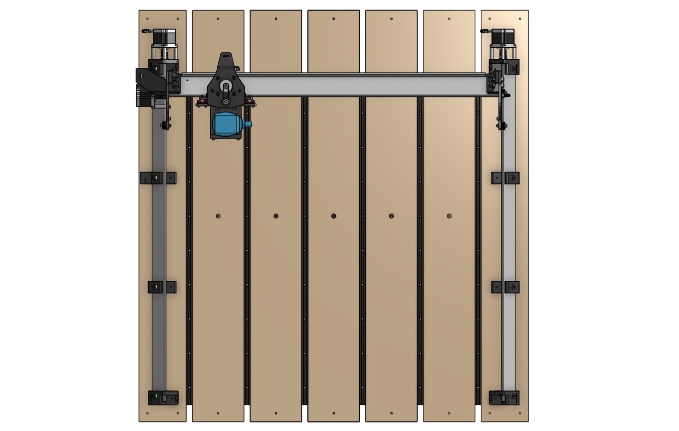
- Cut a 48″ x 48″ x ¾” MDF sheet into five pieces of 6″ wide planks, and two pieces of 5 ½ ” wide planks.
- Lay out the T-tracks and planks on the table, and fasten them down with wood screws. The machine will sit on top of the 5 ½” planks, as the 6″ planks are arranged between them. They should be fastened with screws at least 1″ in length. Leave about 1″ of space between the screws and the ends of the MDF planks.
- To ensure your planks are flat against your table, drill counterbore holes in the middle of the 5 ½” planks. You can use the LongMill, a counterboring bit, or a larger drill bit to create the holes, making sure you have removed enough material to recess the screw heads and surface the MDF planks at least 1mm deep. Then fasten them down with wood screws.
- Complete the rest of the Table Mounting process as described previously if not yet done: https://resources.sienci.com/view/lm-table-mounting/
- Surface the MDF planks, as you would normally conduct wasteboard surfacing: https://resources.sienci.com/view/lm-surfacing-wasteboard/
- Mount your clamps or clamping system onto your newly installed T-track table, and enjoy!
The T-Clamp System
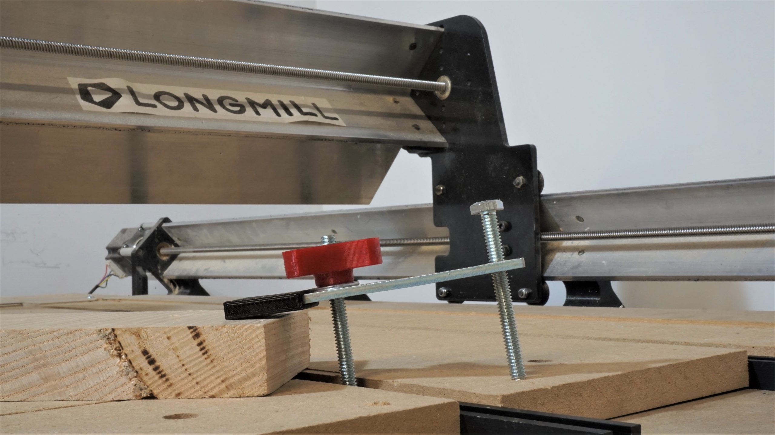
T-clamps are simple and reliable workholding tools that are used alongside T-Track tables. We’ve come up with T-clamps that work for various metals, plastics and woods, and hold down materials from 0.1″ to 1″ thick. These clamps are ideal for holding down small to medium sized pieces of material and also leverage their plastic ends to ensure you’re covered in case you cut a little closer to the clamp than you expected. Inside the package you’ll find:
- Steel clamps (x6)
- Knobs with inserts (x6)
- 3D printed end caps (x6)
- Hex head machine screws (x12)
- Flat washers (x6)
- T-track rails (x6)
- Wood screws (x100)
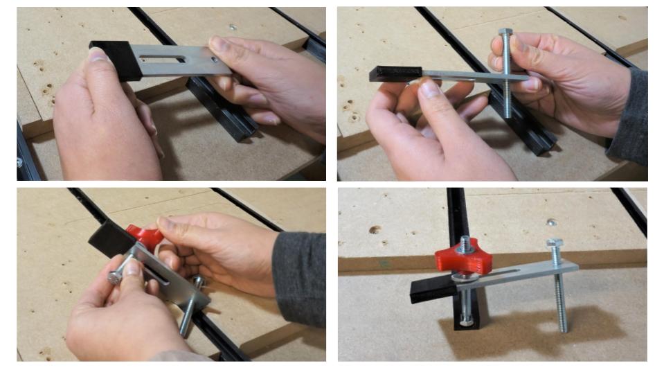
To assemble the T-Clamps:
- Push the plastic end cap onto the steel clamp – the end with two holes. It should have a slight wiggle but should not be easy to remove.
- Fasten a hex bolt onto the other end of the clamp. We recommend the hex head to be facing upwards so that it easily slides into the t-track, but you can change it if desired.
- Slide the other hex bolt through the clamp slot, with the hex head facing down. Bring the washer and knob from the top, so that the washer is contained between the clamp body and knob.
- Now you can slide the downward facing hex bolt onto the t-track and locate the clamp for mounting material.
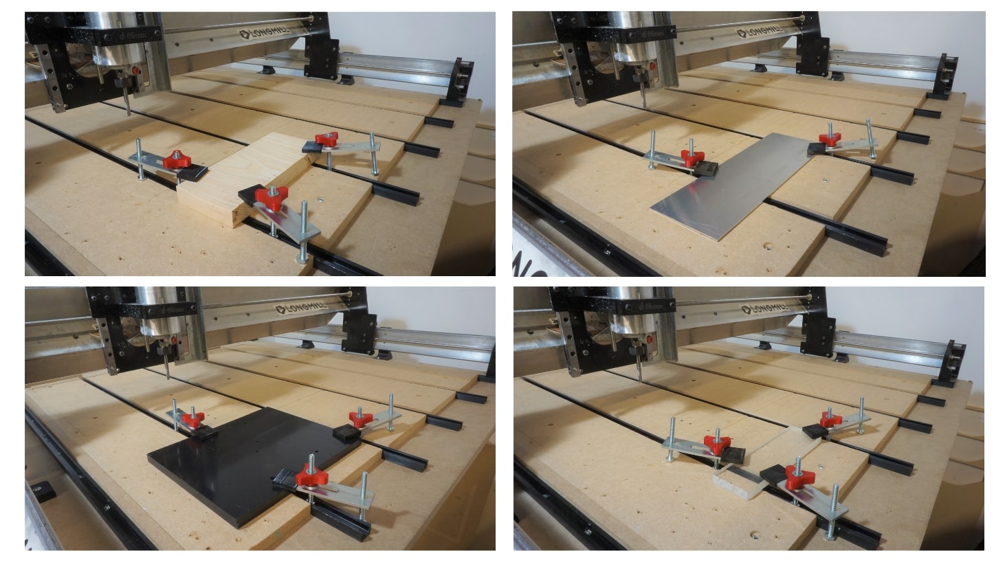
To use the T-Clamps:
- Slide the hex bolt head through the t-track so that the entire clamp is on the table. You may need to adjust the bolt and knob to have it fit onto the table.
- Place your workpiece onto the table.
- Move and adjust the clamp to push down onto the workpiece, ensuring that the end cap side of the clamp is lower than the bolt end. Tighten both bolts until snug. Position the clamps so that there is enough space for your cutting job on your workpiece.
- Push your material to check if it is secured onto the table. If not, use more t-clamps or other workholding methods.
Making your own clamps
The great thing about having a CNC machine is that you can make your own clamps for it!
For full details and file downloads, please see the full article.
Spring-loaded Nuts
The T8 Spring Loaded Anti-Backlash Nuts are compatible with LongMill MK1 & MK2 designs, and ship by default with the MK2.5. The only exception is if you have a LongMill 48×30 in which case the X-axis requires the larger T12 Spring Loaded Nut.
Anti-backlash nuts are used on the LongMill to both reduce backlash on the lead screws and to compensate for wear over time. These spring-loaded nuts are a novel design by Sienci Labs which bring traditional anti-backlash nuts to the next level by introducing auto-tensioning. This means you won’t need the manually tension these nuts or adjust them over time, as they will take care of this on their own. You can read more about this in our blog post about them.
Upgrading to the new nuts is fairly simple, the only parts you need are the new nuts and the Allen key provided for assembly, all other hardware is reused. The fastest way to follow these steps will be to have easy access to all sides of your machine and have your machine turned on so you can jog it around. Once you swap out the first nut, you’ll find that swapping out the other 3 is very similar! Follow the instructions below or watch the video if it helps.
Y-Axes
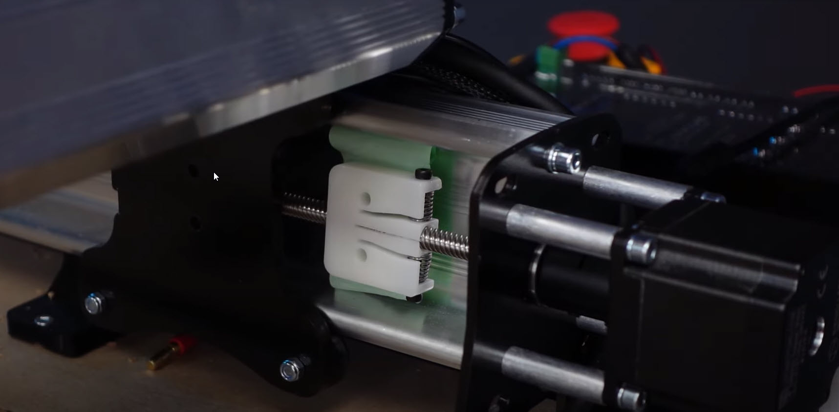
We are replacing 4 nuts, one on each Y-axis plate (left and right) and two next to each other at the XZ-gantry.
- Jog the Y-axis close to the back of the machine.
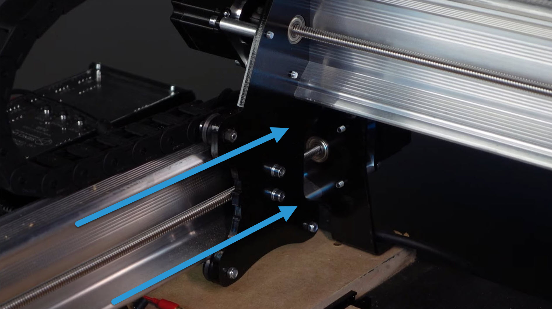
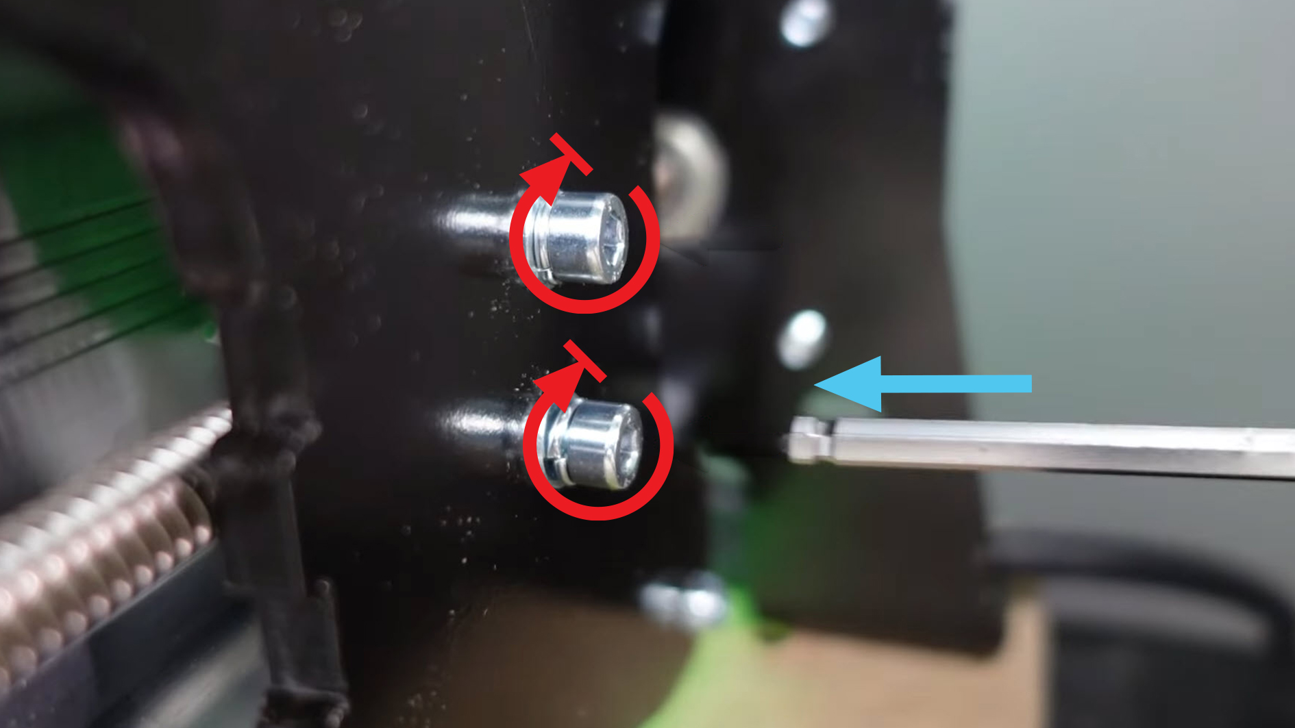
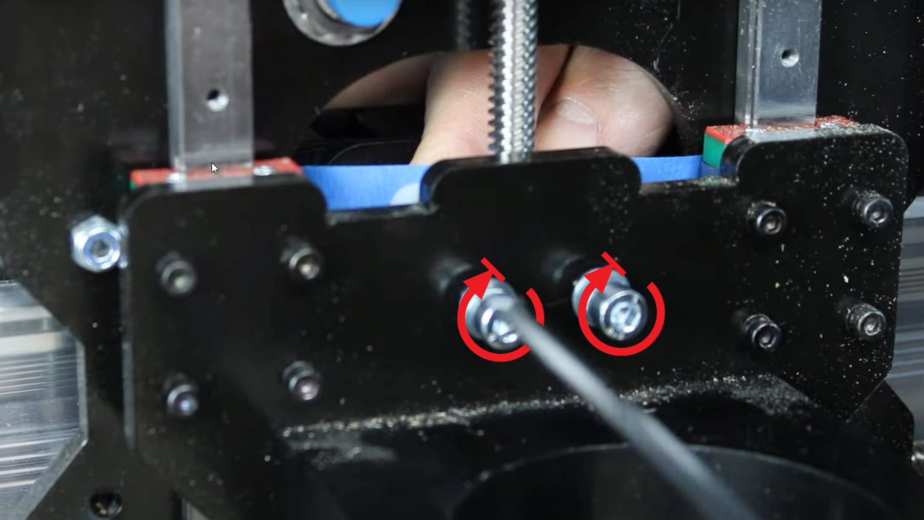
- With your Allen key, remove the two M5 mounting screws from the backlash nuts on the Y-axis plates on both the left and right sides. Once they’re removed, manually push the Y-axis away from the nuts so you can reach them underneath.
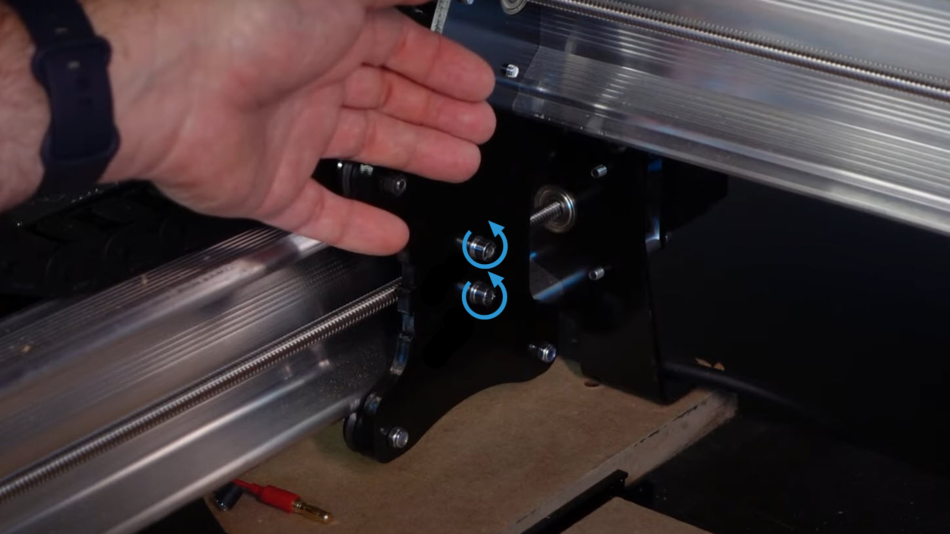
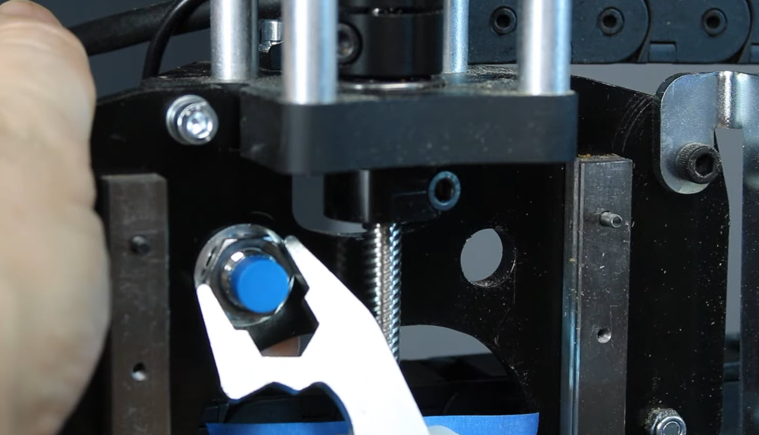
- On the motor coupler, loosen the screw on the lead screw side. Do this until you can slide the lead screw out through the bearing completely.
- Rotate the lead screw until the old backlash nut is off, or rotate the nut itself.
- Grab a new T8 spring loaded nut and thread it onto the lead screw, with the spring side facing the motor/back.
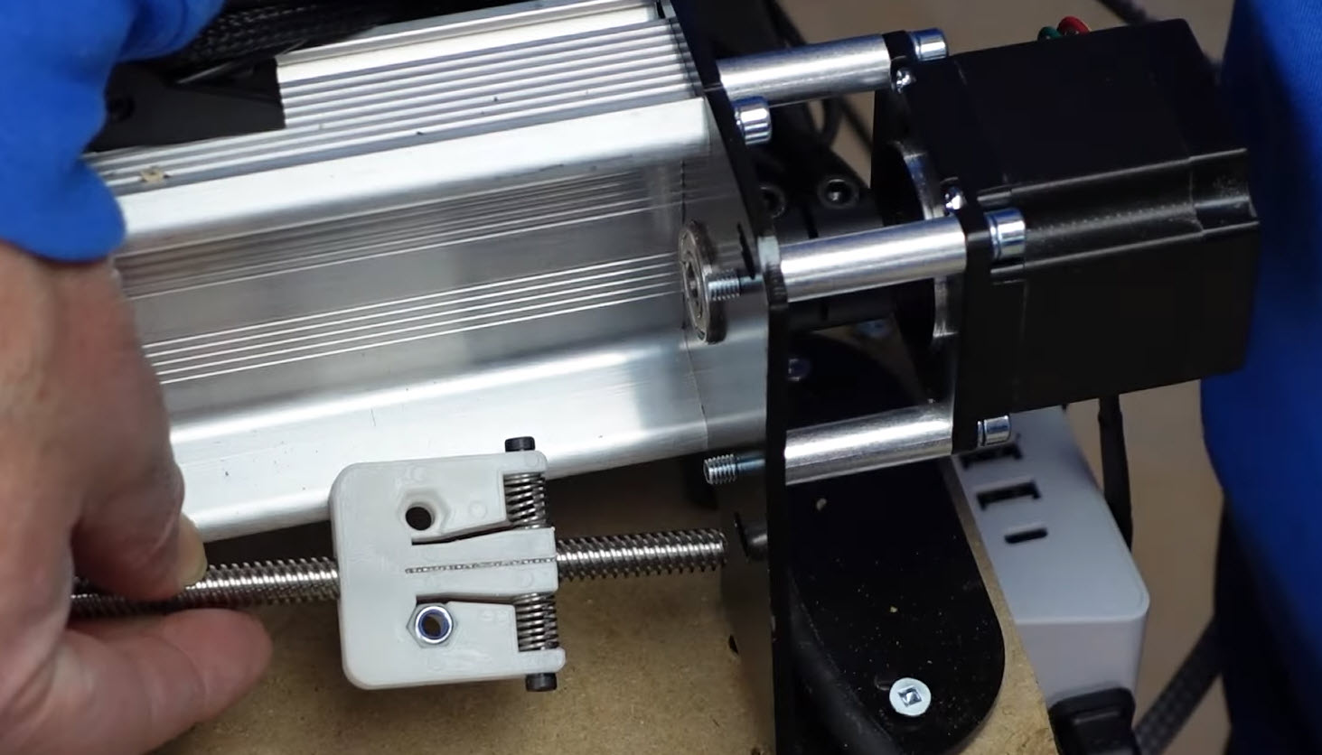
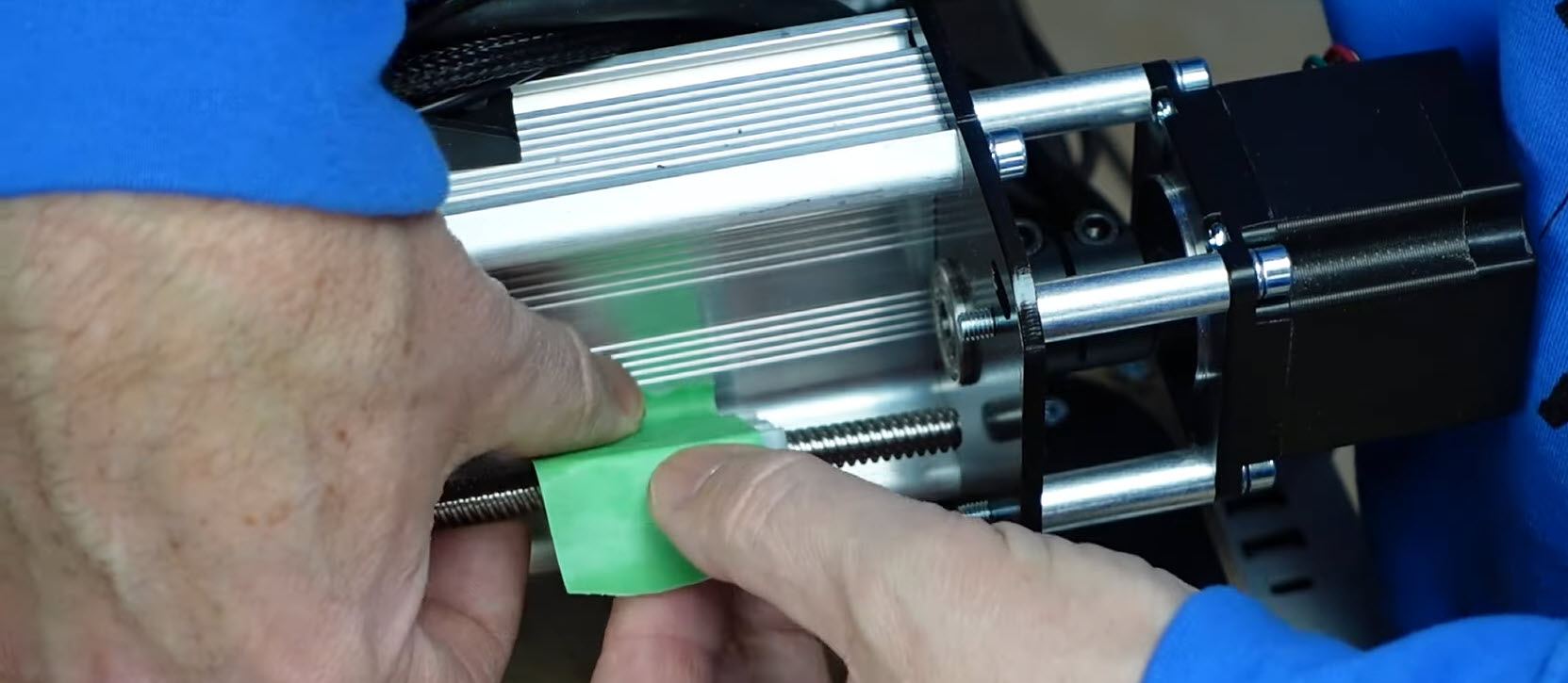
- Push two nylon lock nuts into the back of the spring loaded nut (rounded side of the nylon nuts should face out) and apply a piece of tape to hold them in place during installation.
- Put the lead screw back into the motor coupler and tighten the screw back down. Remember to repeat steps 3 – 7 for the right Y-axis if you haven’t been mirroring the steps as you went along.
- Great job! Now push the Y-axis to the back again, over the new backlash nuts and reinstall the mounting screws. Tighten until the split washer is compressed, alternating between both bolts to maintain even pressure, being careful not to over tighten them. Repeat this step for the right side of the Y-axis.
You can now remove the tape, you’re already over halfway through this upgrade!
X-Axis
Just like with the Y-axis, we want to be close to the motor to remove the lead screw, so jog your X-axis all the way to the left side to begin the same process we just completed on the Y-axis.
Note that if you have a 48×30, you will need to use a T12 nut instead of a T8 nut since the lead screw is larger.
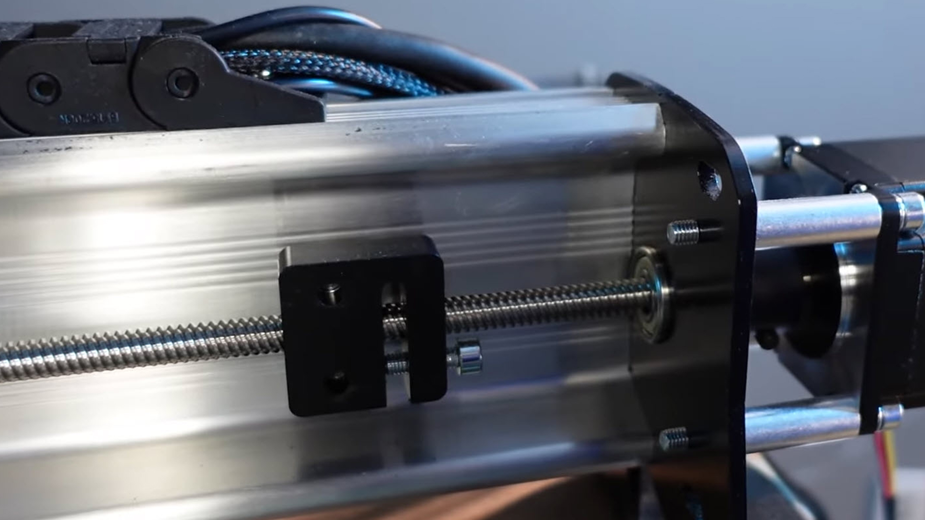
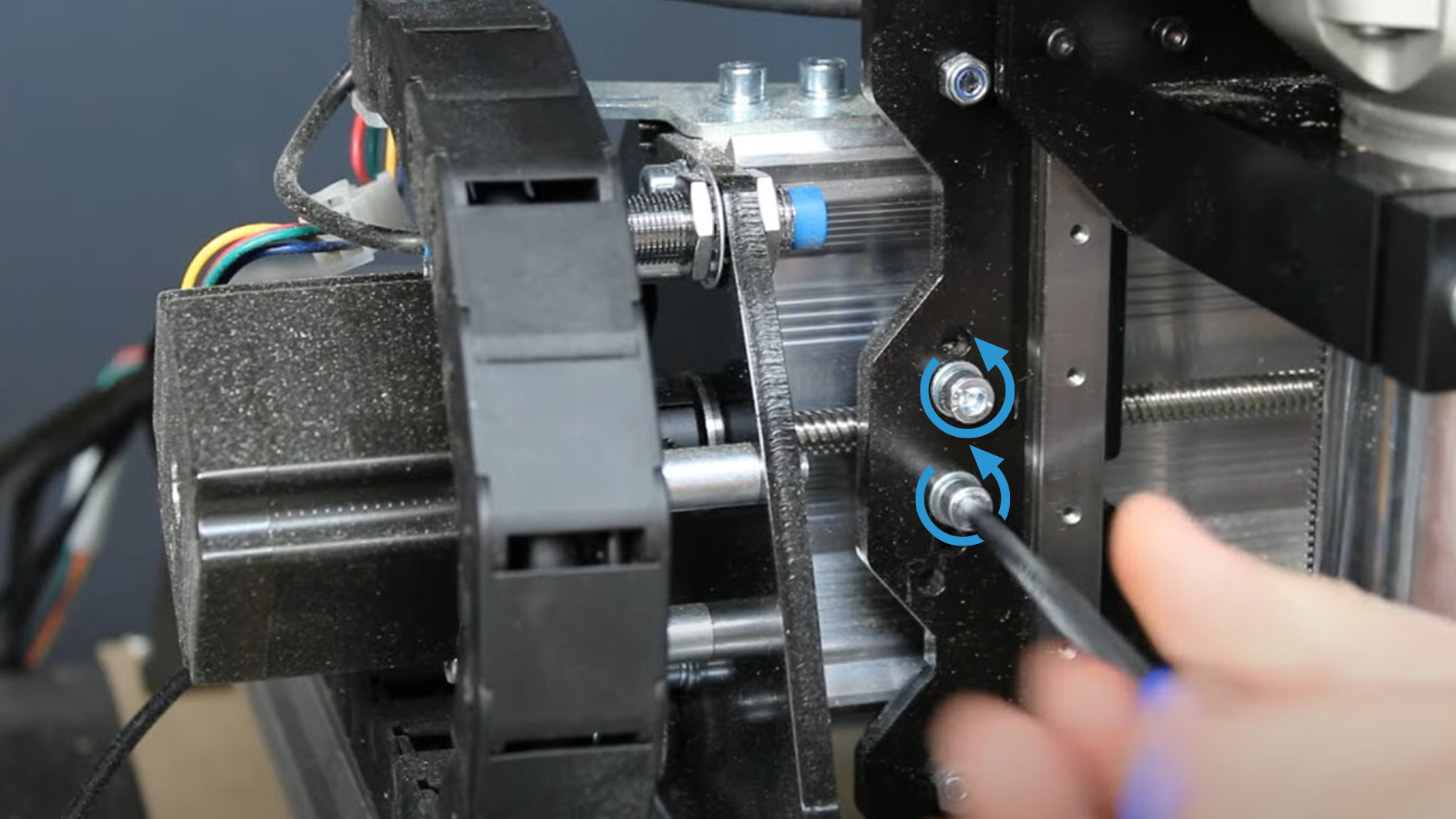
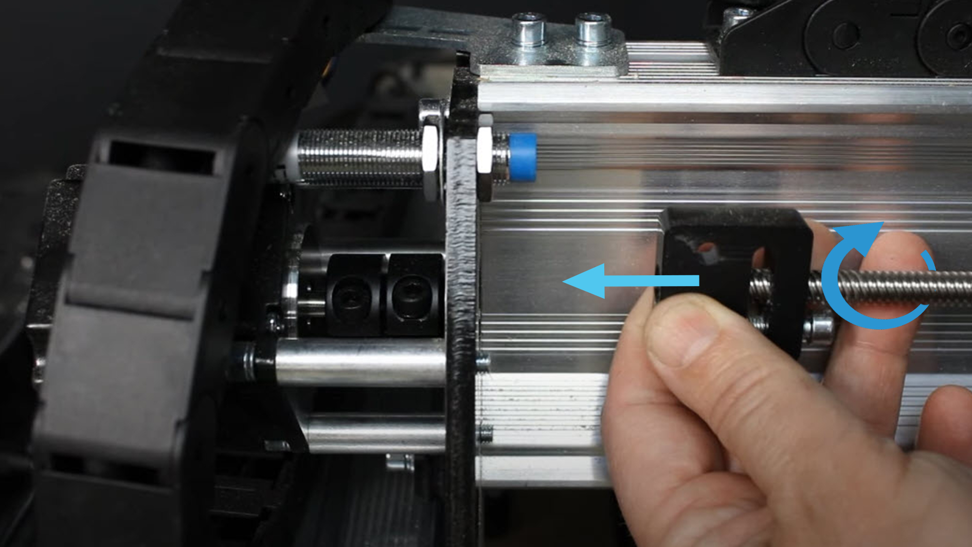
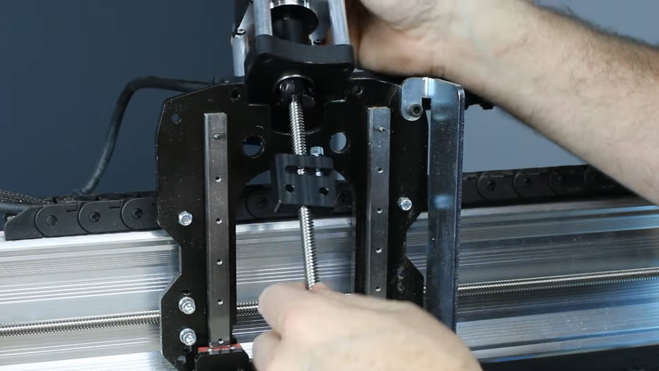
- With the X-axis moved to the left side, remove the mounting screws from the backlash nut, then manually push the X-axis to the right to expose the old backlash nut.
- Loosen the screw on the lead screw side of the motor coupler and slide the lead screw out through the bearing.
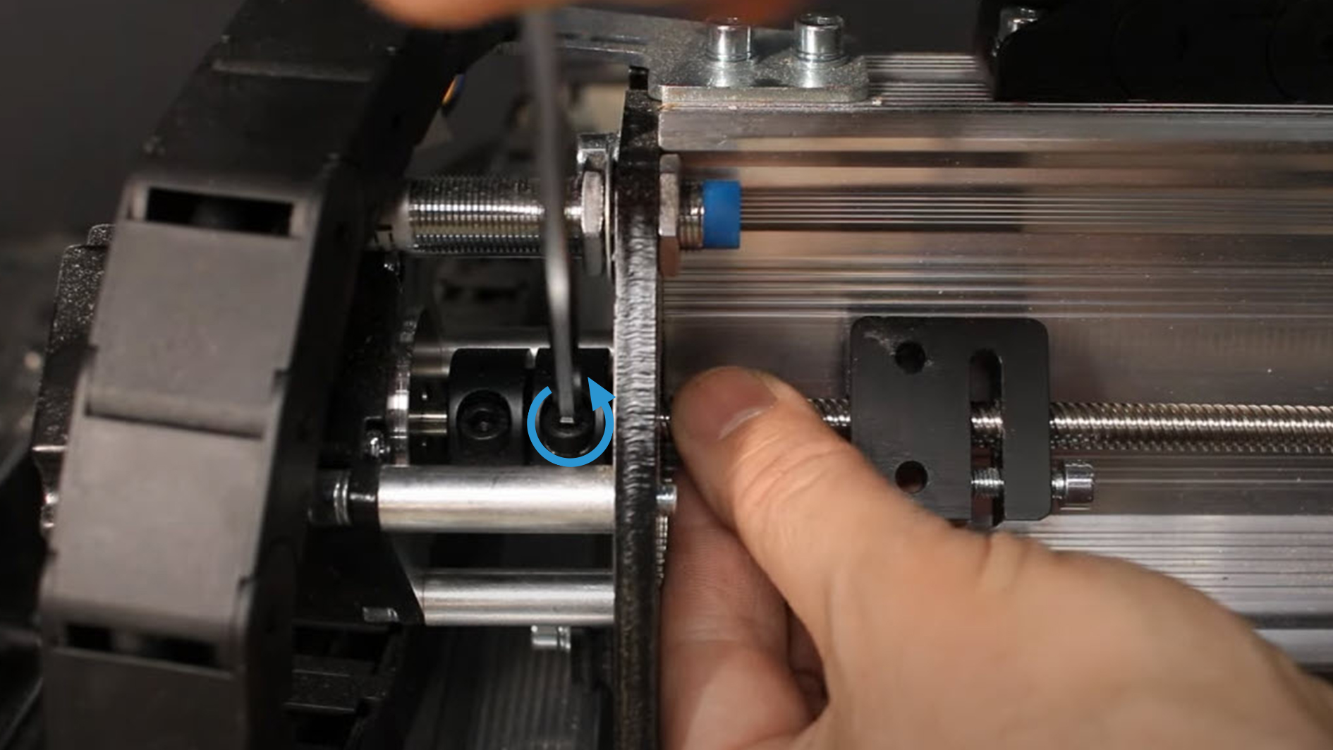
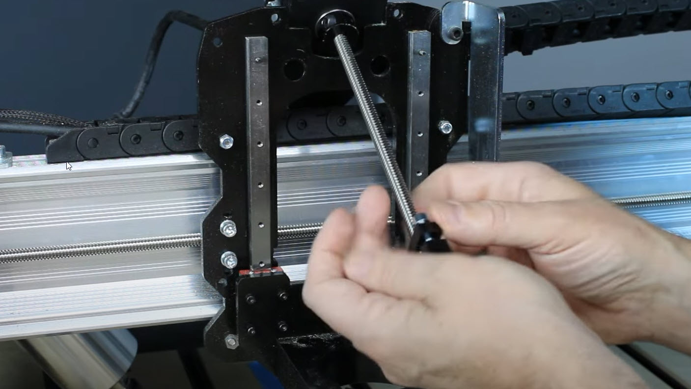
- Rotate the lead screw until the old backlash nut is off, or twist the nut itself to remove it.
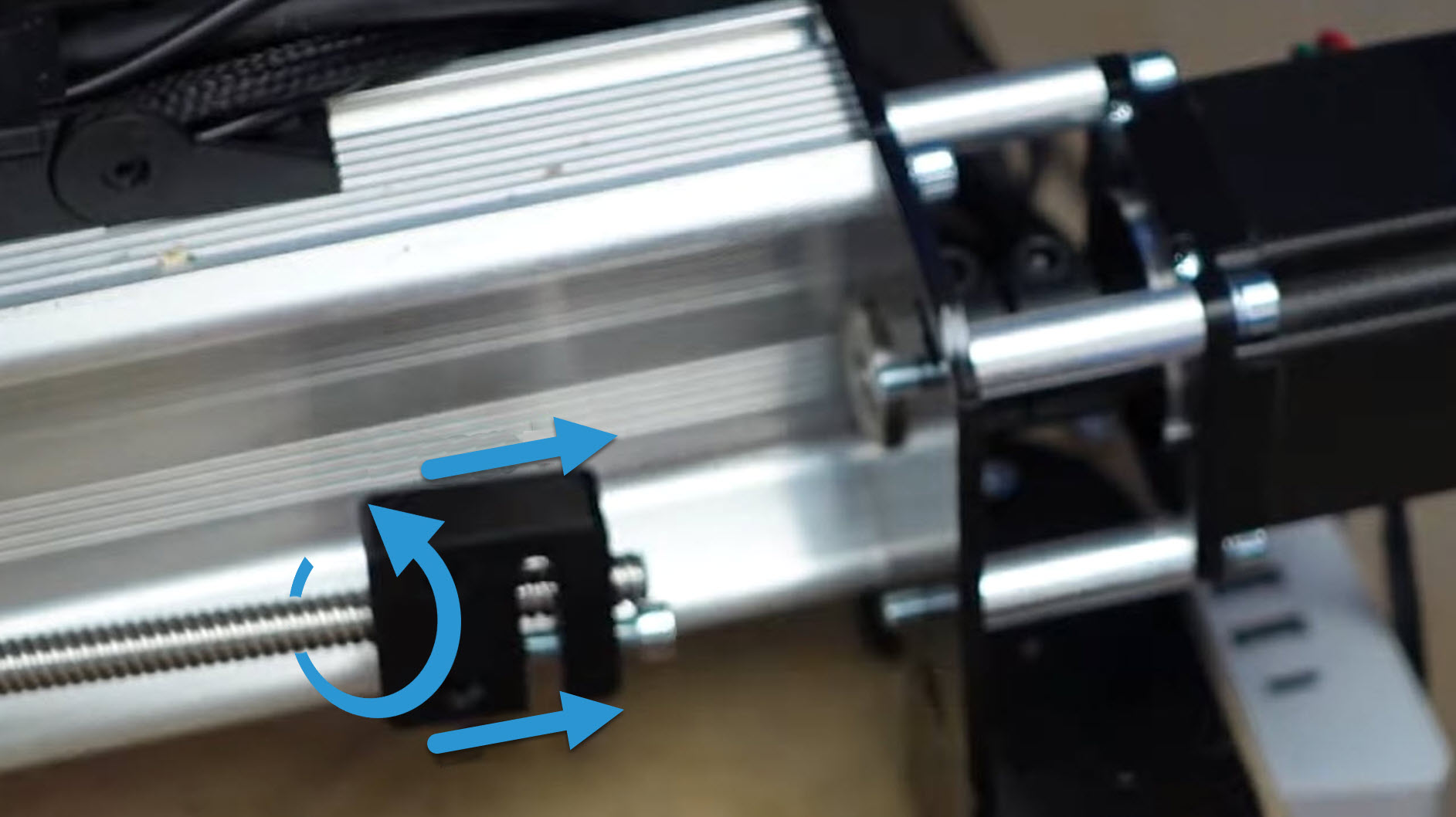
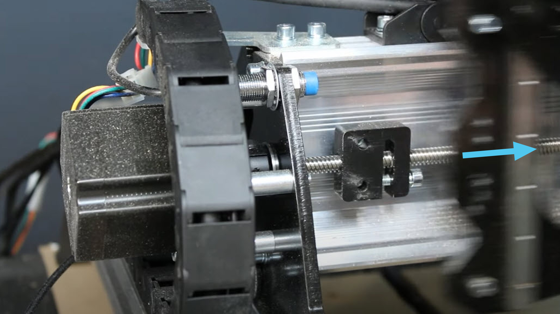
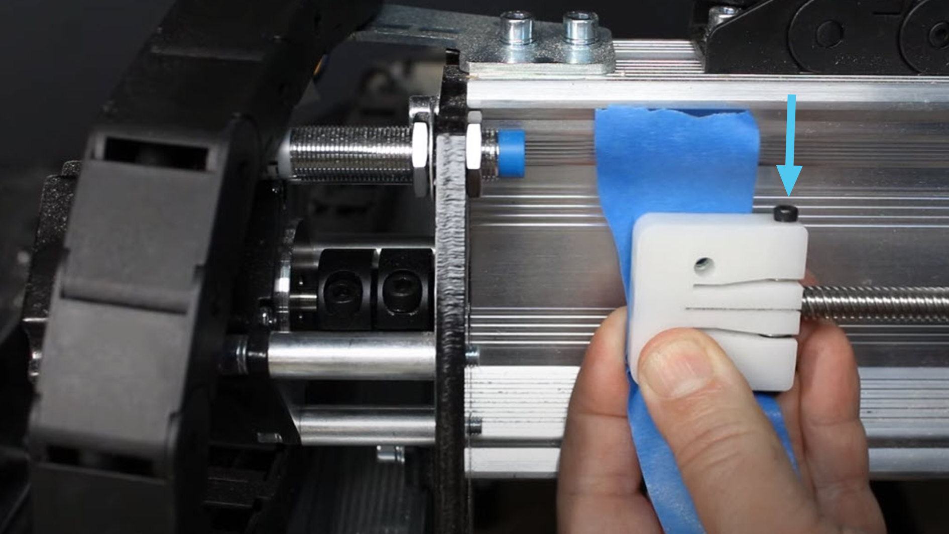
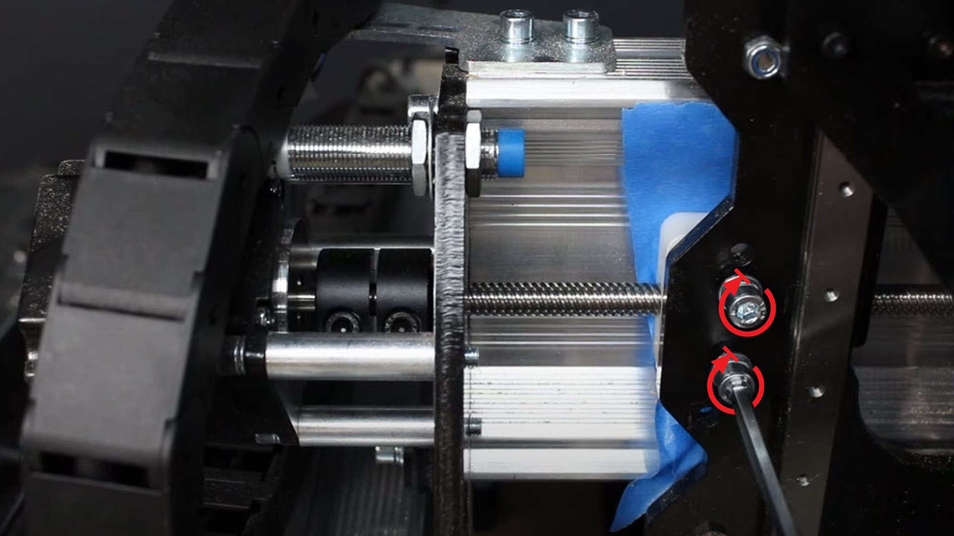
- Thread the new spring loaded nut onto the lead screw, with the spring side facing to the right (double-check the picture). Similar to before, push two nylon lock nuts into the back of the spring loaded nut (rounded side of the nylon nuts should face out) and apply a piece of tape to hold them in place during installation.
- Put the lead screw back into the motor coupler and tighten the screw back down.
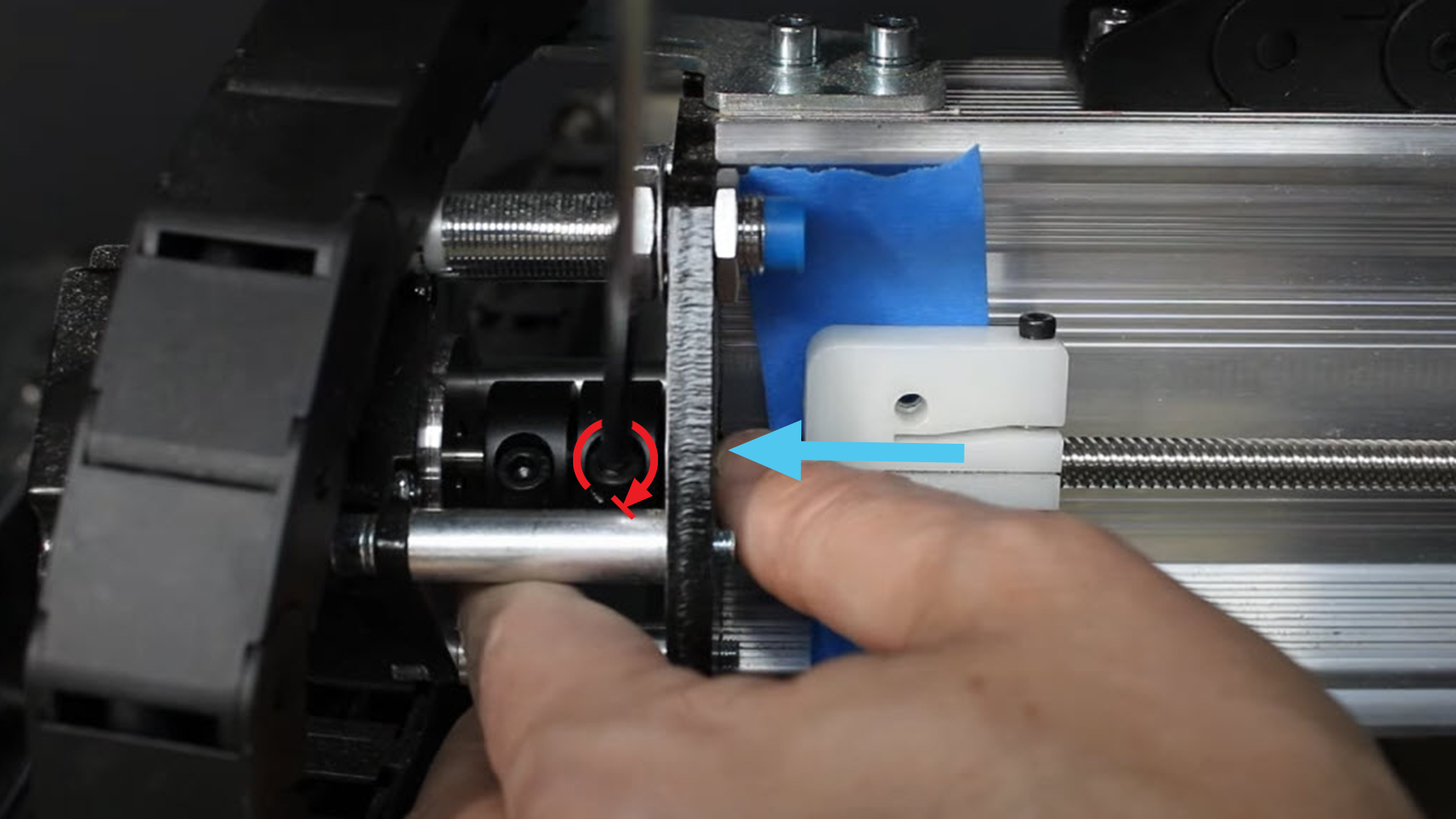
- Push the X-axis back over the backlash nut and reinstall the mounting screws. Tighten till the split washer is compressed, alternating between both bolts to maintain even pressure, being careful not to over tighten them.
Z-Axis
The Z-axis nut is easier to remove because we don’t have to remove the lead screw from the motor on the MK2 (you will have to do this with the MK1 however).
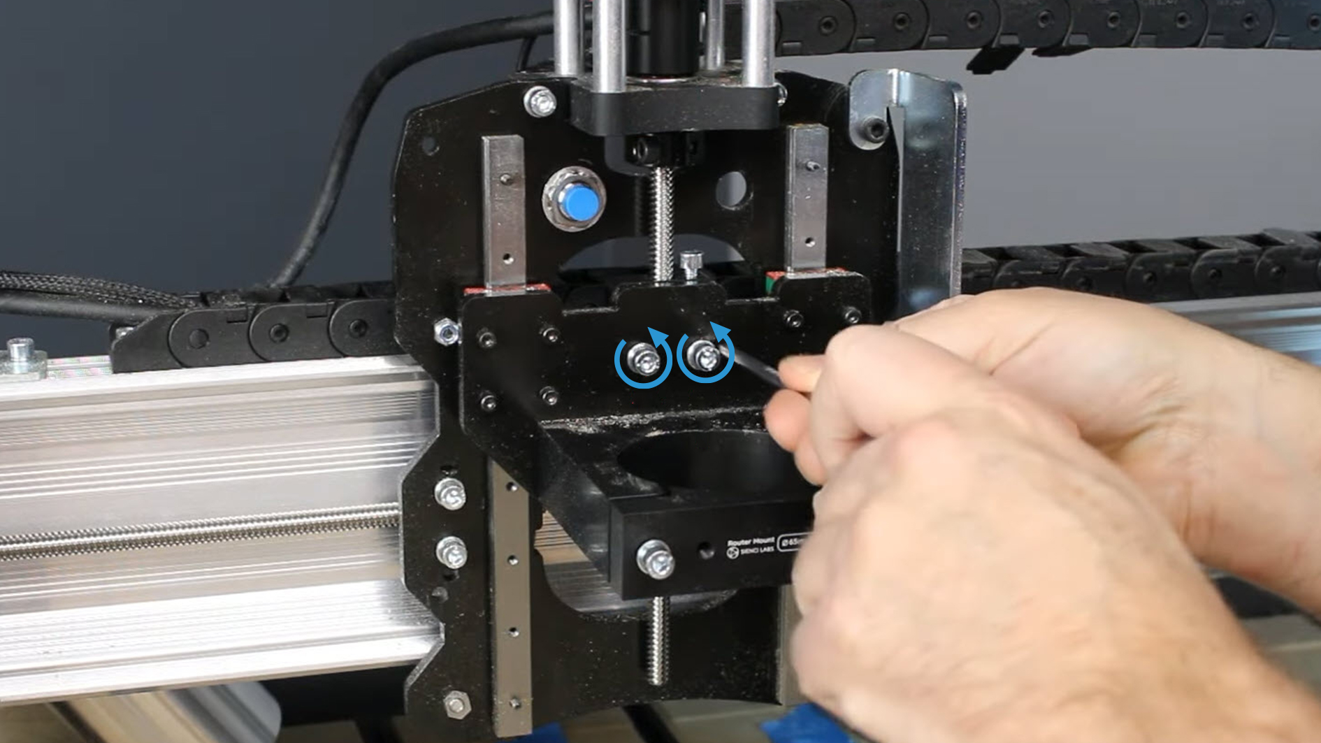
- Jog the Z-axis to be about halfway up the lead screw then remove the two bolts holding the anti-backlash nut.
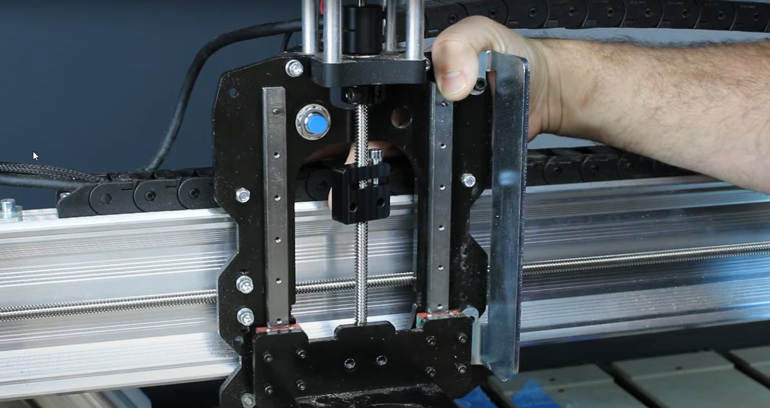
- Once the bolts are removed, the Z-axis plate can be lowered out of the way.
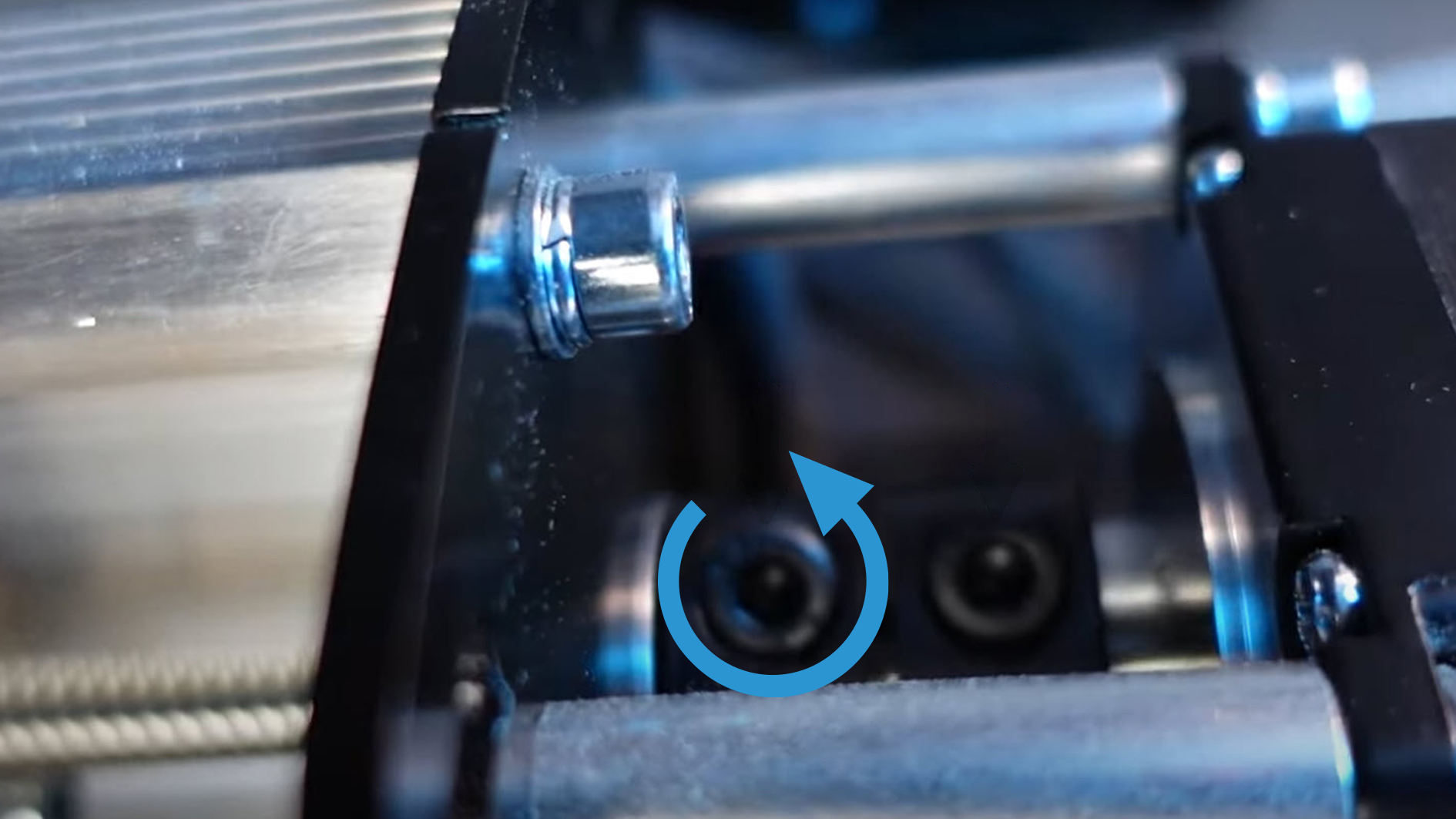
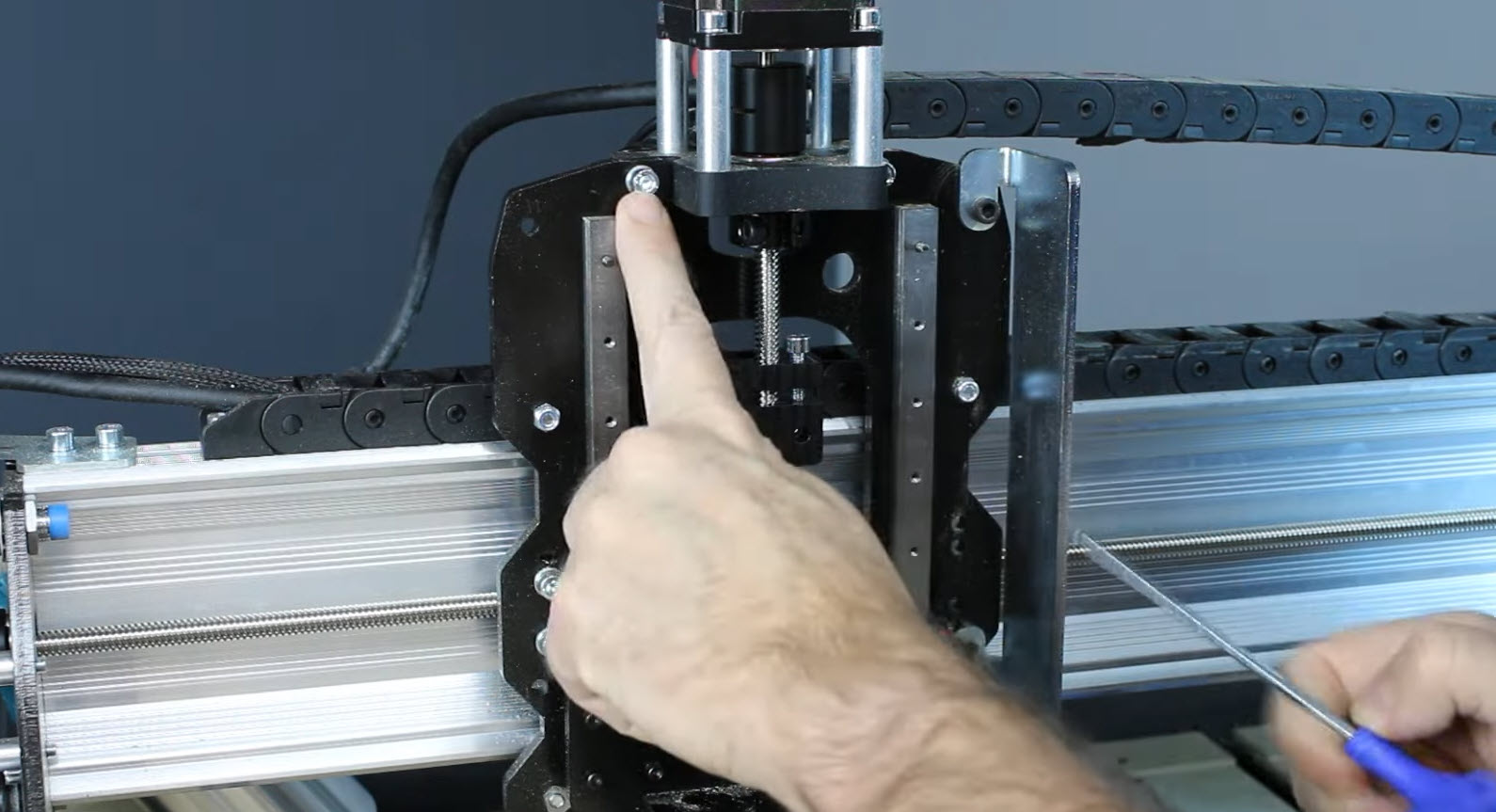
- Remove the two screws that hold the Z-axis mount onto the X-axis plate. If you have limit switches installed, remove the Z-axis one now too.
- Once those two bolts are removed, this will allow you to tip the motor and lead screw backwards.
- Twist the old anti-backlash nut off the bottom of the lead screw.
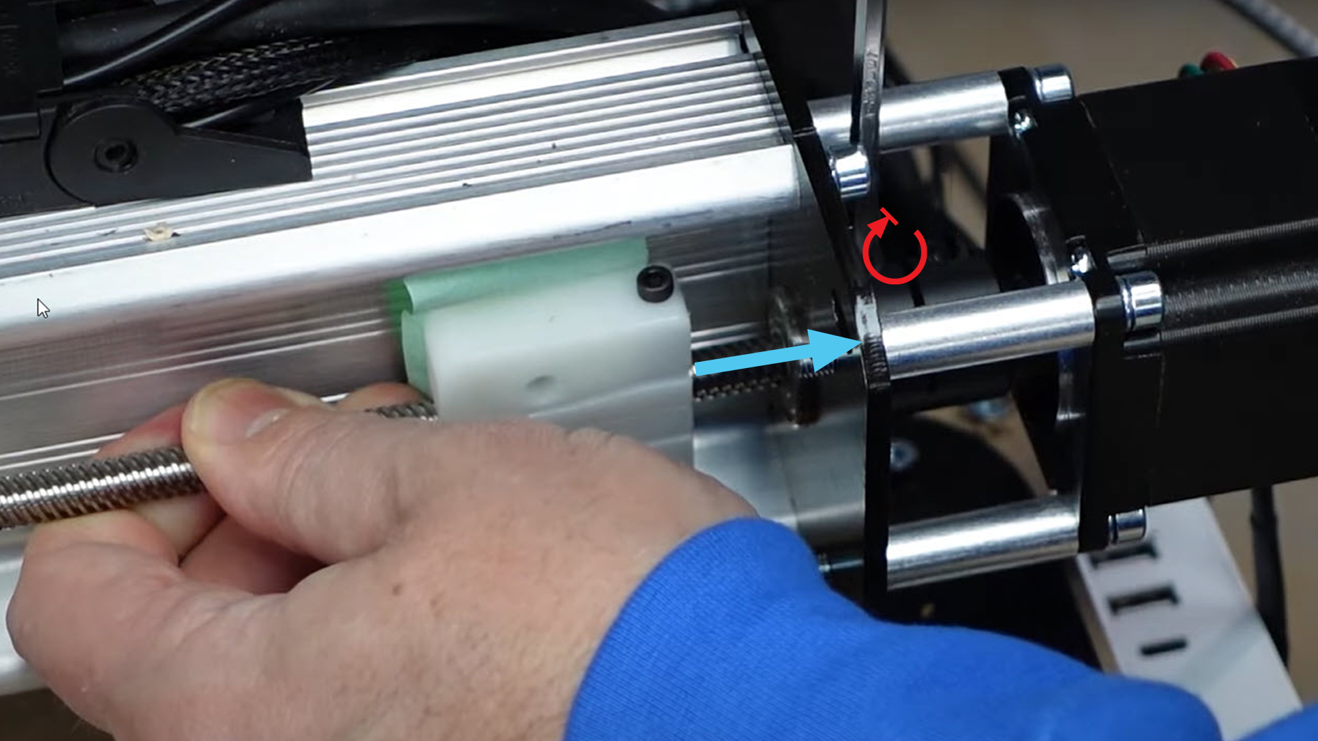
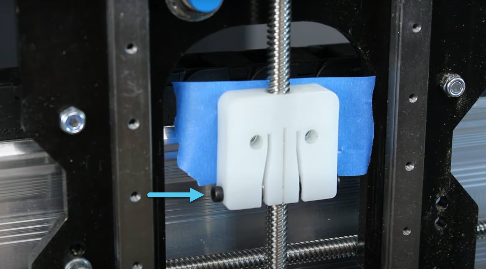
- Thread the new spring loaded nut onto the lead screw, with the spring side facing down, as indicated with the blue arrow. Spin it to the centre of the lead screw, then push two nylon lock nuts into the back of the spring loaded nut (rounded side of the nylon nuts should face out) and apply a piece of tape to hold them in place.
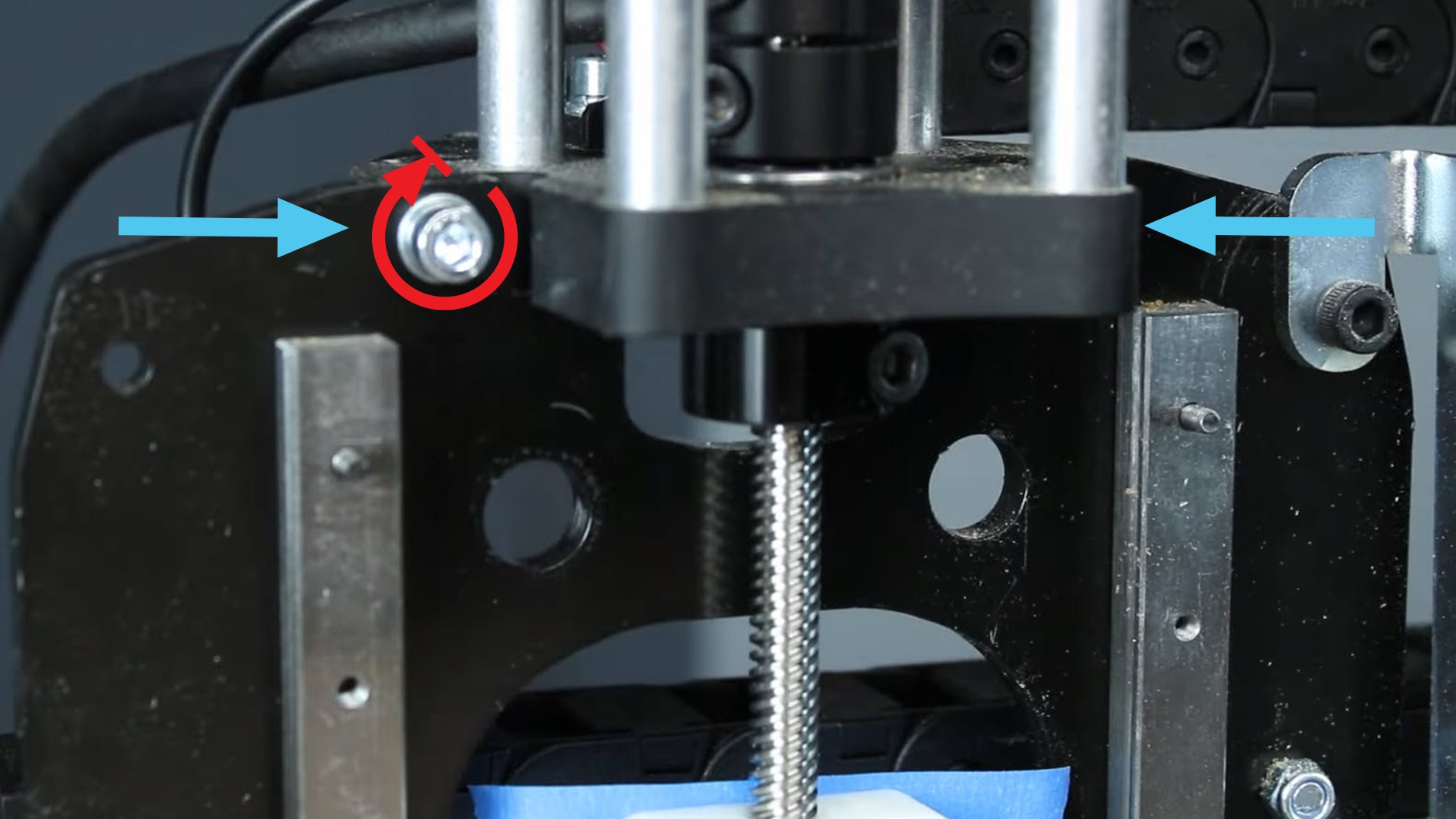
- Reinsert the two bolts to hold the Z-axis mount onto the X-axis plate and tighten them fully.
- Reinstall the limit switch, ensuring that the washer is flat on the top/bottom to give maximum space for your Z axis to travel.
- Push the Z-axis plate back up to align it with the new spring loaded nut and reinstall the 2 mounting screws. Don’t over-tighten. Like before, the 2 screws should be tightened till the split washers are compressed, and you should alternate when tightening them to create even pressure.
Conclusion
Congrats! All of your hard work is complete. You now have an upgraded machine where you won’t have to manually adjust the nuts like with the old version. Still, keep an eye out, since any nuts that run on a lead screw will eventually wear out and need to be replaced.
Troubleshoot
If you finish installing the spring loaded nuts and find that your machine is now getting stuck whenever you try to move fast, we recommend lubricating the lead screw with a light coating of WD-40 or a similar lubricant. Follow this up with a “break-in cycle” where you jog the stuck axis back and forth at a normal speed, increasing to rapid after a few passes. If the nut binds on rapid, reduce the speed to normal and re-run a few more passes.
Once it seems sorted out, wipe the lubricant back off the lead screw to prevent increased buildup of dust. If you have any other issues with the spring loaded anti-backlash nuts, make sure to carefully re-read the assembly instructions or reach out to us for help.
Community posts
If you want to learn why this part has been upgraded, you can check out the video below where Andy chats about the evolution of the spring loaded nuts. You can also check out a couple of our community links for a couple solutions our users have found.
| Topic | Type | Link |
|---|---|---|
| Spring Loaded Anti-Backlash Nut Update Video | 17 min Video | Watch |
| Coupler Found to be Slipping After Upgrade | Community Post | Read |
| Replacement Parts Sent Out | Community Post | Read |
Regular Dust Shoe