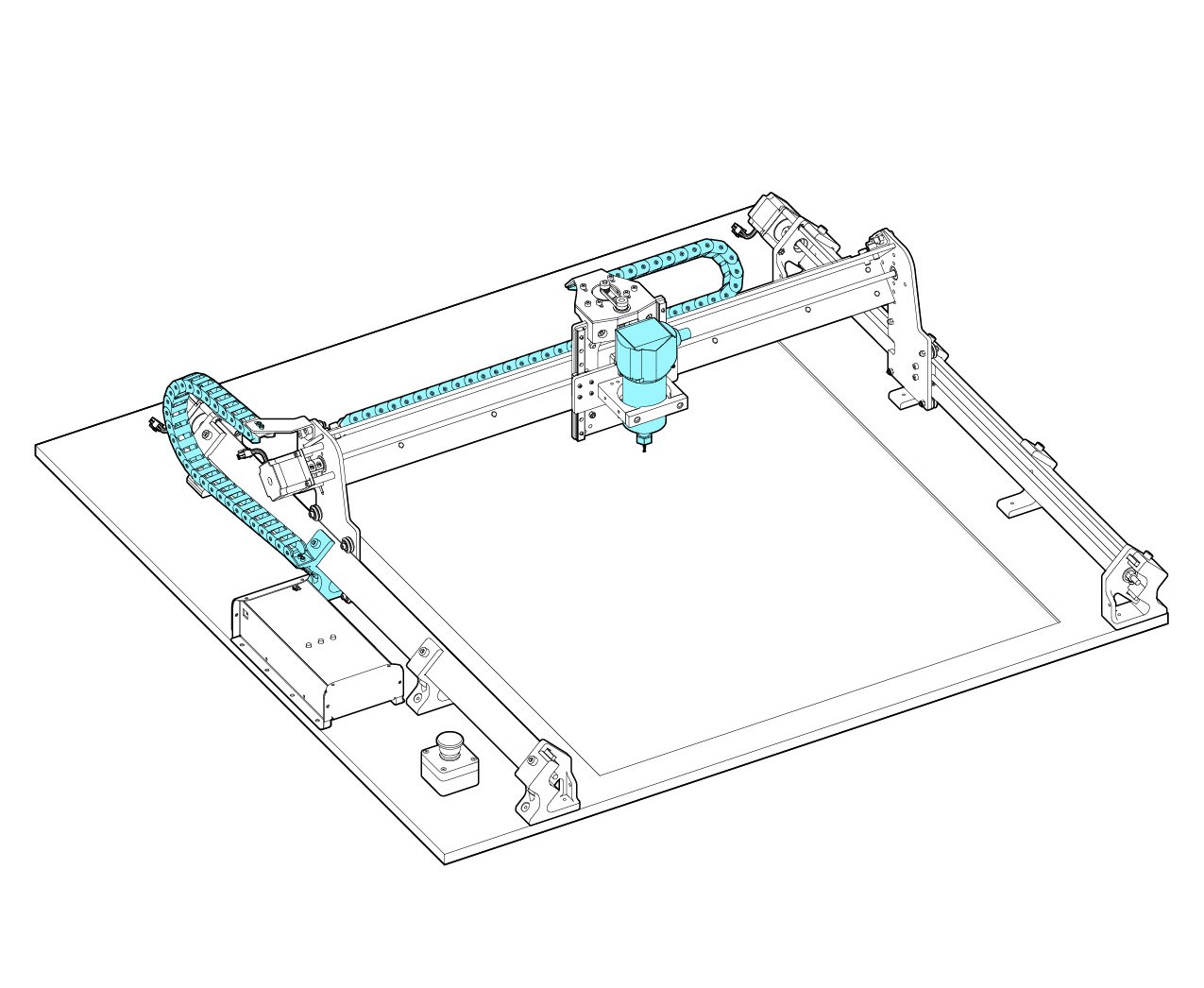
Drag chains and Wiring
We will now be installing the drag chains; these contain and guide the wires on the LongMill so they aren’t in the way during cutting. They also keep wires from wearing out from bending or being cinched around corners.
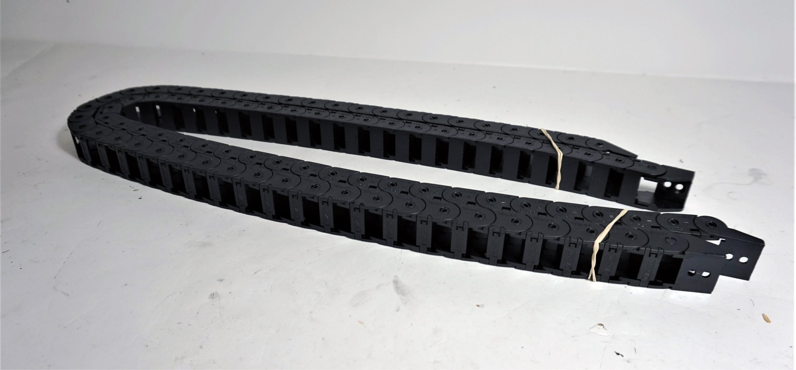
As mentioned previously, the chains can be found in the lighter long box (pictured). They come with detachable links so that you can adjust their length depending on the size of your LongMill. You can save these links for later when you upgrade to a larger LongMill if you have the 12×12 or 12×30 versions.
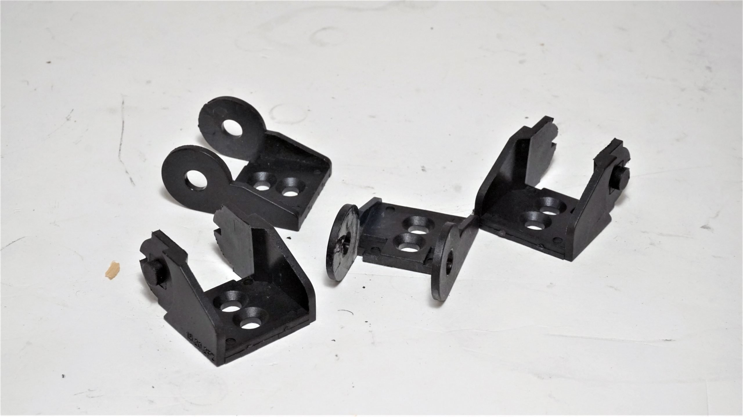
We’ll first start by removing the end connector links from both drag chains. You can either pull or squeeze off the connector as shown in the photos. A flat head screwdriver or thin shim can also be handy for this, just be careful not to cut yourself in the process.


Do this for all four end pieces, two hole-types and two pin types, and set them aside.
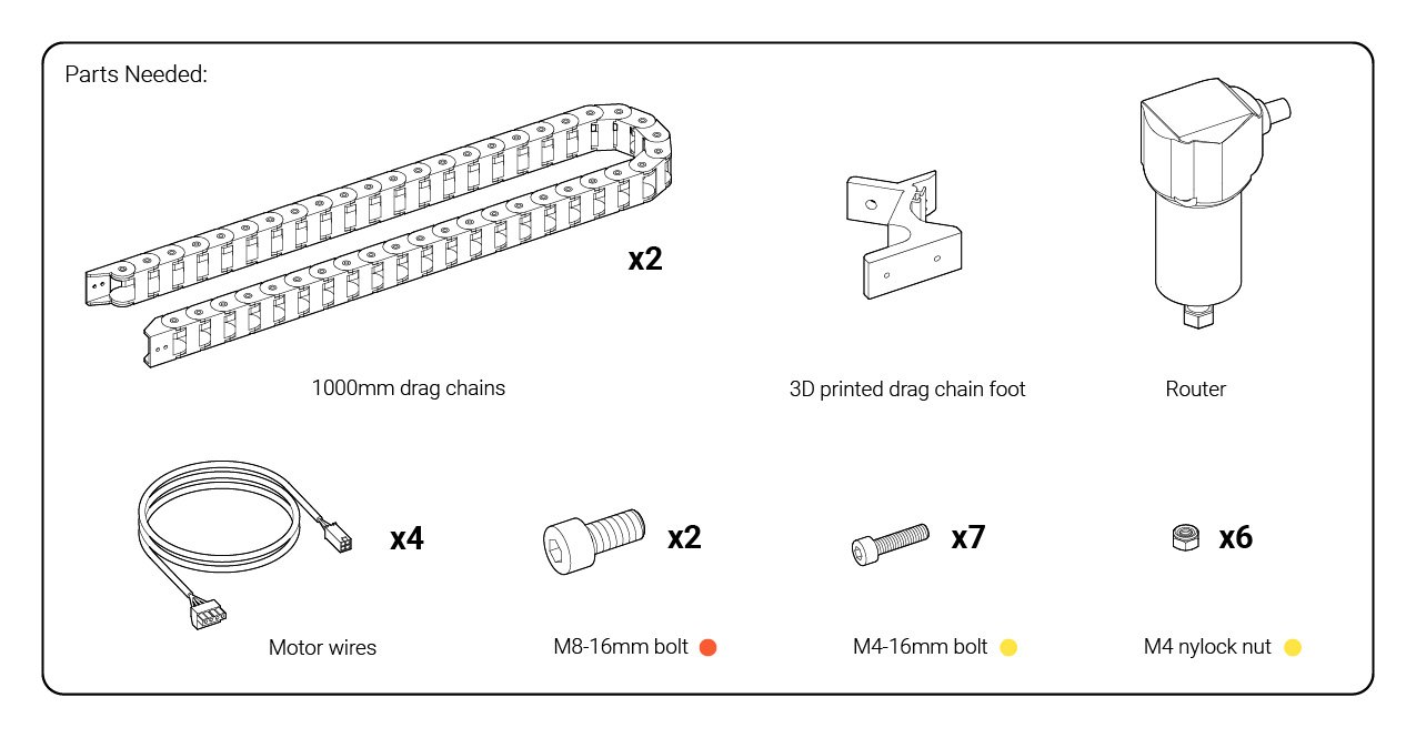
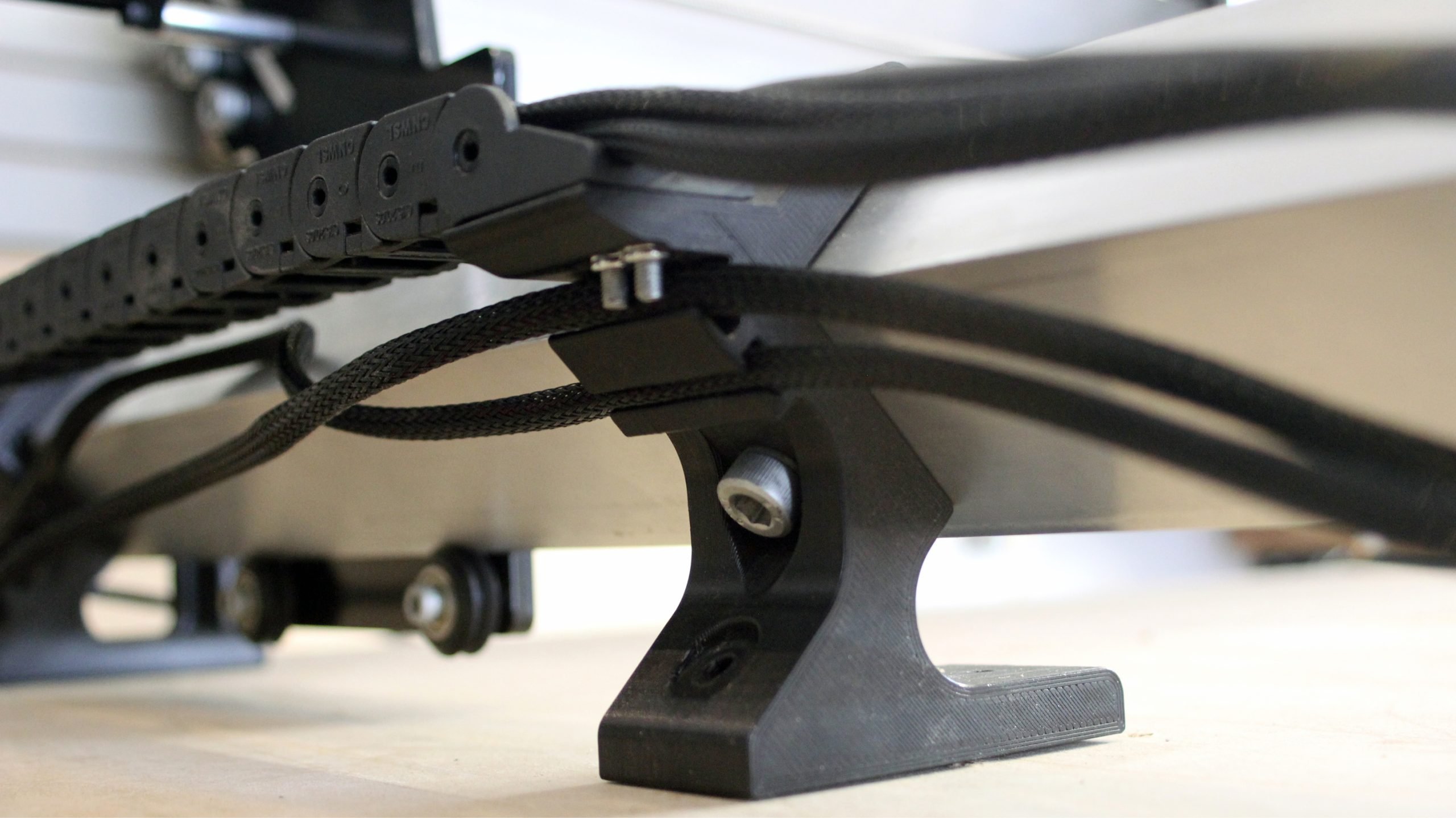
We will attach these links to the machine, starting with the drag chain foot you set aside in the last step. It can be identified by its lightning bolt shape and the nut catches and wire clips it has on its back side. Also find the smaller M4 bolts and nuts in the yellow bag, as these will be used to attach the links in the following steps.
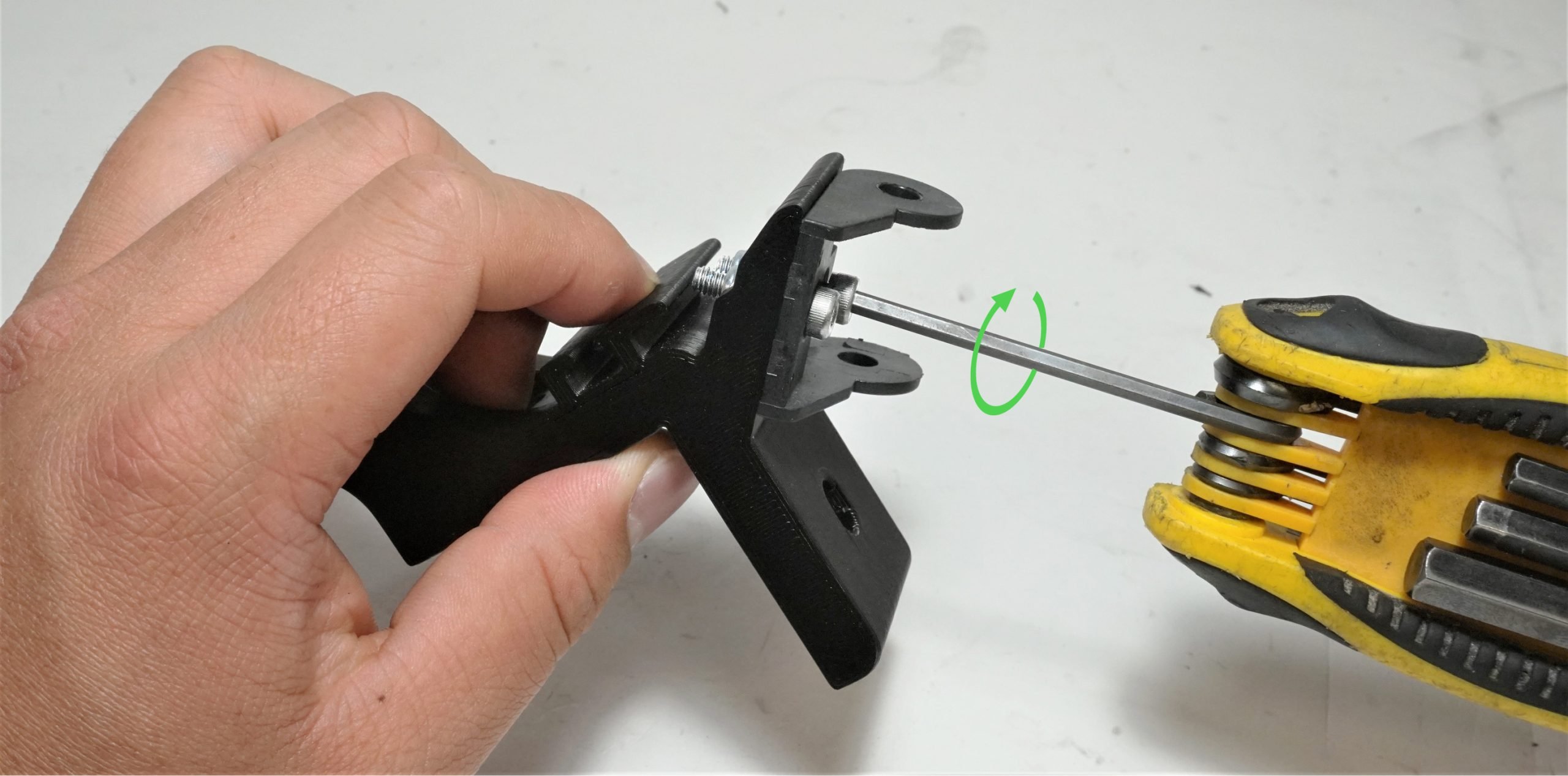
Use a pair of bolts and nuts to secure the hole-type end link onto the drag chain foot in the orientation shown by using a size 3 Allen key. The nuts should fit into the hexagonal cutouts underneath the mounting point, meaning a wrench won’t be needed.
This last foot can now be attached to the Y-axis rails in the vacant space on the left side of the machine. Use two of the short M8 bolts to fasten it to the rail, similar to how all the other feet have been mounted.

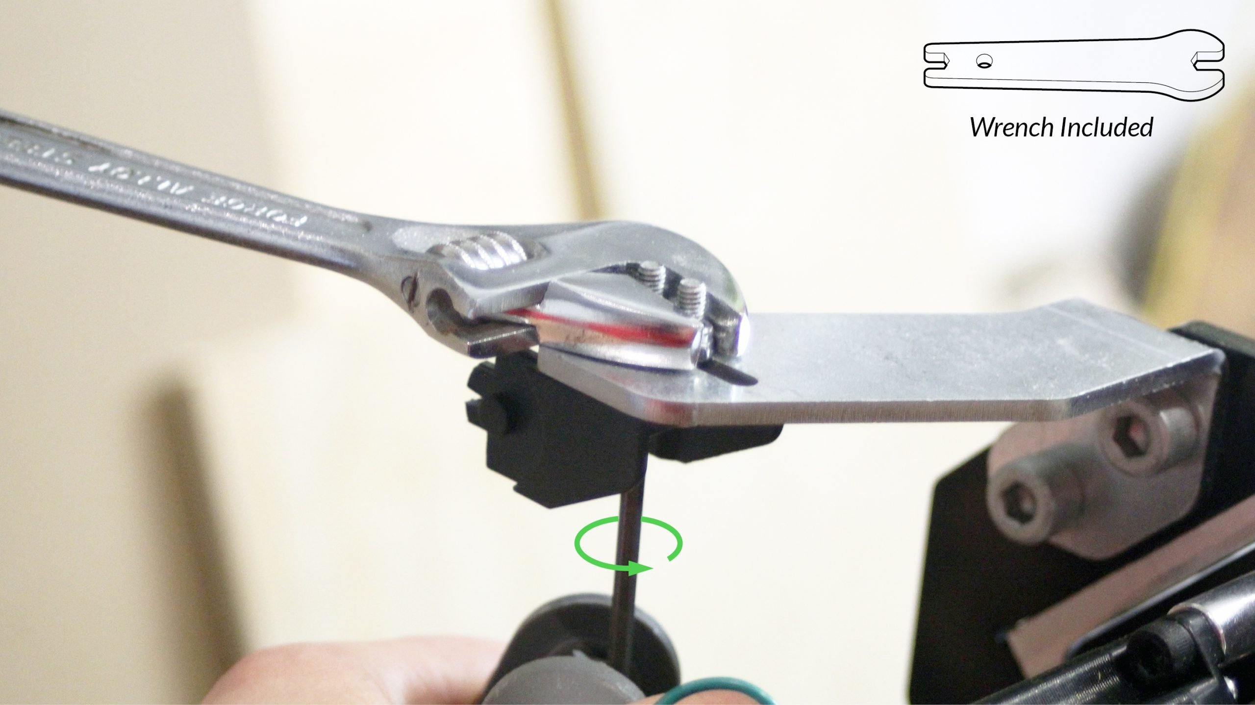
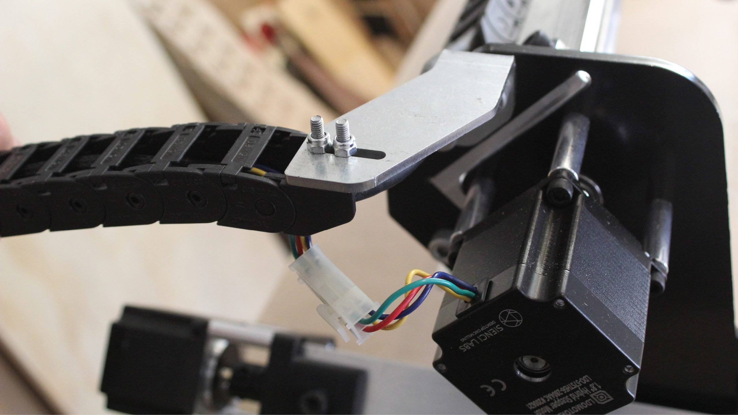
Now get a pin-type end link (pictured) to mount the other end of the drag chain. This one will attach the the X-axis clip-on mount where there’s a slot for the two bolts to fit through. Use the included LongMill wrench to hold the nuts from the top while you fasten the bolts from underneath with a size 3 Allen key.
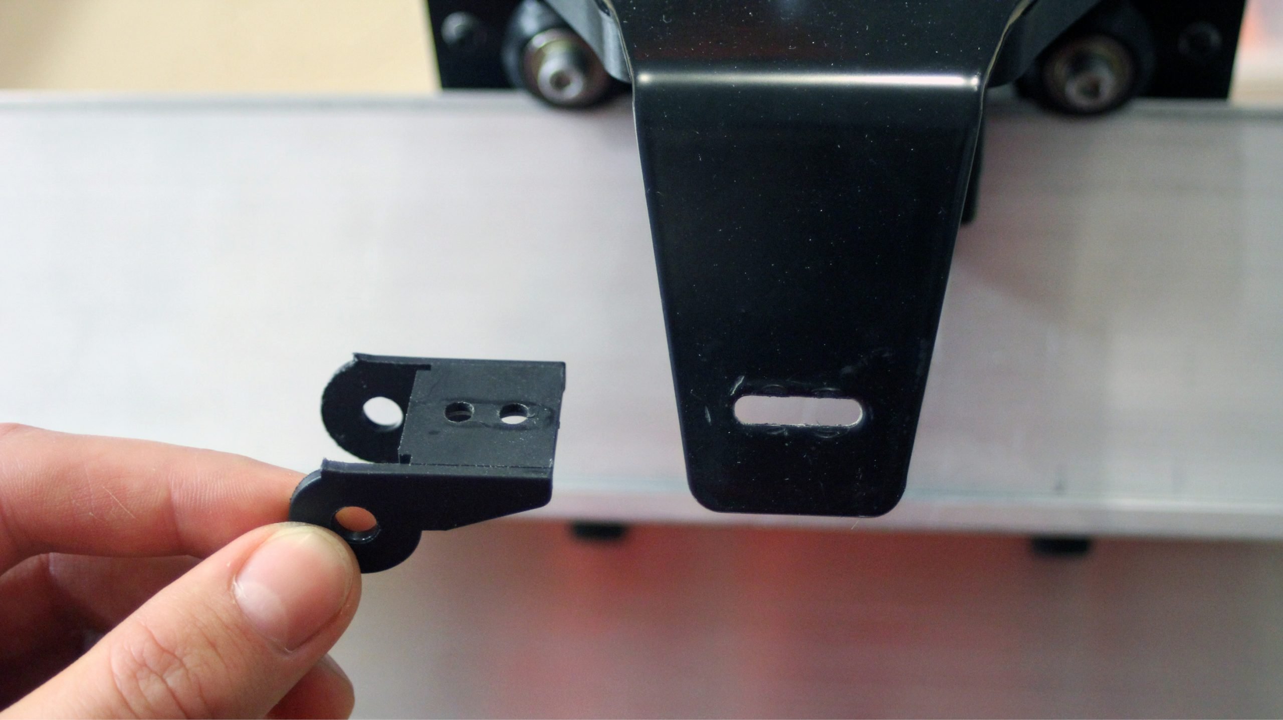
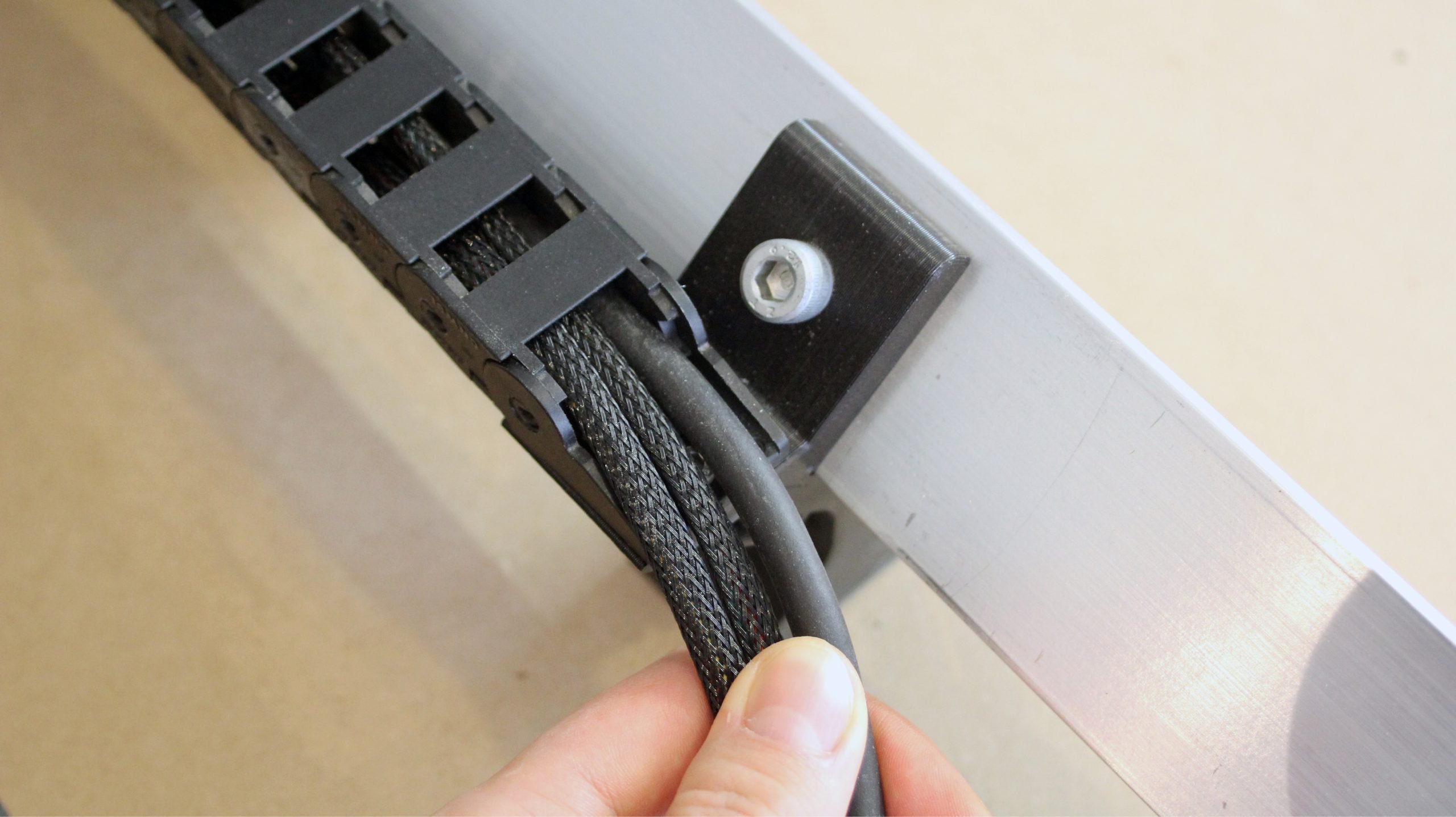
On the back-left side of the X-axis rail, you’ll find a hole to secure another drag chain link. You should only need one bolt to secure the pin-type end link using the tapped hole. If your hole is not tapped, use an M4 nylock nut on the other side to secure the part.


Lastly, attach the final drag chain end link onto the plastic ‘arm’ of the Z-axis mount using another pair of M4 bolts and nuts. Note the direction the link is facing before installing it.

Next, we’ll be removing a couple of links on the drag chain. To do this, put your hands on either side of the link you want to break, then twist and pull them apart to disconnect. Set aside the remaining, unused links. They can come in use if you’re planning on upgrading to a larger sized LongMill later.
12x12
On the 12×12 LongMill, both chains need to be shortened to about 24 links long. This is a little over half the length of the existing drag chains so it’s easiest to just fold it in half and add a couple links onto the halfway point.
12x30
On the 12×30 LongMill, only the Y-axis drag chain needs to be shortened to about 24 links long. This is a little over half the length of the existing drag chain so it’s easiest to just fold it in half and add a couple links onto the halfway point.
30x30
In the case of a 30×30 machine, remove 15 links off of the Y-axis drag chain, and none off of the X-axis drag chain. This will make it the correct length to mount at both ends when re-attached. Make sure to keep track of which chain is the shorter one so that you can re-attached them onto the correct axes.

We’ll then start to unclip the tabs that hold the wires in the drag chain (pictured). These tabs are designed with clips on both side so that they can be removed to allow you to insert and remove wiring inside the drag chain. The clips on the tabs are quite strong, but the LongMill wrench had a taper that can assist you with popping them open. Leveraging the tabs open by sliding in a flat head screwdriver or a long Allen key also works quite well.
If you plan on adding more wiring into the drag chains in the future, we recommend removing every other cover tab as well. The wire will be held in just as well but opening and closing them will take half the time. You can stick the extras into a baggy to save for later if you wish.


At this stage, it’s a good idea to grab the router you’ll be using with your machine. We’ll show these steps using the RTMakita RT0700 / RT0701 trim router that we recommend. Also, grab the motor wires from the motor box while you’re at it.
!! IMPORTANT NOTE: when using the Makita 0700 / RT0701 you won’t need to use the router base, just the main router body. The package also comes with two wrenches to tighten and release the collet which holds the cutting tools in place. You’ll see a red button near the collet nut, but please refrain from using this red button. Using this red button can stress the router body and occasionally cause the whole body to crack open.

To mount your router, simply loosen off the two front bolts until you can fit the router in the mount, then tighten back up to secure it. You can adjust the height later if needed.
We recommend going back and forth between the two bolts to keep them parallel; and make sure not to over-tighten them. It’s also best to face your router power cable towards the left side (pictured) since the dust shoe hose port sticks up on the right side of the router mount.

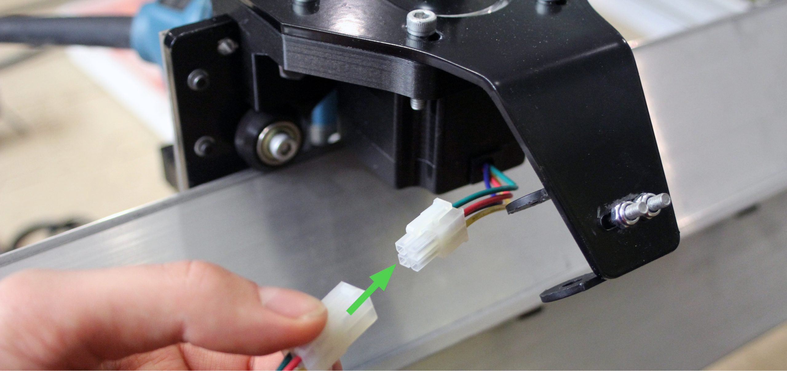
Grab a motor cable and connect it to the Z-axis NEMA 23 motor. If you have a cable bundle on your motor then the motor cable will still attach in a similar manner. The connectors can only go in one way, so find the orientation where the connector attaches with ease.
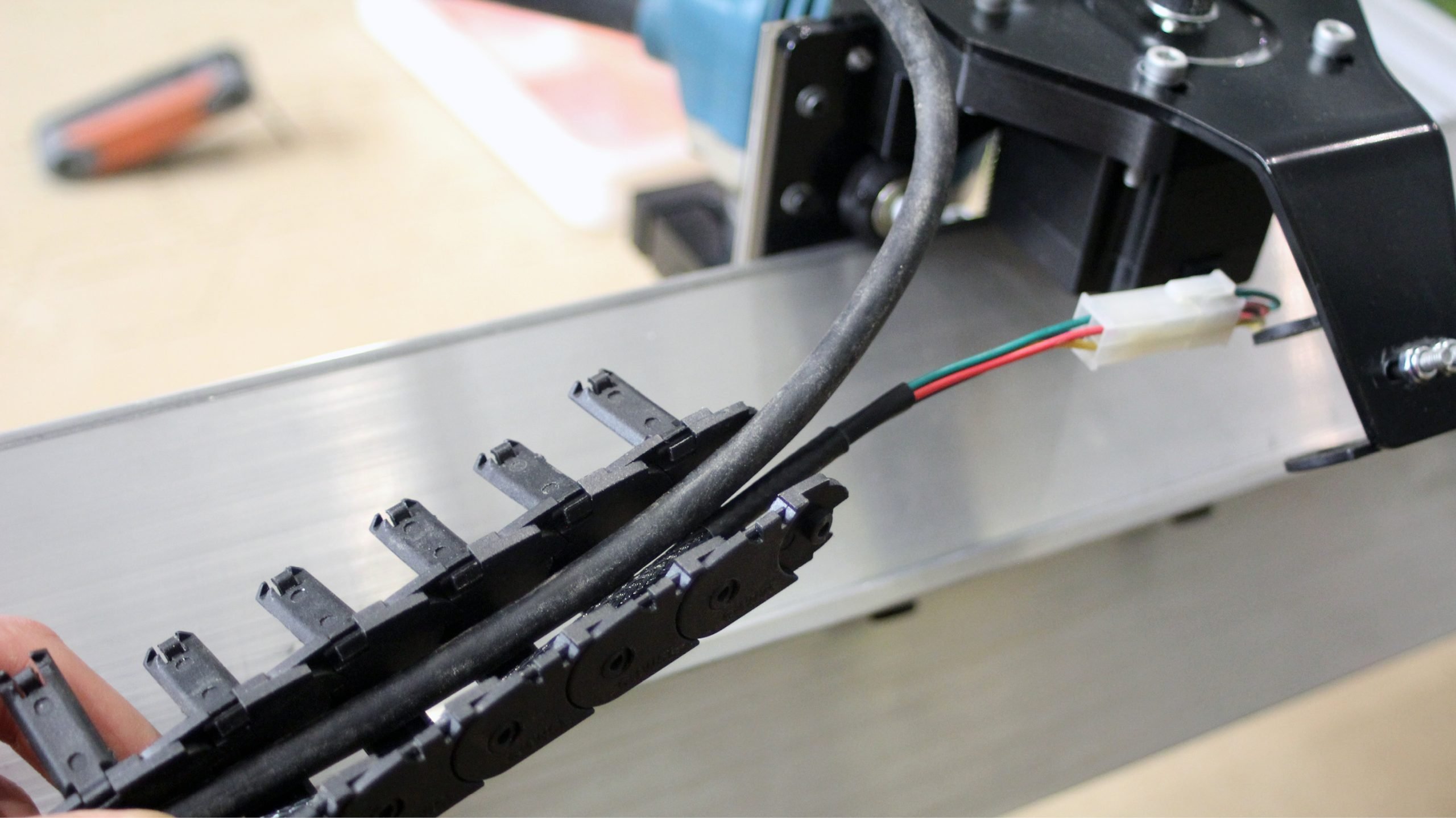
Grab the drag chain for the X-axis (the longer one for the 30×30) and seat the Z-axis motor and the router wire into the drag chain. Make sure that you have the correct end of the drag chain (with a pin-type link). This way, you’ll be able to connect it to the mounted end link (pictured), and it’ll bend in the right direction against the X-axis. You can start to re-clip the tabs in place.

Swing the drag chain and clip it onto the end link attached to the X-axis rail. Pull the wires through.
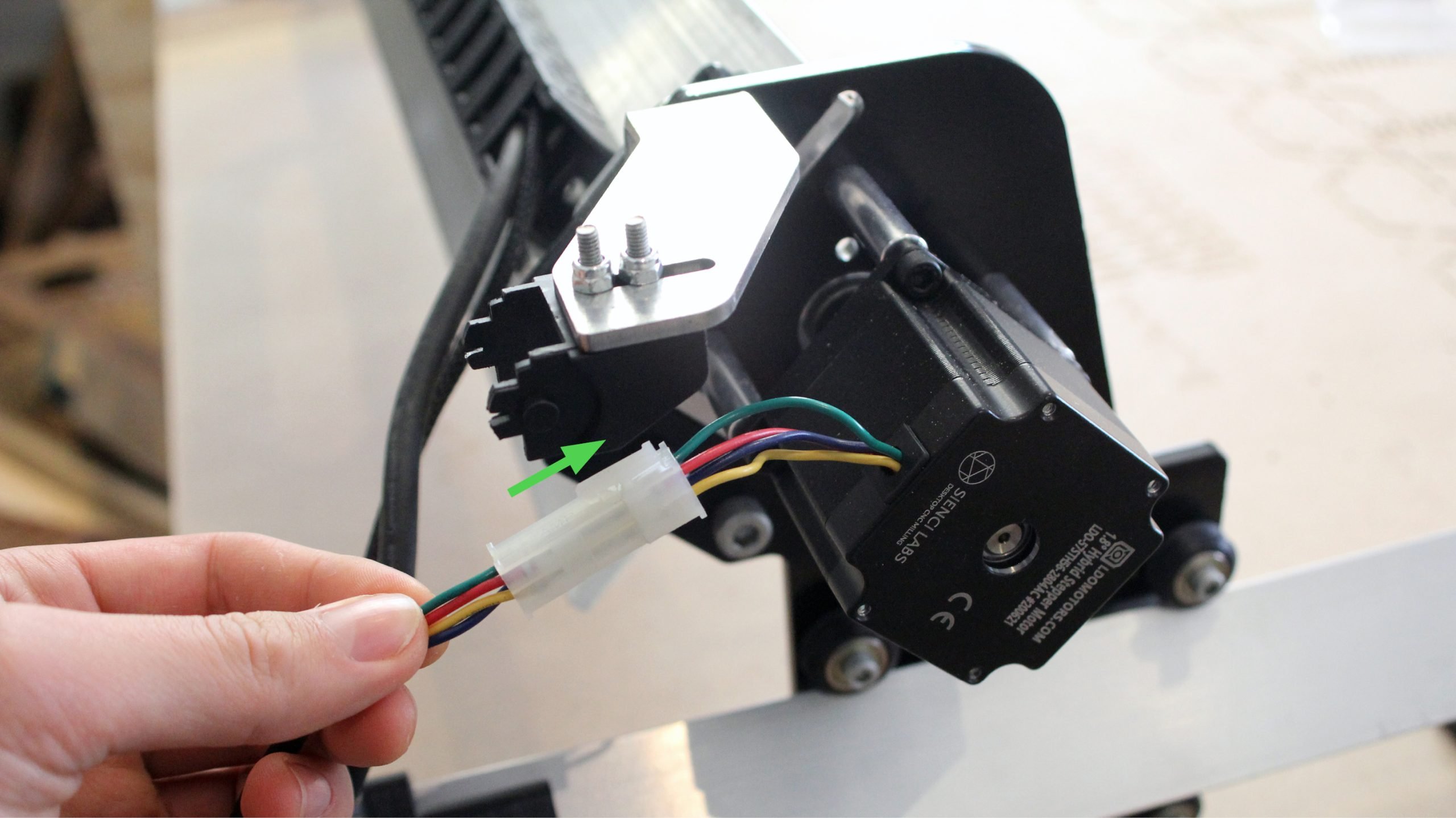
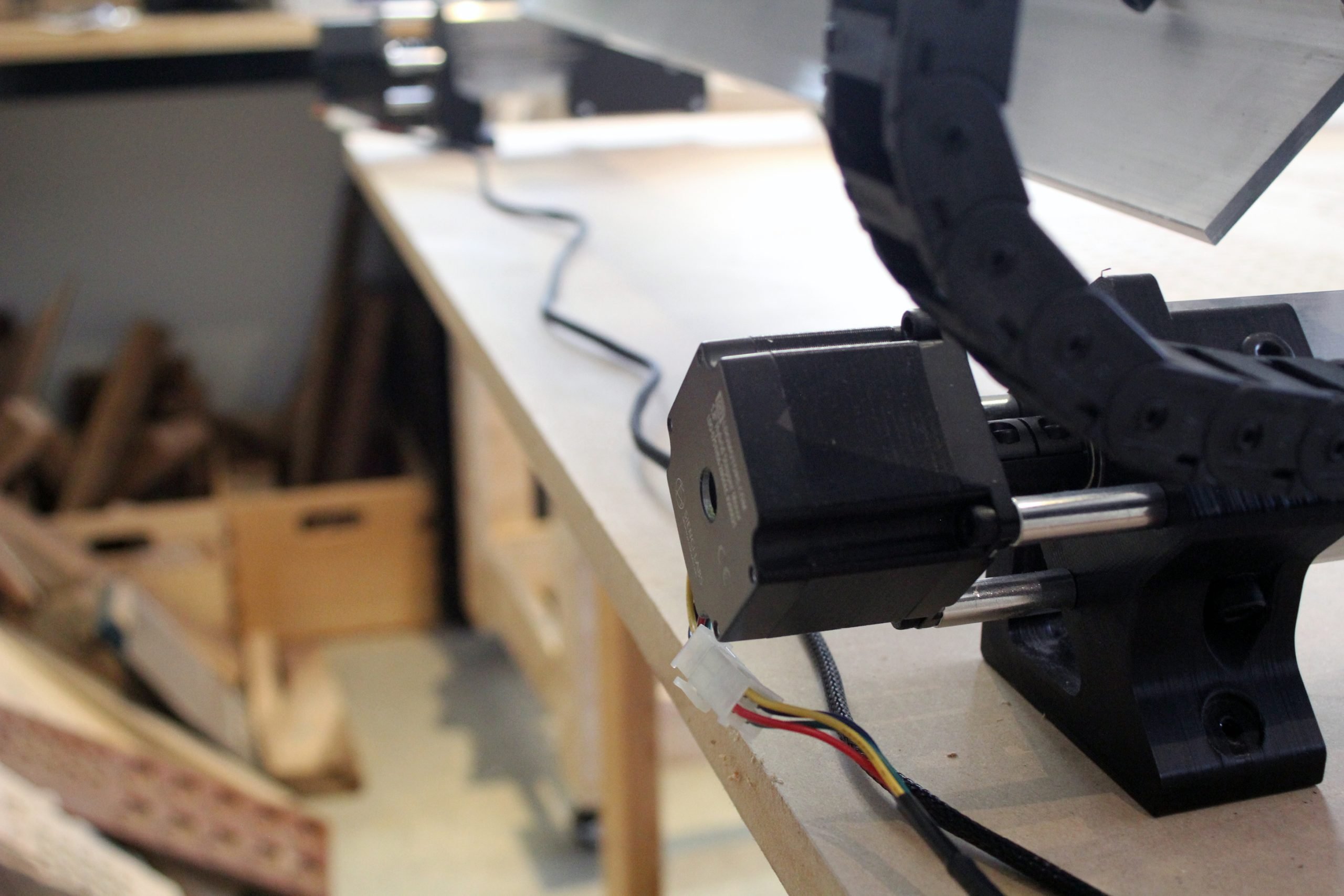
Attach a motor cable onto the X-axis NEMA 23 stepper motor.
Take the cable from the X-axis and Z-axis NEMA 23 stepper motors as well as the router cable and insert it into the Y-axis drag chain. Clip the tabs in to secure the wires. Ensure the drag chain is facing the right direction (with the hole-type link, pictured) to fit into the correct end links.

Clip the both ends of the drag chain into the previously mounted end links on the Y-gantry and the drag chain foot.
Now plug in the cables for the motors on the two Y-axis NEMA 23 stepper motors.
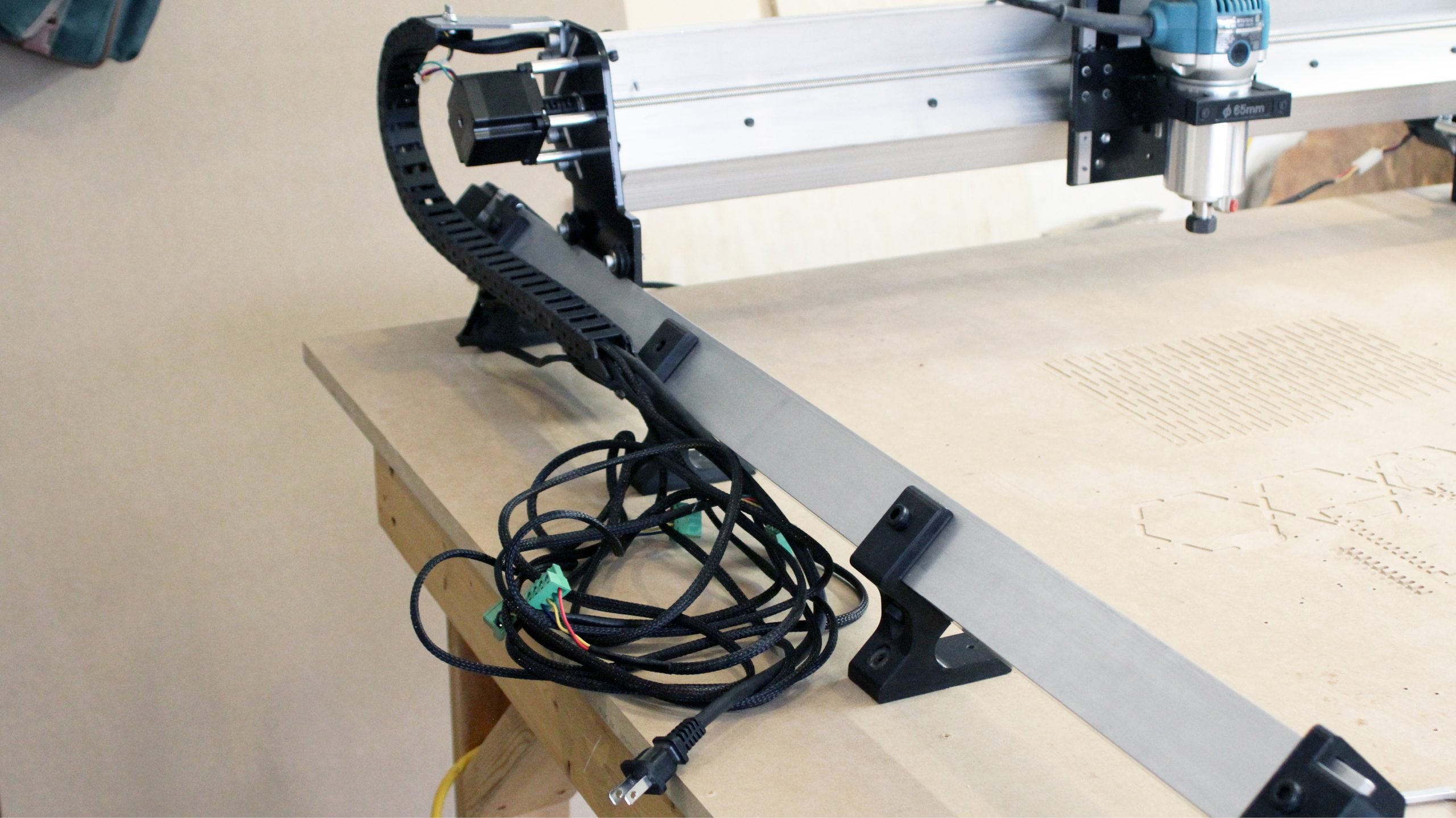
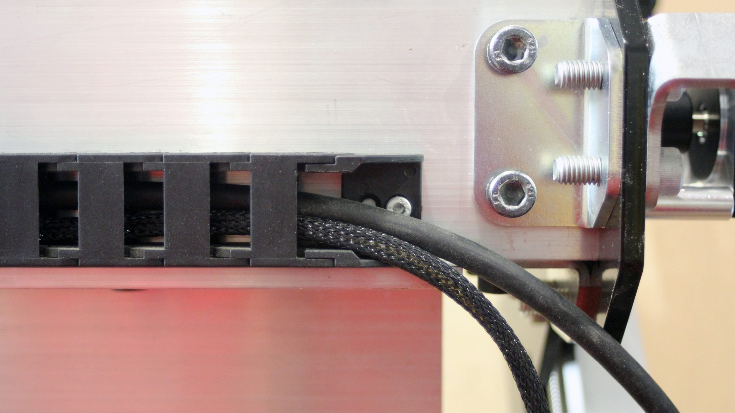
Bring the cables around to the left of the machine and slot them into the wiring cutouts in the drag chain foot.
With all of the wiring coming in from the left, the machine wiring is now be complete.