
The LongMill electronics come pre-assembled and are pretty much ready to go out of the box. However, we recommend double-checking a few things before powering-on.
DC power supply connector polarity and E-stop connector
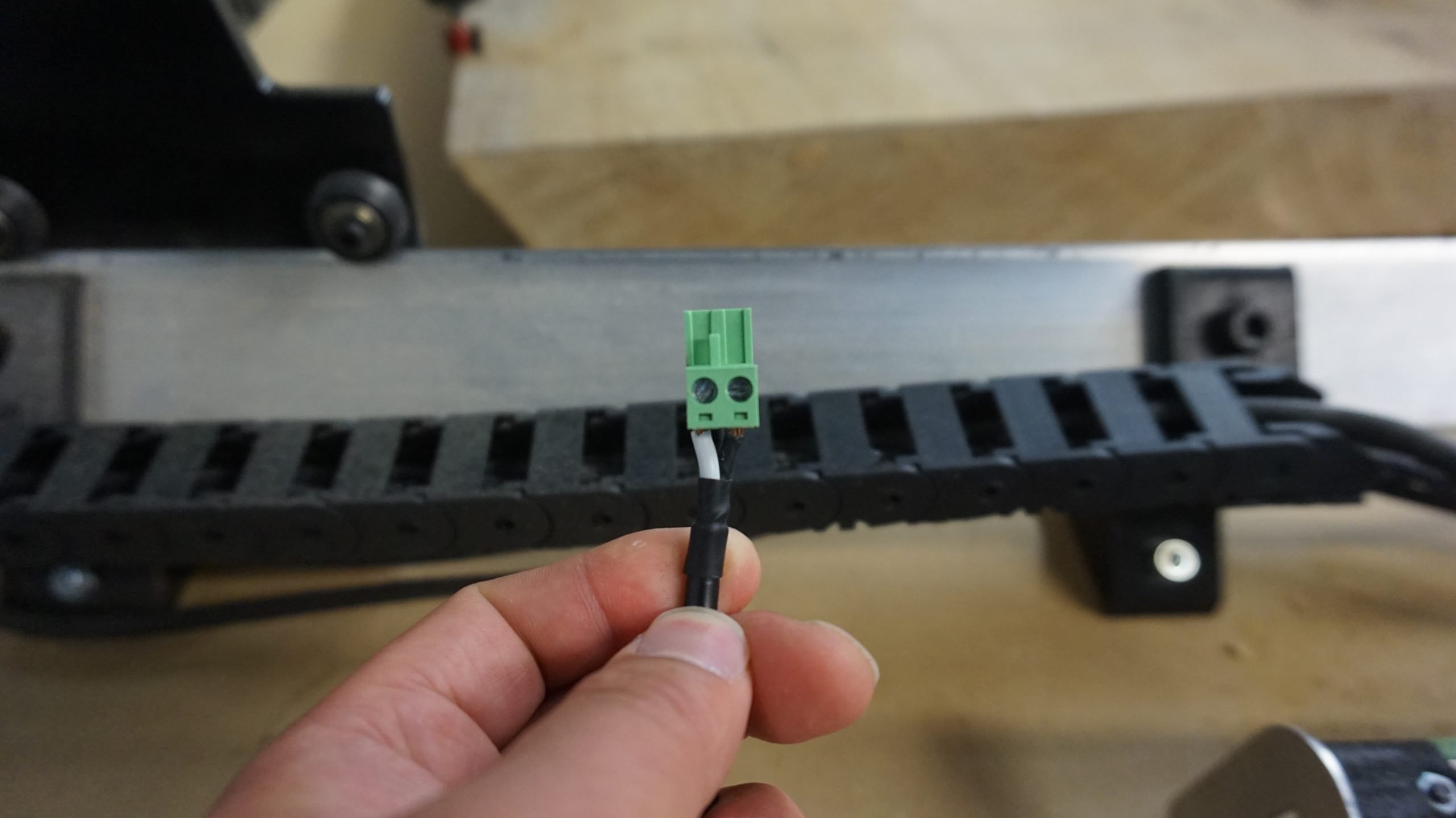
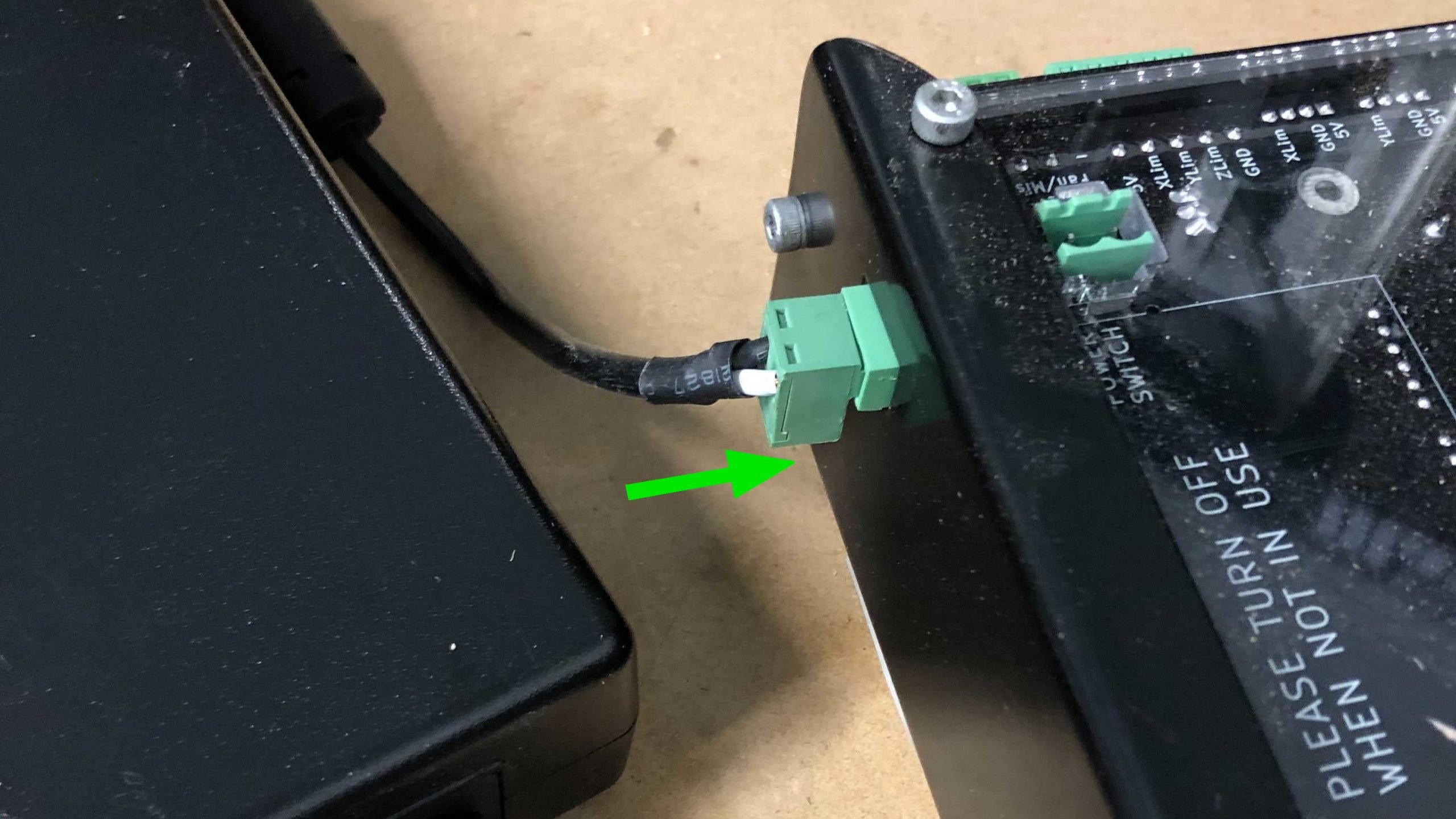
It’s important that the connector coming from the DC power brick has a white or red wire on the left side and a black one on the right when the screw terminal is facing you (as pictured). Both this connector and the connector coming from the E-stop should have the wires attached very securely. The order of the wires going to the E-stop connector don’t matter.
Check that the wires are connected appropriately by tugging on them. Secure them using the screw terminals and a flat head screwdriver if they’re loose or disconnected.
Motor connector wiring
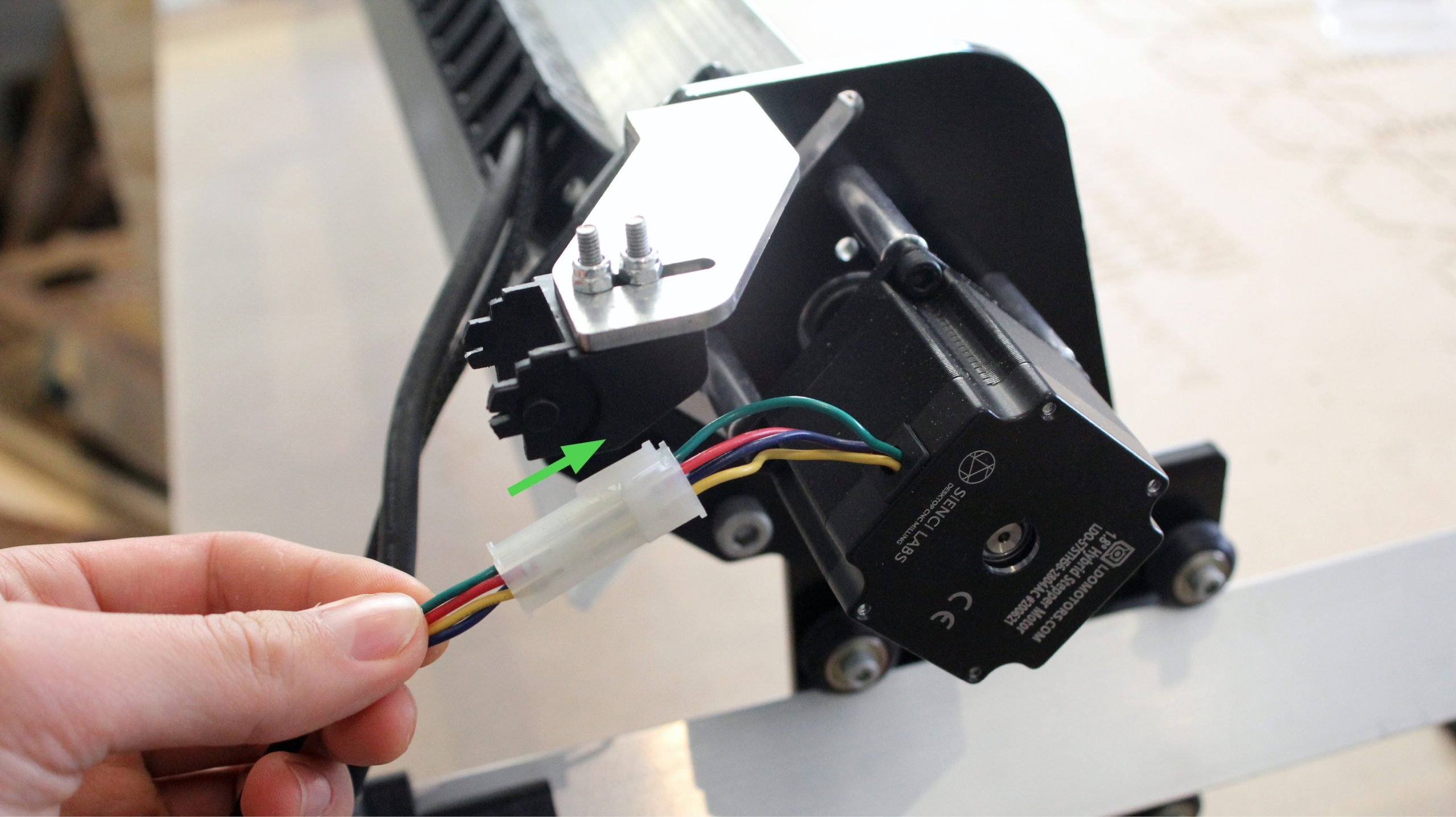
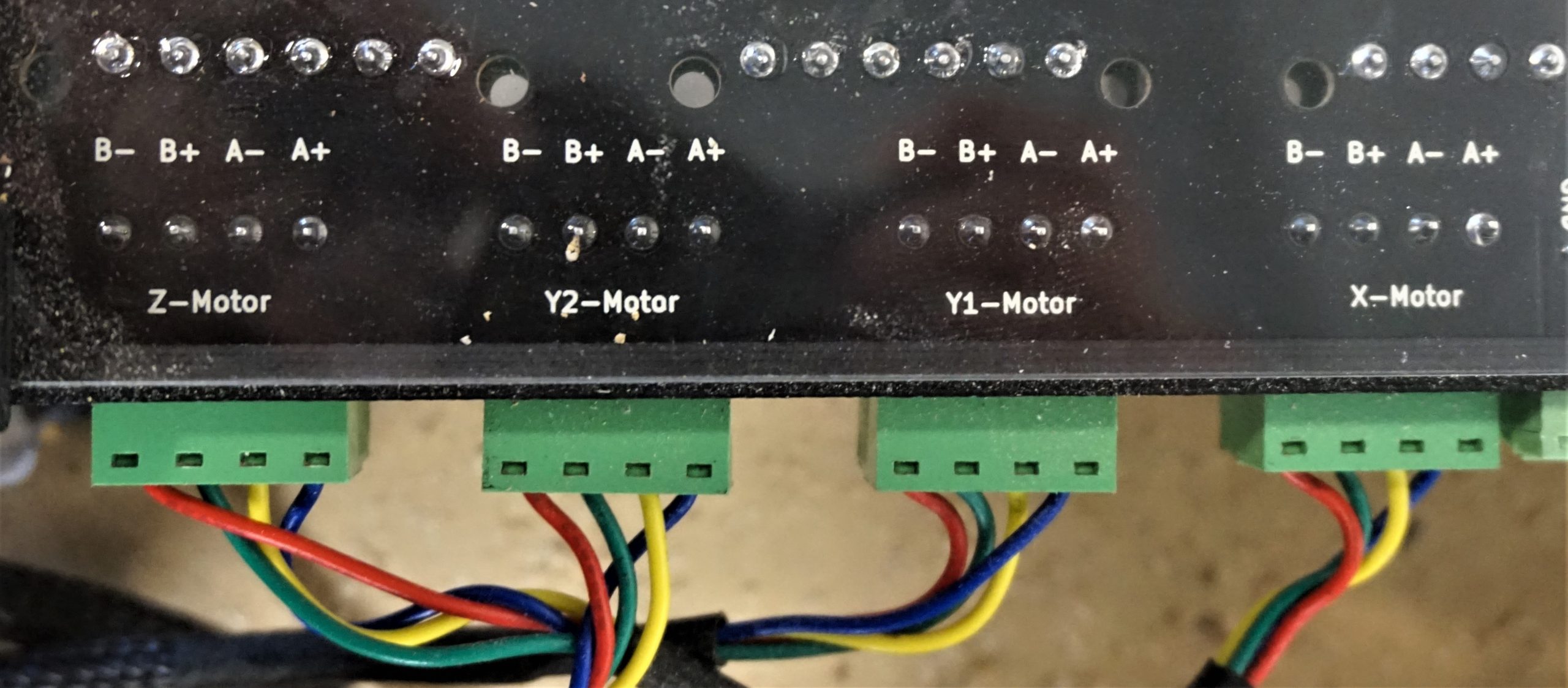
The wires, looking down from the side with the screw heads, should be, from left to right, BLUE, YELLOW, GREEN, RED (pictured). Check if the color pattern on all four of your motor wires is correct and re-arrange them if needed. As previously, also check that the wires are connected securely to the connector.

While you’re at it, double check that the motor-side, white connectors on each axis are pushed all the way into the motor housing to ensure a good connection. If these connectors are sitting too loosely, then they can cause issues later on since the motor won’t move as expected.
Properly seated DIP switches
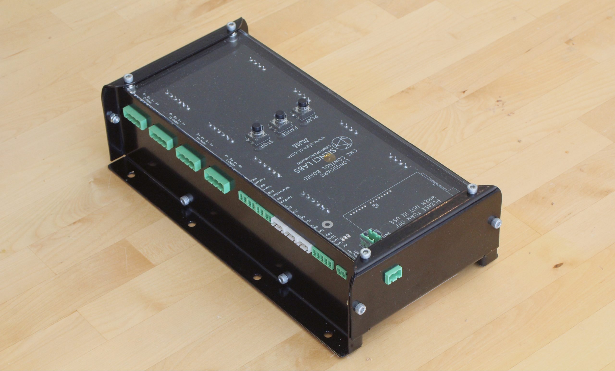
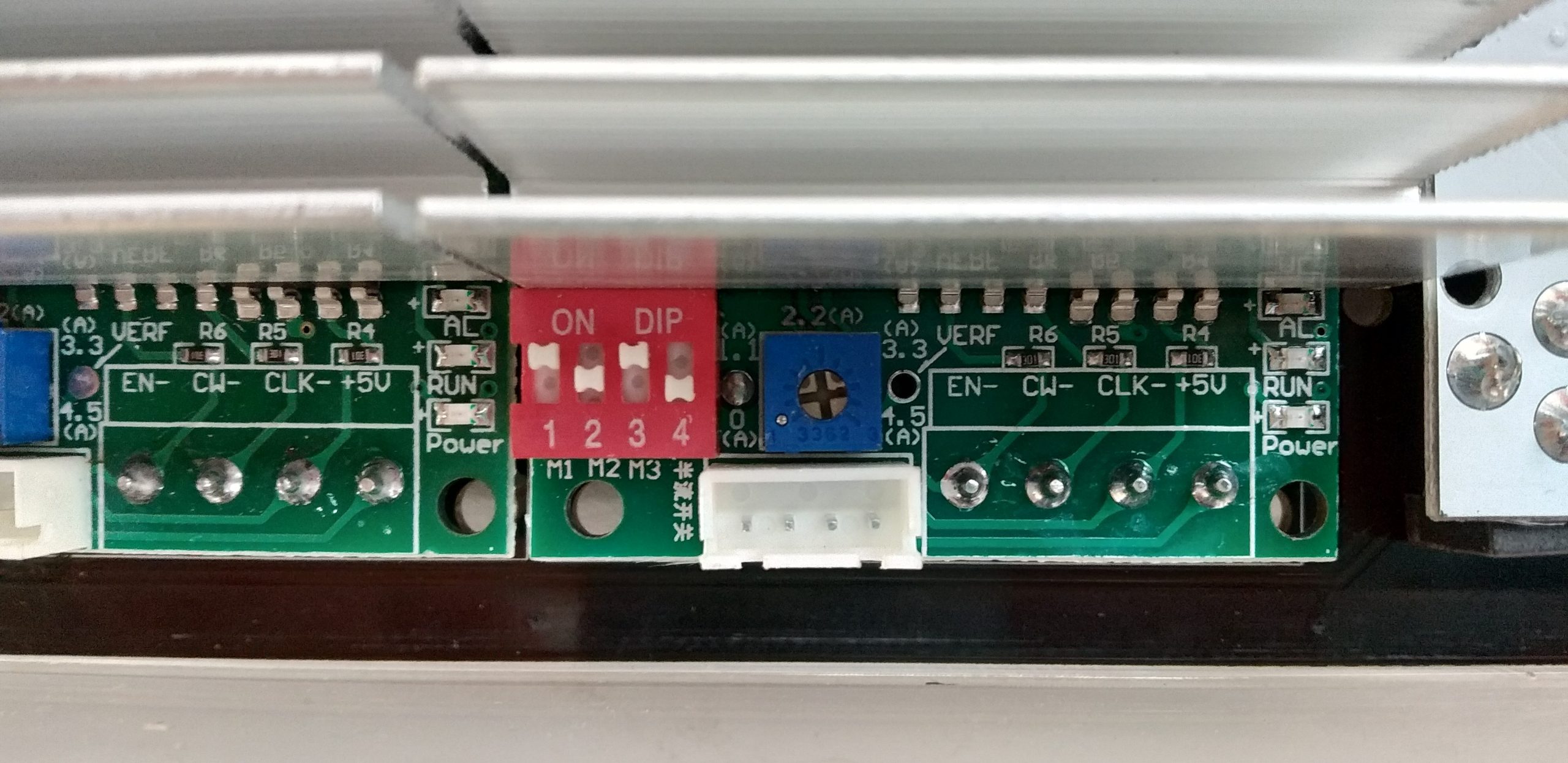
Looking at the underside of the control box, you should notice four red switch blocks on the circuit board through the slots in the steel (pictured). These are a way of toggling how the motors are controlled by their respective motor controllers, where the slots in the steel have been made wide enough so that you can reach in with a small flat head screwdriver or an Allen key to adjust these switches without dissembling anything.
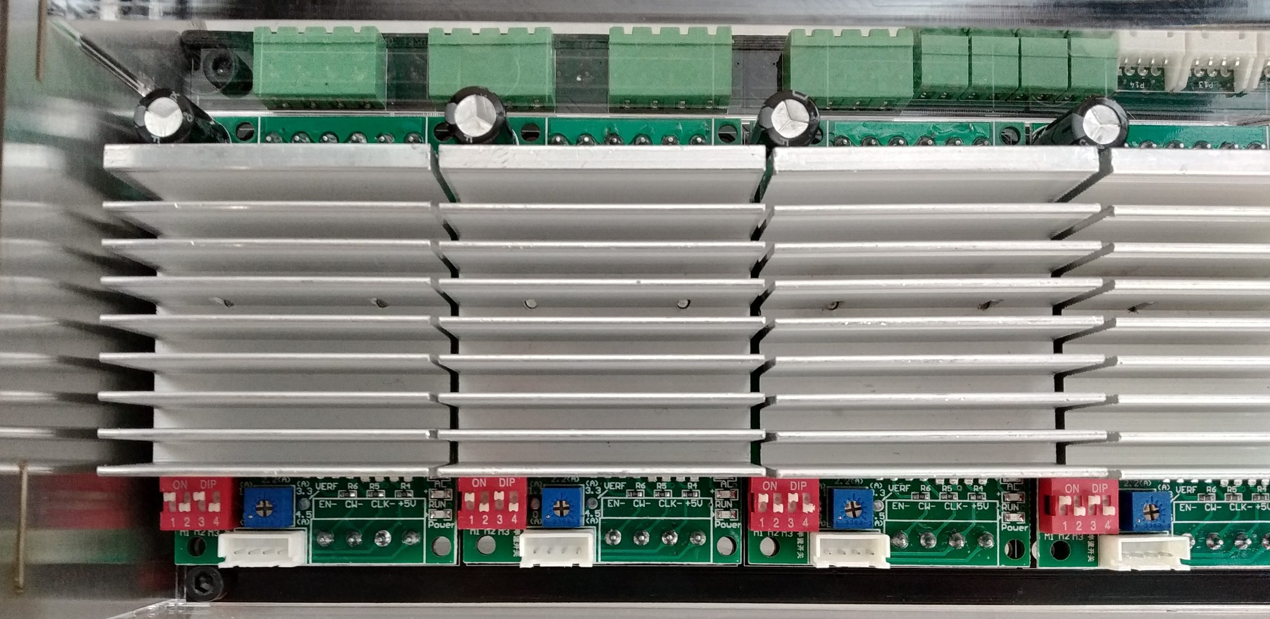
These DIP switches normally look like they’ve been properly switched when in reality they’re ‘floating’ between the up and down positions, as is the case for switch 2 in the picture below. Because of this, it’s a good idea to push every single switch into it’s correct position before moving on to the next step, putting switches 1 and 3 into the ‘up’ position and switches 2 and 4 into the ‘down’ position (pictured).
Plugging in the motors and power supply
With these checks done, start by connecting the motors. Track each cable from each motor to its corresponding green connector and connect it to the board. The fit of these connectors is tight but you need to be sure to push them ALL THE WAY in so that there is good contact between the plug and the connector. Each plug on the board is labelled on the top (note that there isn’t a difference between the Y1 and Y2 plugs, the Y-axis motors can be connected to either of them).
Next, plug the connector coming from the power brick into the rear of the LongMill’s control box (pictured); wait until after it’s plugged in before plugging the other power supply cable into the wall. A green LED on the power supply brick should light up to indicate that it’s receiving wall power.
Now, connect the emergency stop button to the control box via the connector on the top. You should be able to find your E-stop button (pictured on the right) in a bubble wrapped bag the #3 top carton. Turn it on by rotating the button clockwise. You should see a red light on top of the box light up to confirm that everything is receiving power.
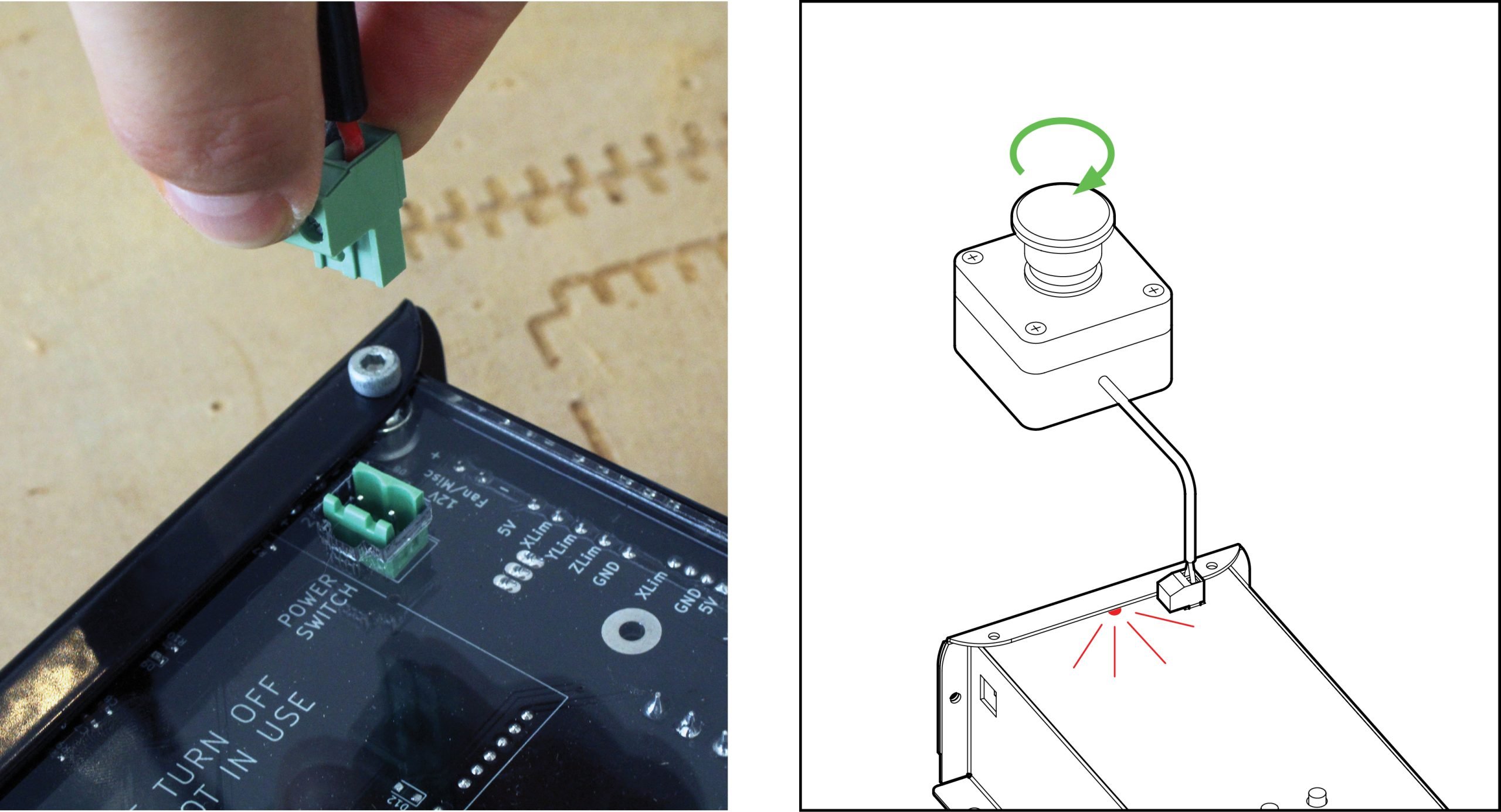
Once you’ve checked that the lights are turning on, press the E-stop button to turn it back off.
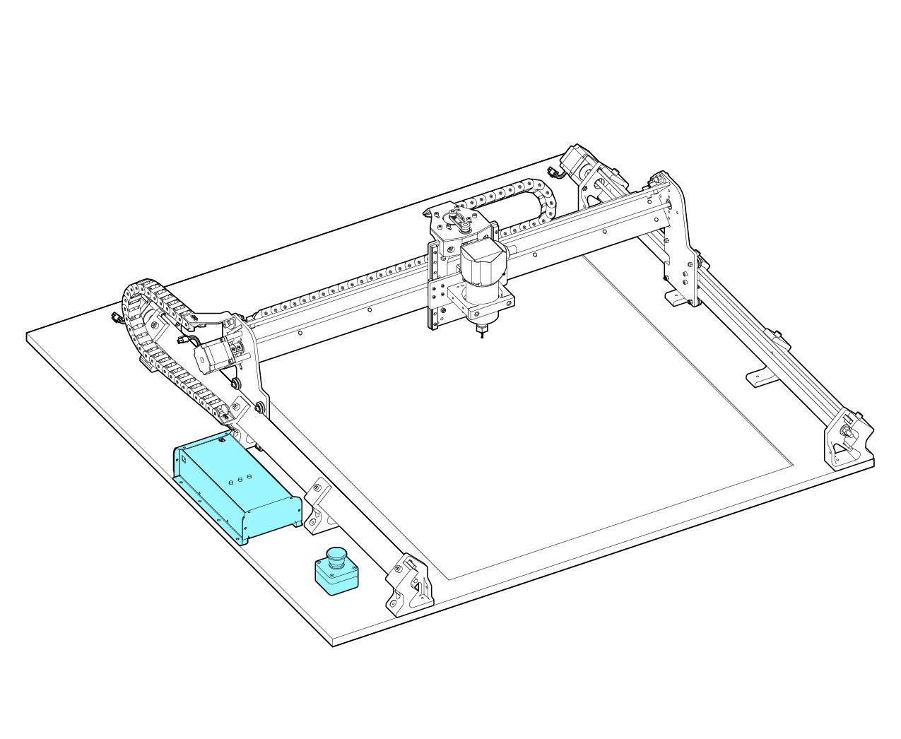
A note on the control box is that it will be limited in it’s placement due to the length of the Z-axis motor cable. If you don’t think you’ll be using the on-board control buttons feel free to mount the box out of the way – the basic operations can be controlled via a USB cable and the E-stop. If you wish to place it further from the machine, extending the wires for that cable is quite straightforward either through the use of a soldering iron or through crimp-able wire extenders.
Connecting the LongMill to your computer
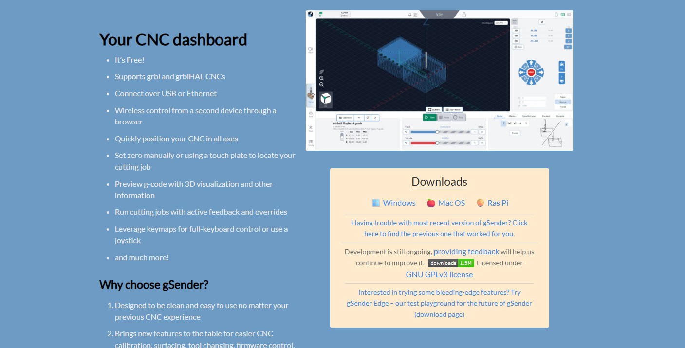
To manipulate your LongMill and send it files, you’ll need a g-code sender which acts as the control software. We recommend using gSender, which is what we’ll be using to show the next couple of steps and in the remaining part of the assembly.
gSender works with any operating system: Windows / PC , Mac, Linux, and more. If you are not sure which type of Windows you are using, you are most likely using a 64 bit computer. You can try both and see which one starts.
You can download gSender here: https://sienci.com/gsender/ Choose the download for you, and if you get stuck you can always reference here for more help: https://resources.sienci.com/view/gs-installation/
Once you have gSender installed, go ahead and run it on your computer. One way is to double click the shortcut on your desktop.

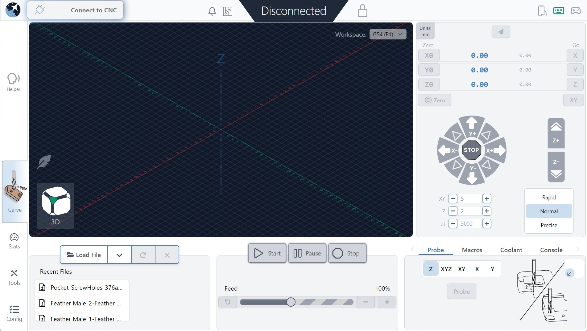
You should be greeted with a screen that looks like this. It can take several extra seconds to load if you have Microsoft real time virus protection on your computer. This scan delay should only happen the first time you turn on your computer.
Now connect your computer to the LongMill control box via USB.
Note: Your computer will automatically install drivers for the Arduino at this point if they are not already on your computer (can take a minute or two). If you try to connect your machine but you cannot, you may need to manually install the drivers. You can do this by installing the Arduino IDE which will install the drivers during the installation, or you can follow the instructions on doing them manually for Windows.


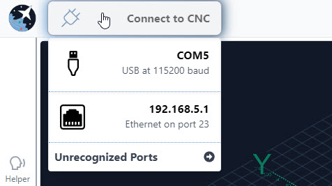
Once that is done, hover over the Connect to CNC button at the top left corner of the screen and click the first option. Sometimes there’s more than one port available, so you can either unplug the other items you have plugged in, or you can try connecting to each one to see which one is your LongMill (note that it’s recommended to connect this way on your first setup even if you’re planning to use Ethernet in the long-run).
Once you’ve selected the port, your machine should be connected. If your machine is powered on, you will usually hear a gentle hiss and a thump noise when the machine connects which is a nice audible confirmation. If you don’t hear that sound, make sure you have released the E-stop so power is going to your machine – indicated by and orange power light on your control box.
After a moment you should see the plug icon turn green with a checkmark, the status bar at the top, middle change from Disconnected to Idle, and all the controls in the app become coloured indicating that they’re ready to be used.
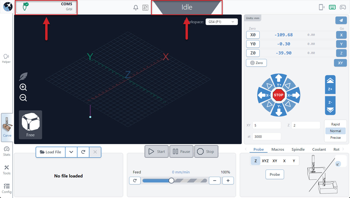
You can now try playing around with moving the machine. You can jog the machine in the direction you want within the “Jog Control” section on the right side. It’s alive!
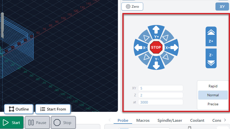
You can choose the amount that the machine will move in the XY directions by changing the “XY move”, the amount in the Z direction with “Z move”, and the feed rate / speed of movement with “Speed.” gSender has defaults for large, medium, and small movements that you can switch between by pressing the “Rapid”, “Normal”, and “Precise” buttons.
Also, if you prefer inches instead of millimeters you can also switch over using the gear icon on the top right of the gSender window.
For now, moving the machine around will be important for when we mount the machine to the wasteboard. On to the table mounting!