
You can use an IOT relay to automatically control power to your router, vacuum, lighting, or other AC power systems when you have a job running. The setup process consists of:
- Wiring up the IOT relay
- Preparing your g-code to control the relay
This IOT setup method is written for the LongBoard controller and was inspired by the work of Max C., Mark D. and other LongMill community members! If you’d like to see Max’ full original document, you can download it here: IOT Relay.doc
Hardware
Parts needed:
- IOT relay
- We’ve tested the IOT Relay from Digital Loggers, but it can be found on a few sites such as DigiKey, PwnCNC, and Amazon. Find more info here: https://www.digital-loggers.com/iotfaqs.html.
- Includes surge suppression, debounce, and a safety breaker
- Consists of 4 outlets – x1 Always On, x1 Normally On (NO), x2 Normally Off (NC)
- Can also be controlled by a standalone Arduino or Raspberry Pi
- 2-position female terminal block connector (x2)
- One will come already plugged into the IOT relay, the other plugged into the LongBoard
- Same as the green connector used for the touch plate
- 3.81mm (0.15″) pitch
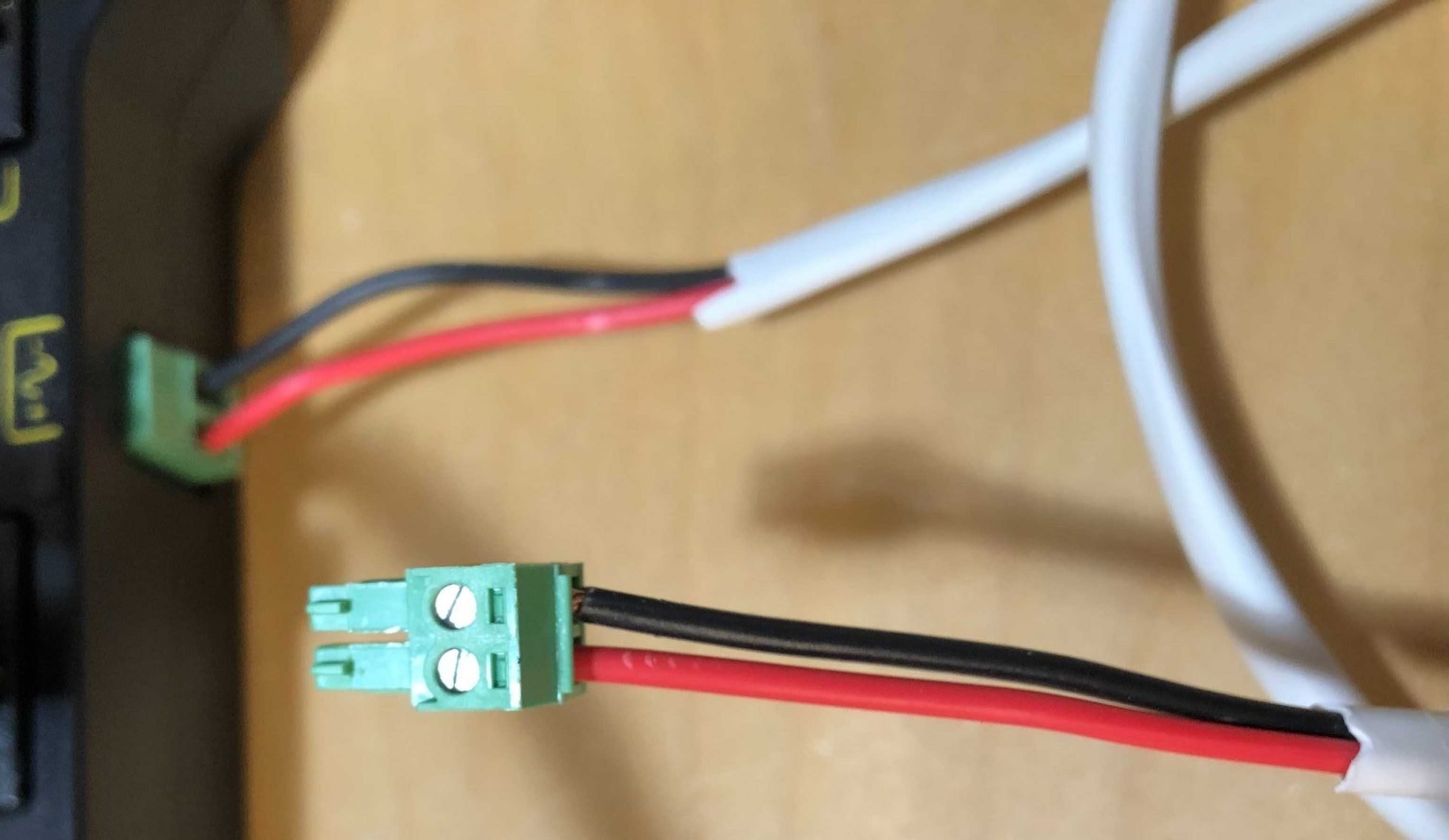
- Some spare 16 AWG wire (see picture)
- This is the same size as what’s used for the LongMill E-stop
- Ideally use wire with the red and black bound together, in whatever length is needed for your setup
Installation
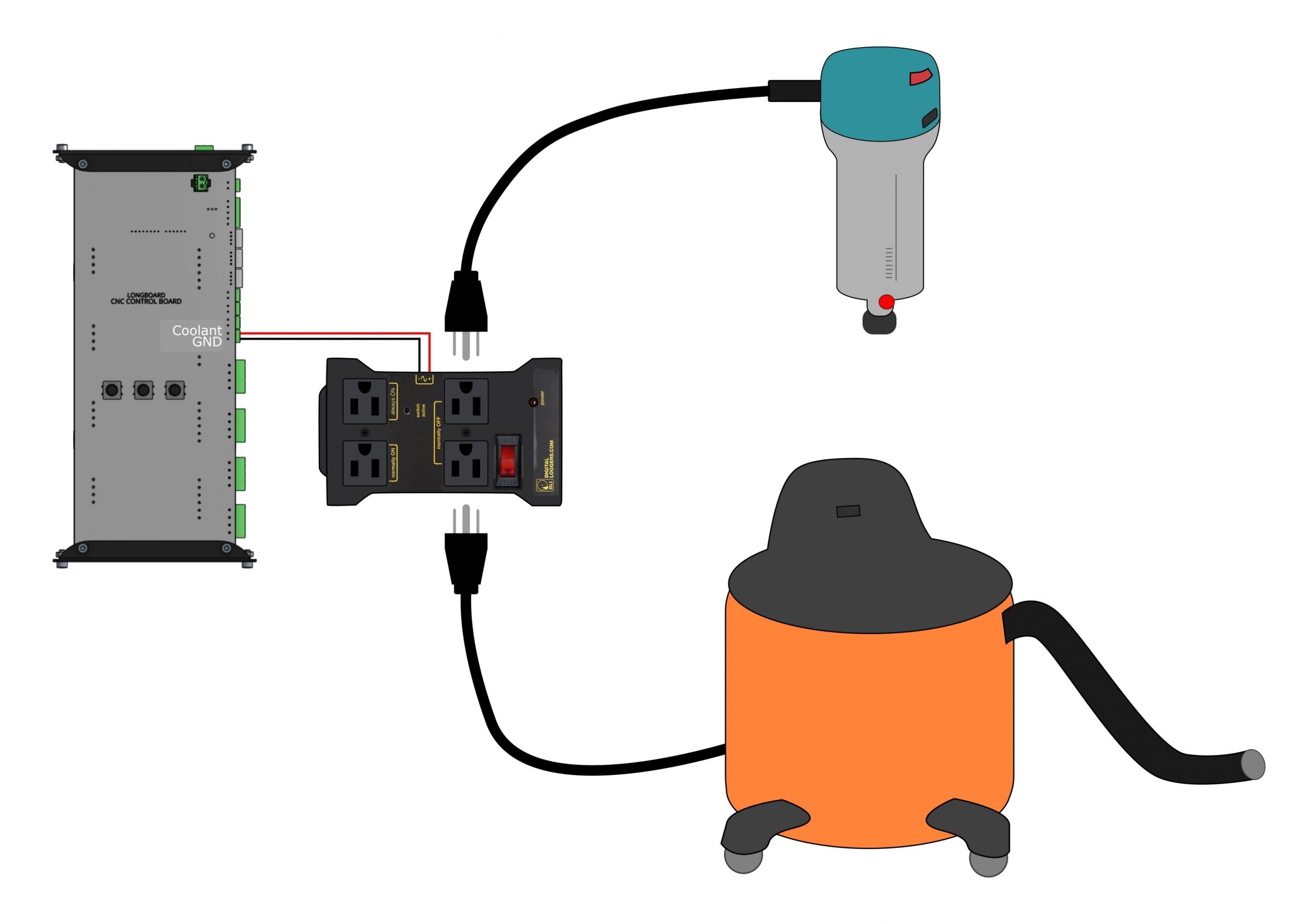
- Take out the green connector from the IOT relay and loosen the flat-head screws on the connector.
- Wire this connector so that the wires match up with the labelling on the IOT relay: red wire to the positive (+) and black to the negative (-). Clamp down the wires using the flat-heads on the terminals.
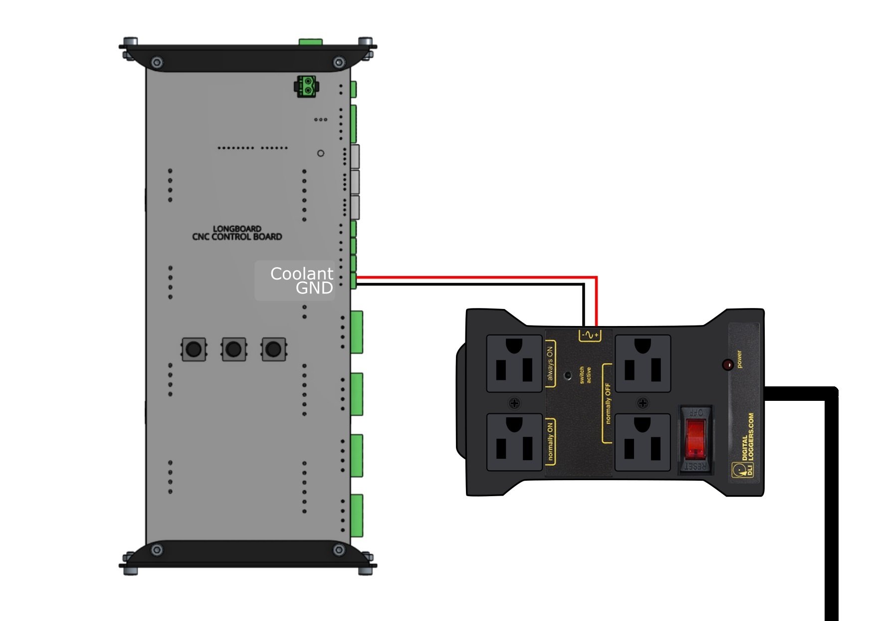
- Do the same on the other end, this time matching the red wire to “Coolant” and the black wire into “GND”, clamping the wires firmly into place.
- Finally, use the power cord provided with the IOT relay to plug it into a nearby outlet (if you plan on drawing reasonable current through the relay, consider using an outlet that’s on a breaker separate from your CNC machine to reduce line noise).
Testing
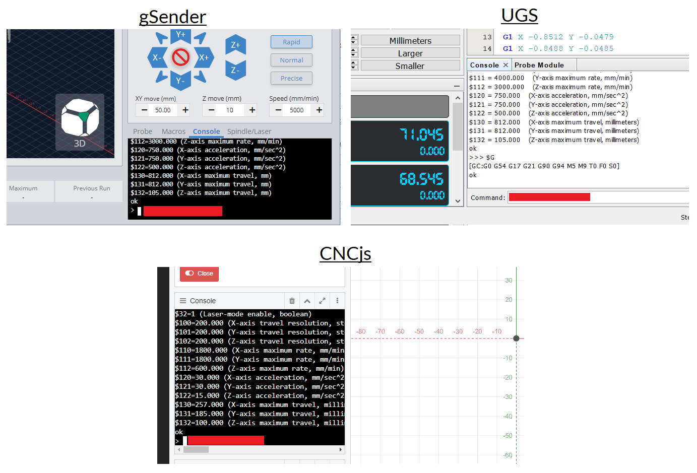
Now’s a good time to quickly verify that everything has been hooked up correctly. To test the relay, we’ll be connecting to our LongMill via a g-code sender such as gSender, UGS, or CNCjs like we normally would and keep an eye on the red “power” light on the relay. Whichever sender you use you’ll want to find the “Console” input area (shown by a red box), and type the following text:
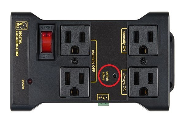
- M8, then press the ‘Enter’ key to send – this should activate an audible click from the IOT relay and you should notice the ‘switch active’ light illuminate.
- M9, then press the ‘Enter’ key to send – this should also produce a click noise, this time turning the ‘switch active’ light off.
If you’re not seeing the results you expect, double-check you’ve got your wires running correctly and the connectors are plugged in all the way to the relay and the LongBoard.
If everything is behaving as expected, you’ll now be able to test with the relay controlling whatever peripheral you’re planning on hooking up (vacuum, router, etc.). Note that the IOT relay is built to handle 0-8A with 18AWG power cords and 0-12A with 16AWG cord.
- Be sure you’ve sent M9 to your g-code sender and the relay power light is off.
- With the IOT relay toggle switch set to “OFF”, plug in your external AC device. You’ll normally want to use the “Normally Off” outlets since these turn ON with M8 and OFF with M9, meanwhile the “Always On” outlet always provides continuous power and the “Normally On” outlet turns OFF with M8 and turns ON with M9.
- Safely toggle the power switch on your external device (router, vacuum, etc.) to be ON. They should show no sign of power at this point.
- Safely toggle the IOT relay switch to ‘RESET’. There should still be nothing occurring.
- Send again an M8 command in the g-code sender while your finger is on the red switch of the IOT relay in case something goes wrong. After sending the command your external devices should now power on.
- Power everything back off by sending M9.
G-code
With everything working correctly, we now need to make sure these M8 and M9 g-code commands exist within your job files to signal the IOT relay on at the start of a job and off at the end.
The easiest way to do this is to manually insert this code yourself. To do this, open your g-code in a text editor such as Notepad and:
- Start a new line at the top and type in “M8”
- Scroll to the last line of the code, start a new line and type in “M9”
- Save the g-code file with a new name in case you need to go back later to check the original
Manual replacement can get old quick, so other methods exist to automate this process every time. Firstly, some CAM programs will allow you to ‘inject’ whatever g-code you’d like before and after (referred to as the “header” and “footer” of the g-code) the main code, for example Kiri:Moto or Fusion360. If you set up your CAM program to put M8 in the header and M9 in the footer then those commands will now always be there for any project you design and output into g-code.
Another option if you’re using gSender or CNCjs is to set up custom ‘Events’ that will run the M8 and M9 commands for you for any g-code file that you run:
gSender
In gSender there’s a specialized area for this that you’ll find in your settings called “Start/Stop G-code” where you can type in the M8 in the ‘Program Start’ box and M9 in the ‘Program Stop’ box. Ensure these are both enabled and then they’ll run anytime you run a g-code file in gSender.
You can read more about this feature here: https://resources.sienci.com/view/gs-additional-features/#startstop-g-code
CNCjs
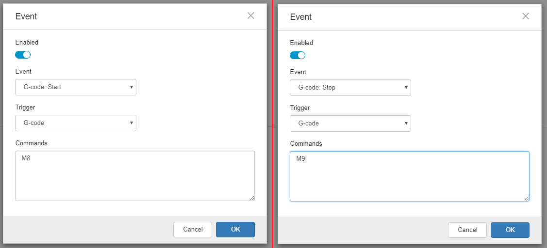
- Go to Settings (gears on the left) ➜ Events, and add a new event for the both commands
- Use events “G-code: Start” for the M8 command and “G-code: Stop” for M9
This will now ‘inject’ the M8 command at the start of any g-code file and an M9 at the end. It applies to every file you run unless you disable them.
With your relay hooked up, you’ve now got a pretty serious CNC setup! Go out and leverage this new-found power to make great things and remember to stay safe 🙂
Troubleshooting
We’ve occasionally heard of a situation where after the relay is wired up it can be enabled and disabled via the M8 and M9 commands but then when a file is run with M8 and M9 the program doesn’t run and the CNC just sits motionless. We’re still not fully certain on what the cause of this problem is but we’ve heard from LMers that increasing the gauge of wire going from the LongBoard to the relay, decreasing the distance between the LongBoard and the relay, and using a circuit breaker for the relay that’s separate from the LongMill itself are all options that have previously remedied the issue.