
Limit switches (also referred to as end stops or homing switches) are sensors that sit at one or both ends of each movement axis of a CNC to provide a few different functions. There are many different limit switch designs which broadly fall under being either mechanical or non-mechanical (ex. inductive).
In order to use limit switches, you will need to make modifications to both the electronics and firmware of the machine. For more in-depth information on the firmware, specifically the settings required to enable limit switch capability, visit the grbl v1.1 Configuration Guide.
Do I Need Limit Switches?
The LongMill does NOT need limit switches to operate and doesn’t include them by default. Many individuals are drawn to having switches by convention, but most times a limit switch exists to either:
- Define soft or hard limits* in order to prevent a CNC from damaging itself if it travels past its movement limits
- Repeatably locate the machine (homing) for jogging / work offsets, saving a job that’s gone bad, or to resume existing work done for a multi-part job
The LongMill design addresses these functions by way of:
- Being designed so that hitting the ends of its travel area causes zero damage to the machine
- In larger, more powerful machines such as VMCs and industrial CNC routers, crashing a machine can very well mean costly damage to your machine so limit switches are cheap insurance to prevent that. However, on hobby machines like the LongMill, the machine is not powerful enough to cause damage to itself, and so are not really necessary. In fact, in some cases, it can be more of a hassle as accidental triggers can ruin a project.
- Locating the machine can easily be done via the use of a touch plate
- ‘Homing’ is just the act of calibrating a CNC to a particular spot repeatably so that if, for example, you lose your CNC position due to a power outage or for a tool-change then you can find that position again using the offset distance from the calibrated point. This calibrated point can be set using limit switches but can just as easily be a touch plate or conductive geometry that a tool can touch off
With this being said, some users may still choose to integrate switches into their machine if they start to find themselves running longer and longer jobs, performing more complex cuts, or they’re looking for easier job relocation without having to keep their touch plate in mind.
*A soft limit is when there is a single switch on one side of the movement and the movement limit is defined in software, whereas a hard limit has two switches on either movement end which signal a ‘Stop’ to the controller if triggered.
Wiring Considerations
Already the LongMill controller comes with two different input spaces (a JST-XH connector for each axis and a screw terminal connector) that allows easy connection of any kind of switch. If you are intent on installing switches yourself, here are some crucial points you’re aware of:
- For limit switches on a CNC, what matters most is that the sensing happens precisely and that the accuracy deviates very little with changes in the surrounding environment, otherwise the switch might activate 2mm away when you’ve got your shed heater on but 3mm away if you open the door. Each manufacturer should provide theses sorts of details in their sensor documentation.
- It’s very important to shield and filter noise along the lines with the limit switches, as interference can cause the limits to trigger erratically. We have found that placing a 0.1uF capacitor across the input and ground for each limit helps to prevent errant triggers.
- If you are wiring limits to both ends of the axis, you can put them parallel to each other.
- All of the switches share the same ground.
Installation
In order to attach and wire your own custom set of limit switches to your setup, you will need the following:
- Soldering iron
- Solder
- Heat shrink
- 4-pin JST connectors (optional)
- 20-24 AWG copper stranded wire
- Limit switches, either mechanical or inductive
- 3x 10 kΩ resistor (for Rev 1.2 and Rev 1.3)
- 3x 0.1 mF ceramic non-polarized capacitors (for Rev 1.2)
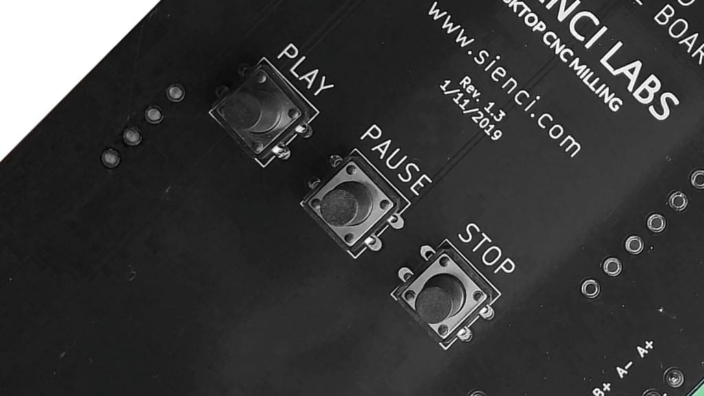
You can check the version of your LongBoard on top of your control box.
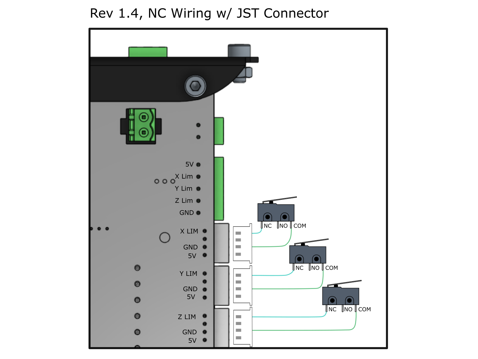
The first step is to figure out where to wire your limit switches. Each limit switch will come with 3 wires, signal, GND and 5V. They will either be bare wires or come with connectors. For switches that come with 4-pin JST connectors, you can simply plug the switches into the white connectors on the side of your control board, making sure the wiring is correct based on the type of switch you have (NO, NC, NPN, PNP). If you have just the switch and wires, use the green connectors because you can fasten down wires with these connectors.
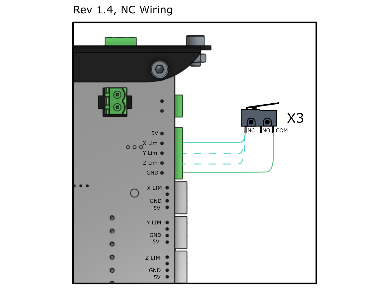
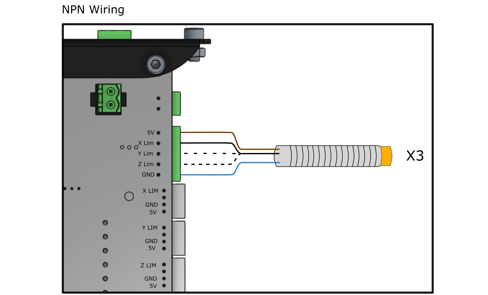
For mechanical switches, each switch must be wired to a different signal line, then to GND, as indicated in the “x3” label on the diagram. For inductive switches, each switch must be wired to a different signal line, then to GND and 5V, as indicated in the “x3” label on the diagram.
Next, you will need to extend or attach the wiring for your limit switches, and find an appropriate place to mount them on the LongMill. If you are using a different limit switch, you can create your own limit switch mounts by designing and cutting them out on the machine or 3D printing them as well. Make sure the wire is long enough to reach the control board from the machine.
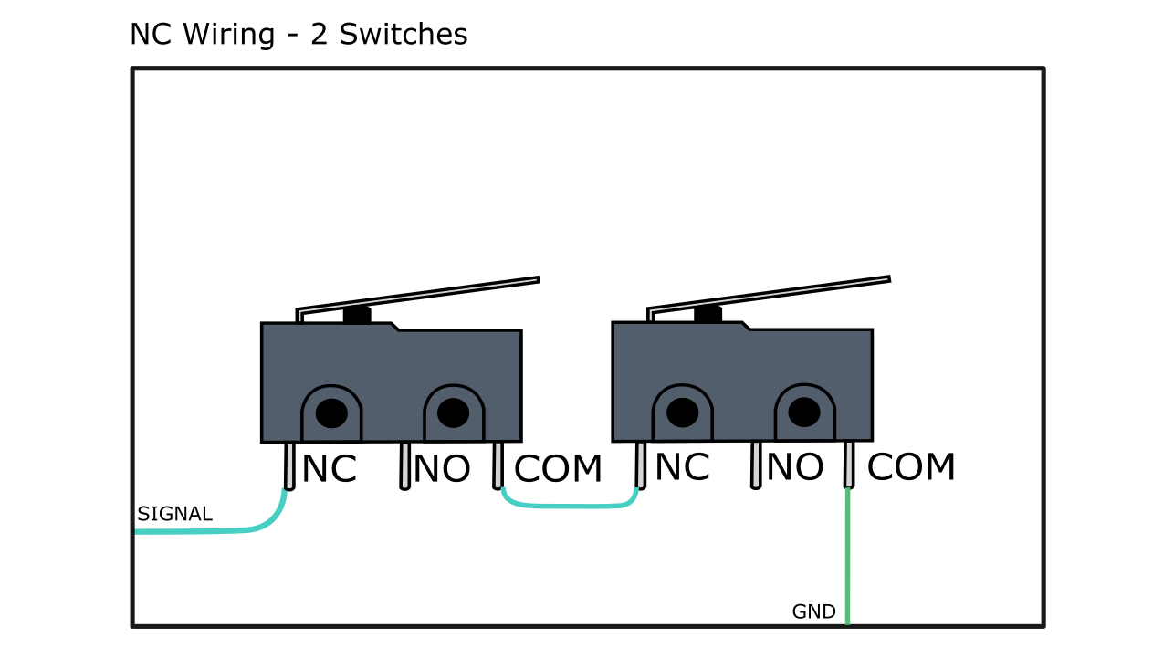
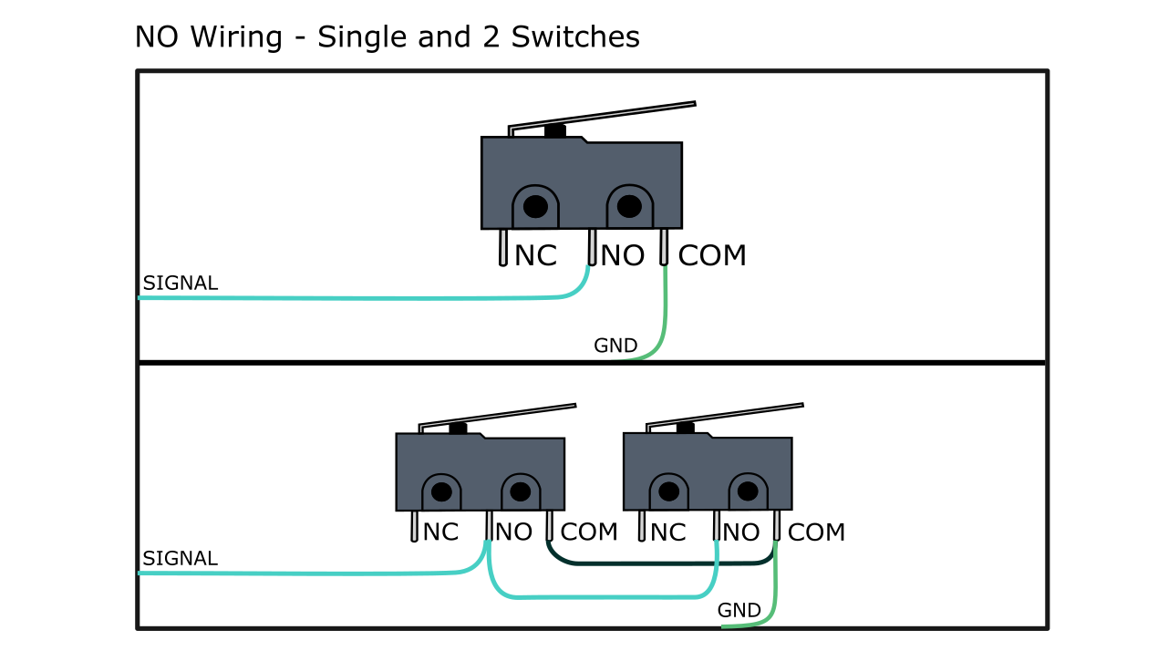
The type of switch used must be considered for proper wiring. For NO and NC mechanical switches, refer to the diagrams below for proper wiring. The blue lines indicate the signal line (XLim, YLim and ZLim) and the green lines indicate the ground line (GND). If you are using two switches per axis, the wiring between the them is indicated below as well.
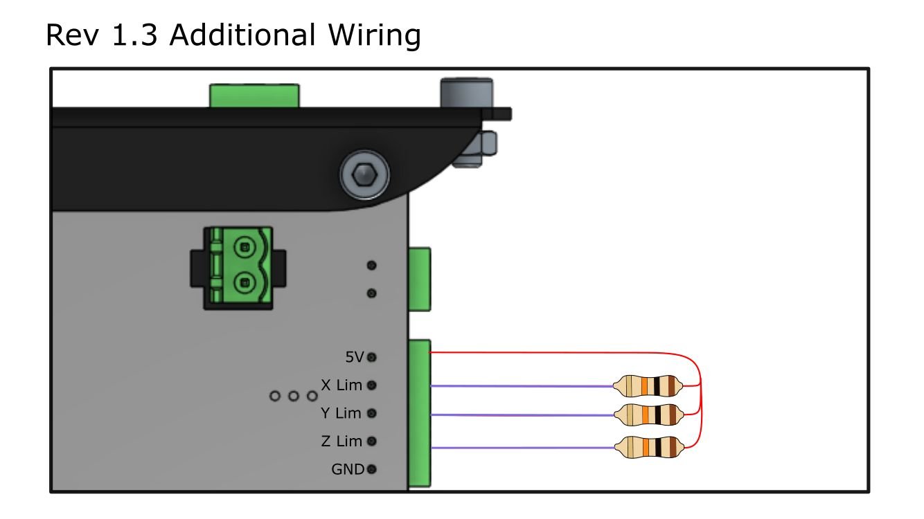
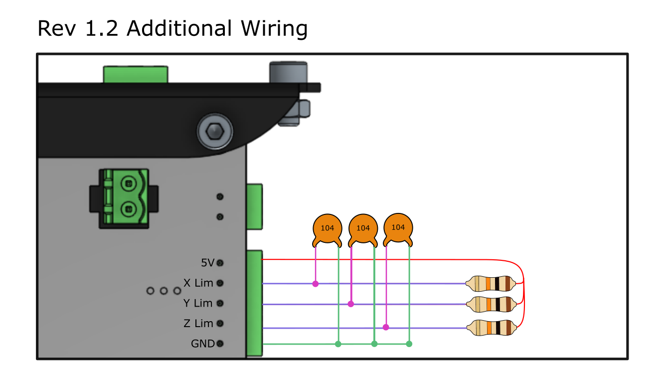
If you have a Rev 1.2 or 1.3 LongBoard, it is necessary to attach the resistors and/or capacitors as specified. Refer to the diagrams below for the additional wiring. The red 5V line is used to produce the noise filtering effects via capacitor and to establish the correct voltage via resistor.
The limit switches must also be included as described in the previous diagrams, making connections between their respective signal line and ground. In Rev 1.2, you wire the limit switch between the resistor and the capacitor. In Rev 1.3, you wire the limit switch between the resistor and the signal pin.
Before you solder anything, make a plan and dry fit all these components into their approximate locations. Once you have settled on their placements, you can solder your circuit together.
Firmware Settings
Once you’ve assembled all the electrical connections to the LongBoard, you can enable limit switches, in which you will need to change a couple of settings on your LongMill’s firmware. Settings can be changed by sending the command to update the EEPROM settings manually through the console, or using the “Firmware Tool” on gSender. Below, we have listed the settings that you may want to enable.
Current
Don’t forget to hit the Apply Settings button once your changes have been made.
Classic gSender
$5 – Limit pins invert, boolean
For NO or NPN, this setting should be $5=0, so that the input and output pins are set to the proper voltage level to function properly. For NC or PNP, this setting should be set to $5=1.
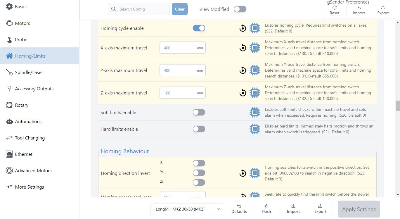
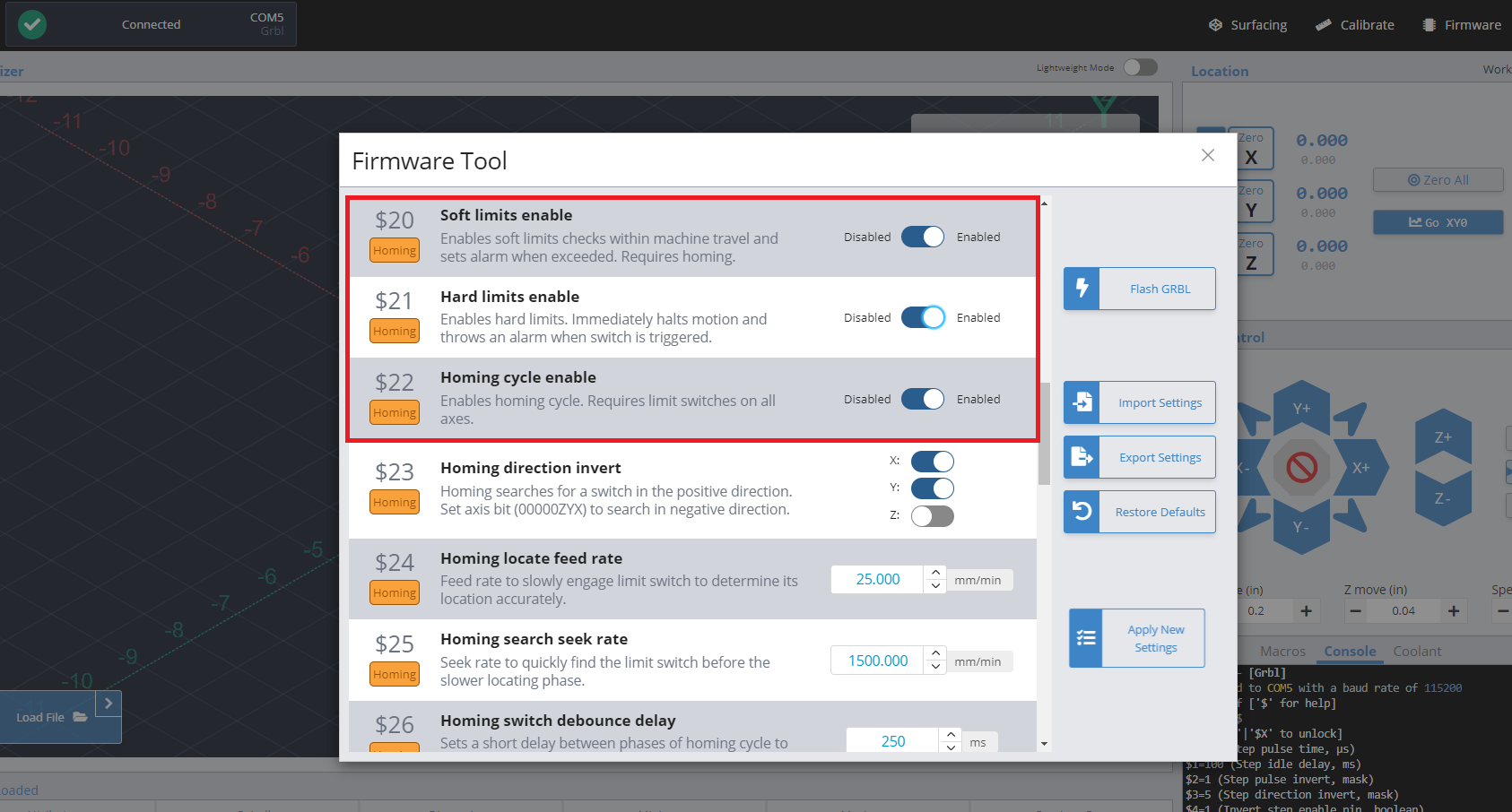
$20 and $21 – Soft limits and hard limits enable
If you have two switches per axis, use $20=0 and $21=1 to enable hard limits. If you have one switch per axis, use $20=1 and $21=0 to enable soft limits.
$22 – Homing cycle, boolean
By default, your LongMill is set to $22=0, disabling the ability to use the homing cycle. Activate homing by sending the command $22=1. When homing is activated, every time your machine is connected, your machine will ask you to home the machine as a safety feature. You can home your machine by sending the command $H through the console, or use the “Home” button on your g-code sender.
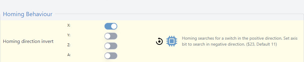
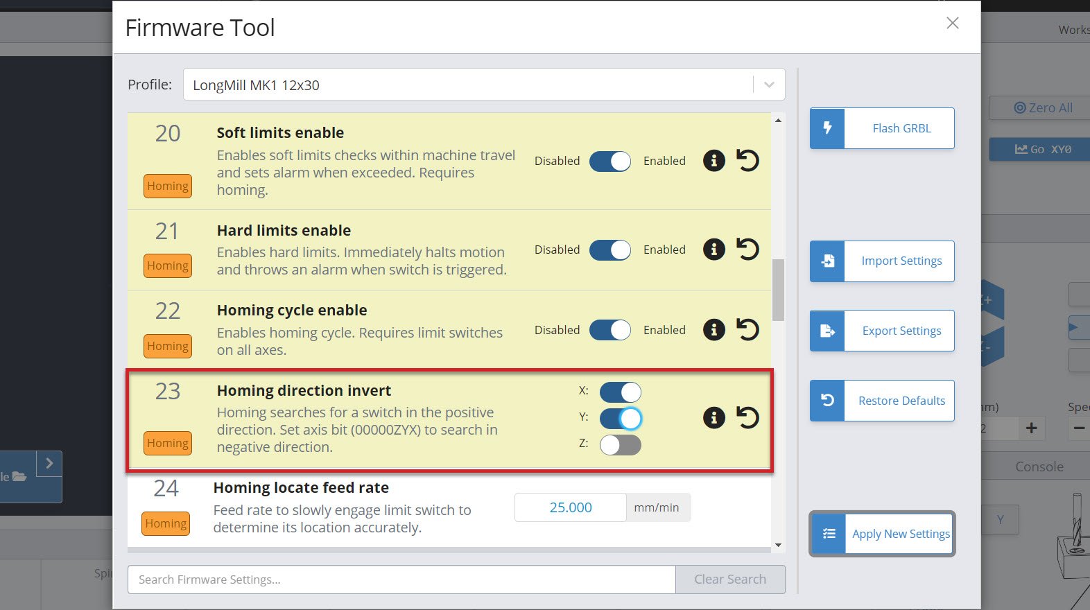
$23 – Homing direction invert, mask
By default, your LongMill is set to $23=0. This setting is used to select the direction that the machine moves to home each axis. By default, when $23=0, the machine will move home up in the Z direction, and then to the upper left corner (moving towards the left on the X-axis and moving up to the top on the Y-axis).
In some cases you may want to change the direction that you want to home, either based on the location of your limit switch and the way you want to set up your workflow. For example, if you have a square at the bottom left corner of your machine where you can set a corner you can set rectangular material on so that you can repeat the same job over and over again, you may want to invert the Y-axis homing direction so that your machine homes to the bottom left corner of the machine.
| Setting Value | Mask | Invert X | Invert Y | Invert Z |
|---|---|---|---|---|
| 0 | 00000000 | N | N | N |
| 1 | 00000001 | Y | N | N |
| 2 | 00000010 | N | Y | N |
| 3 | 00000011 | Y | Y | N |
| 4 | 00000100 | N | N | Y |
| 5 | 00000101 | Y | N | Y |
| 6 | 00000110 | N | Y | Y |
| 7 | 00000111 | Y | Y | Y |
When looking at the table on inverting each axis, setting value 3 inverts the direction of the X and Y homing directions. So by sending command $23=3, the X-axis and Y-axis homing directions will be reversed and the machine will home in the bottom left corner.
In gSender, you can use the toggles instead to change the direction of each axis.
$24 – Homing locate feed rate, mm/min
By default, this speed is set to $24=25, which sets the homing locate feed rate to 25mm/min. When homing your machine, the machine will first move at a preset speed (see $25 – Homing Seek) to more rapidly reach the limit switch, move away from the switch to deactivate it, then move towards the limit switch at a slower speed for a more accurate reading.
We recommend keeping this value at 25mm/min as it works for most limit switches.
$25 – Homing seek, mm/min
By default, this speed is set to $25=1500, which sets the homing search seek rate to 500mm/min. This is the speed of which the machine will move to locate each limit switch.
$26 Homing switch debounce delay, ms
By default, this time is set to $26=250, which controls the delay before the controller measuring if the signal is on or off. Some switches can take a few moments before a on or off signal is defined. We recommend keeping this at its default setting. However, if you find that your switch randomly triggers for no reason, you may want to increase the debounce delay.
$27 Homing pull-off distance, mm
By default, this distance is set to $27=1. This distance determines the distance that the machine needs to move away from the switch to un-trigger it. For some sensors, such as mechanical switches, this can be a few millimeters, while inductive proximity sensors may only need a fraction of a millimeter. For inductive sensors, we recommend keeping your default homing pull-off distance at 1mm, while if you are using mechanical switches, use about 2-4mm to ensure that your switch is completely un-triggered after your homing sequence.