
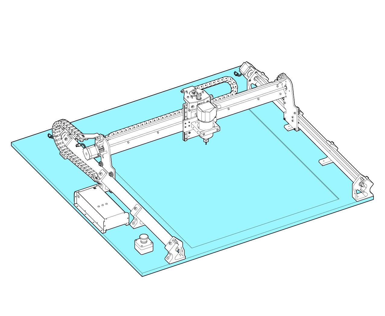
The LongMill is designed to be mounted to a flat surface which is provided by the user. This could be as simple as a single sheet of material, or as intricate as a multi-piece torsion table with t-tracks and threaded inserts. One thing is to ensure that you’ve got a flat sheet (or multiple flat sheets) of material within the cutting area of the machine. This “wasteboard” area is where the material you will cut will sit on and serves to be cut into and replaced when needed.
We do not ship LongMills with a wasteboard because:
- It saves the cost for shipping. For example, a 4ftx4ft piece of 3/4″ MDF shipped often costs over a hundred dollars in shipping and is very easy to damage during transit. You can usually find a full 4ftx8ft sheet of 3/4″ MDF for under $60 at your local lumber or hardware store.
- Users can choose the size and material of the wasteboard to match their needs.
Suitable wasteboard materials
The easiest setup that we recommend is a flat, clean piece of 3/4″ MDF to act as your mounting surface and your wasteboard. This is because 3/4″ MDF is quite stiff and is readily accessible in 4’x4′ and 2’x2′ sizes from most big- box hardware stores or a lumber store. Any similar piece of thick, flat material would also suffice; you can choose at your own discretion. If you’re looking for more of a flashy setup, you can check out some of our community members’ table/wasteboard builds for inspiration.
Machine Dimensions
When getting ready to mount your LongMill, the most important dimensions you’ll need to know are the size of its foot base and the total outline of the machine. As long as your mounting surface is at least the size of the foot base and you’ve left enough space around your mounting surface to account for the total machine outline, then your setup will be suitable.
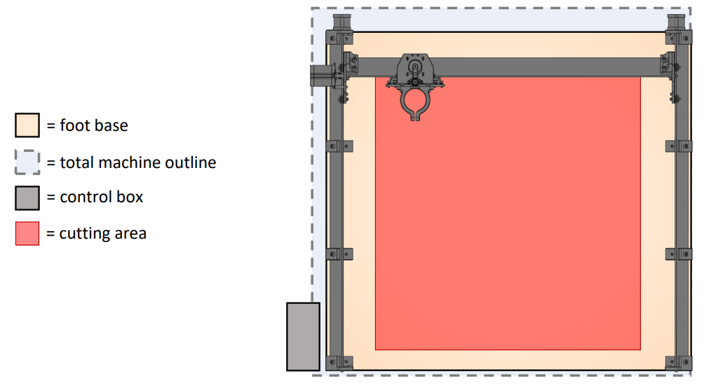
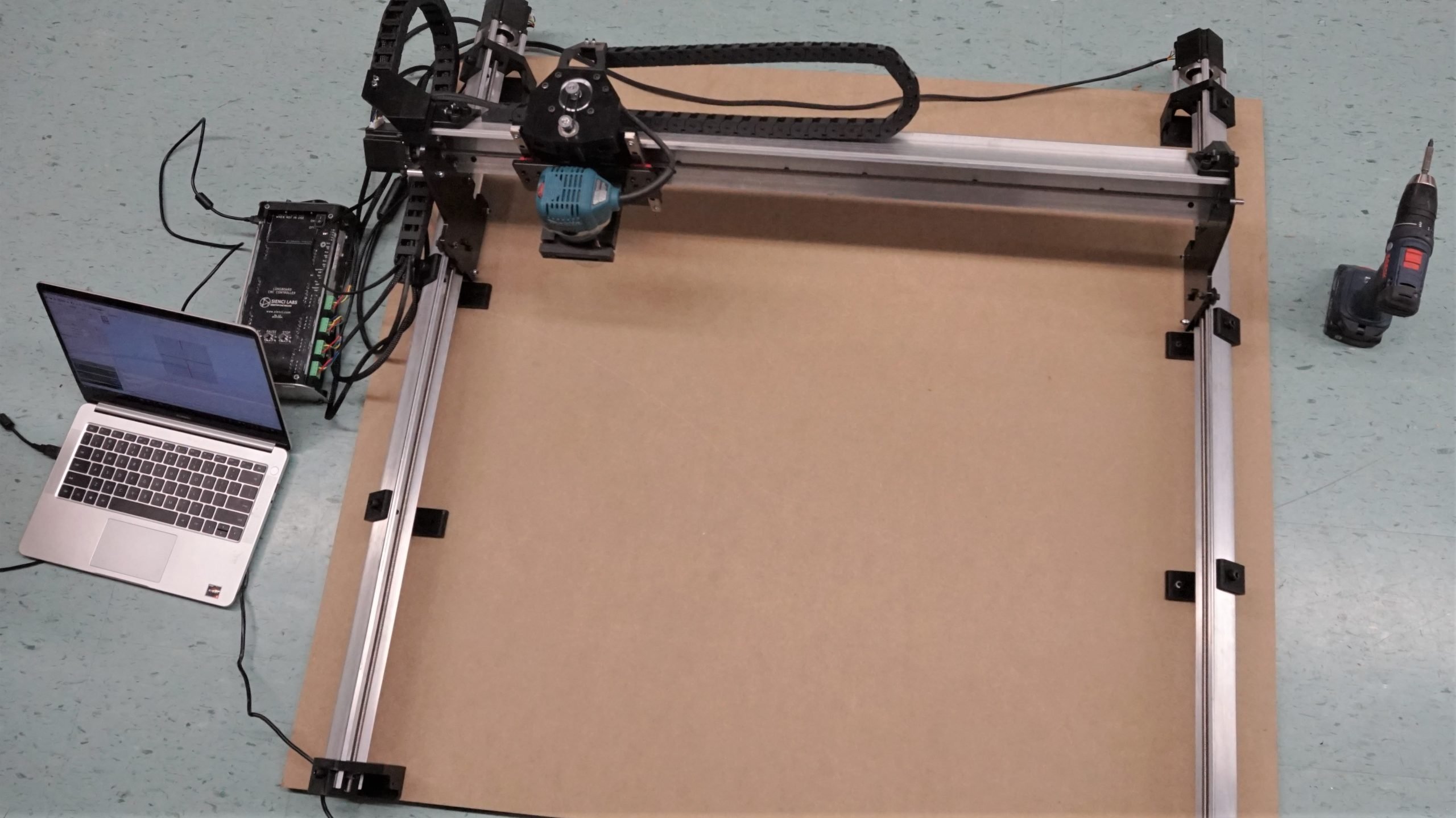
The control box is also something you should plan for, as the design of the machine favours placing the control box on the left side of the machine whether it’s sitting on the table or mounted to the side or underside of the surface. The control box has buttons on the top which can Play, Pause, and Stop the machine’s motion so it’s a good idea to keep it mounted near your CNC. It also has a USB input on the left side, motor and other outputs on the right side, and the power input on the back side, so make sure to keep some space around it for cable management.

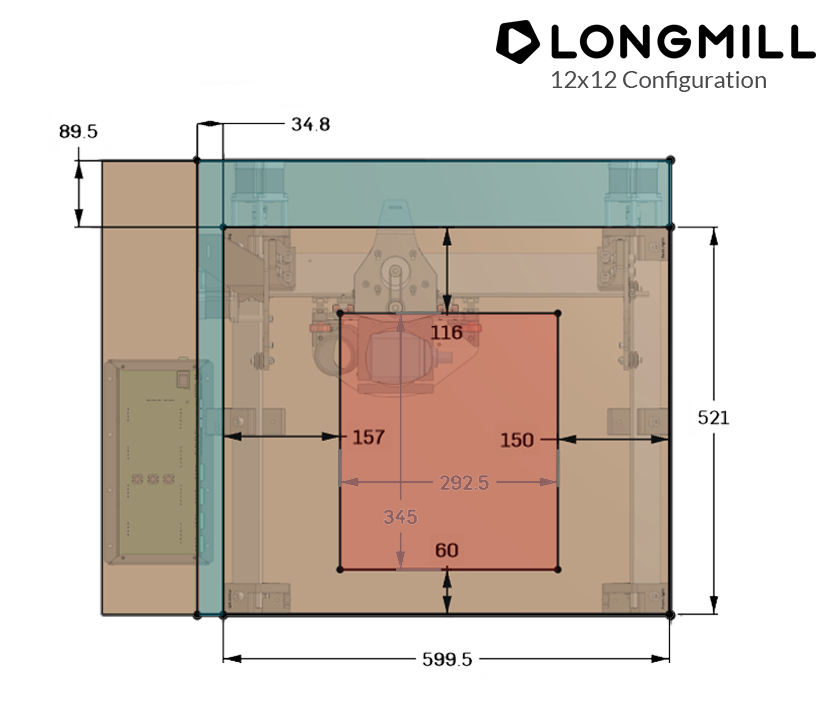
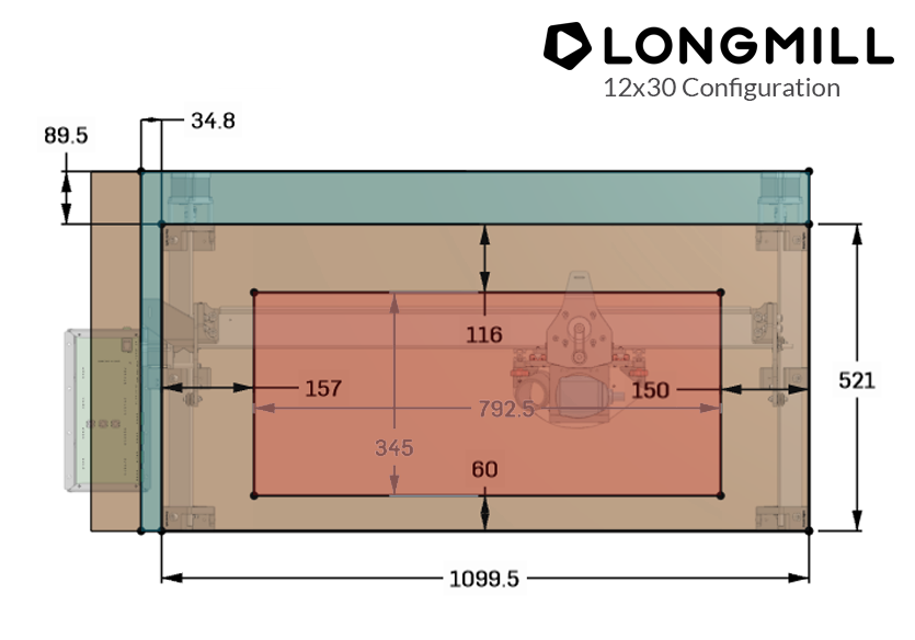
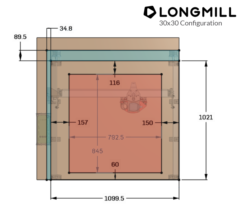
Once assembled, each model of the LongMill (12×12, 12×30, and 30×30) is designed to generally fit on a 2×2′, 2×4′, and 4×4′ surface respectively. The diagrams below show a more detailed view for each model:
- The red area inside the main box shows the cutting area as an offset from the foot base. It’s based off the center-point of the router, thus you can plane an area larger than what’s stated if you’re using a large surfacing bit.
- The blue area outside the main box shows the hanging parts as an offset from the foot base which makes up the total machine outline.
- If you have the dust shoe attachment in place, it’ll reduce your cutting travel in the X-dimension by approximately 34mm.
- These diagrams have got a small buffer on the cutting area (i.e. it’s been shrunken slightly) since each part has its own manufacturing tolerance and can come together differently in assembly so we want to ensure we’re providing a reasonable guarantee on what can be expected from your machine.
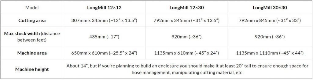
At the end of the day, this leaves you with:
Mounting your LongMill
To ensure that your machine is mounted securely and accurately, we’ve created a series of steps to help you do so. We highly recommend following these steps exactly, as the order of these steps matter. You’ll need a computer to be connected to the machine in order to align it properly.
We will start by checking the tension of the Delrin v-wheels. As we did in the previous steps, we want to make sure that the wheels barely turn with our fingers by adjusting the eccentric nuts.
We will also properly tension the Delrin anti-backlash nuts. Turn the tensioning screw a little bit at a time. Check for play by moving the gantry back and forth and seeing if there is any excess movement. Do not over tighten, usually a half turn is more than enough.
Gently put your LongMill on the mounting surface and shuffle it over roughly where you want it. In this case we’re using a 4’x4′ MDF sheet as a combination mounting surface and wasteboard which we had cut to 42 inches to better fit in a car. We’ll be mounting it in the middle and have the electronics box sit off the material to the side.

Once positioned, start by moving the machine all the way to the rearmost position by jogging in the y-axis on your control software. Keep moving backwards until you hear a grinding coming from the motors on both sides; this is to confirm that your machine is all the way back and it aligns the left-side feet to the right-side feet.

We’ll start by mounting the right side of the machine. Using a drill with a long Robertson driver or a short one on a bit extender works best for driving in the screws so that you have the necessary reach. You can use the particle board screws provided, or use your own mounting hardware depending on your material or its thickness, but please ensure that you don’t use counter-sunk wood screws to attach the feet as this will crack them.
The screws included are 1-1/4″, 1-1/2″, and 2″ size #8 particle board screws. Each foot has two holes for mounting where the shortest screws are meant for the inside and the longer one are for the outside. Please note that the 2″ screws WILL go through 3/4″ MDF, but were still included since they can hold the LongMill feet down better. If you choose to use them, make sure that the surface under the board will not be damaged if you have screws coming out the bottom.
Alright, begin by moving the machine a couple of inches forward and mount using the inside holes of the top and bottom feet using two wood screws (1-1/4″).
Next, we’ll put screws in the other two spots on the same side, this time on the middle feet.
Now fasten the diagonal mounting points of all the right-side feet using the longer screws. If you’d like to pre-drill the diagonal holes it’ll snug the feet up even better against the board face when the wood screws are installed.
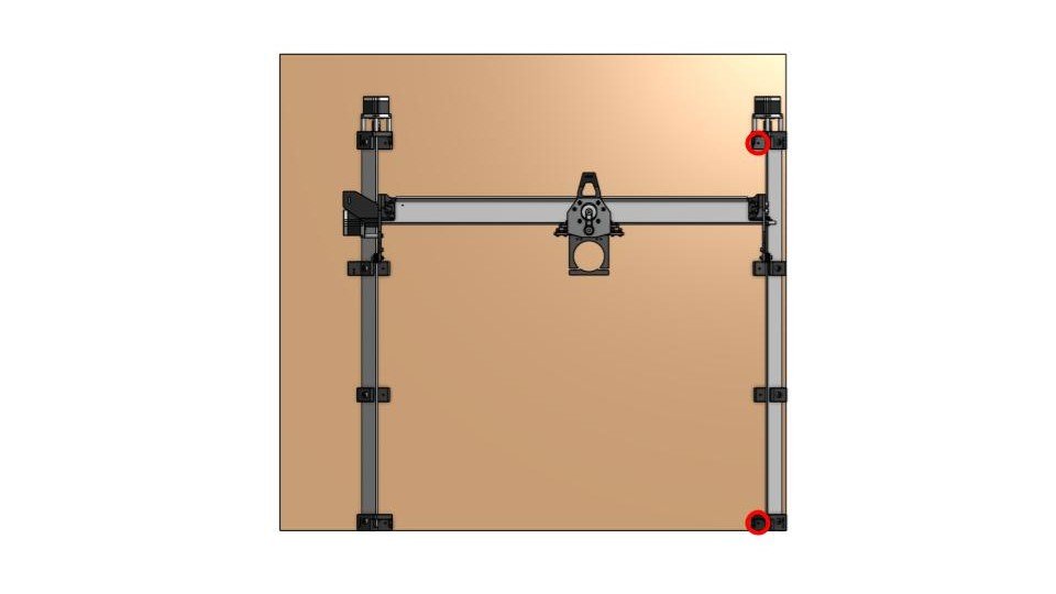
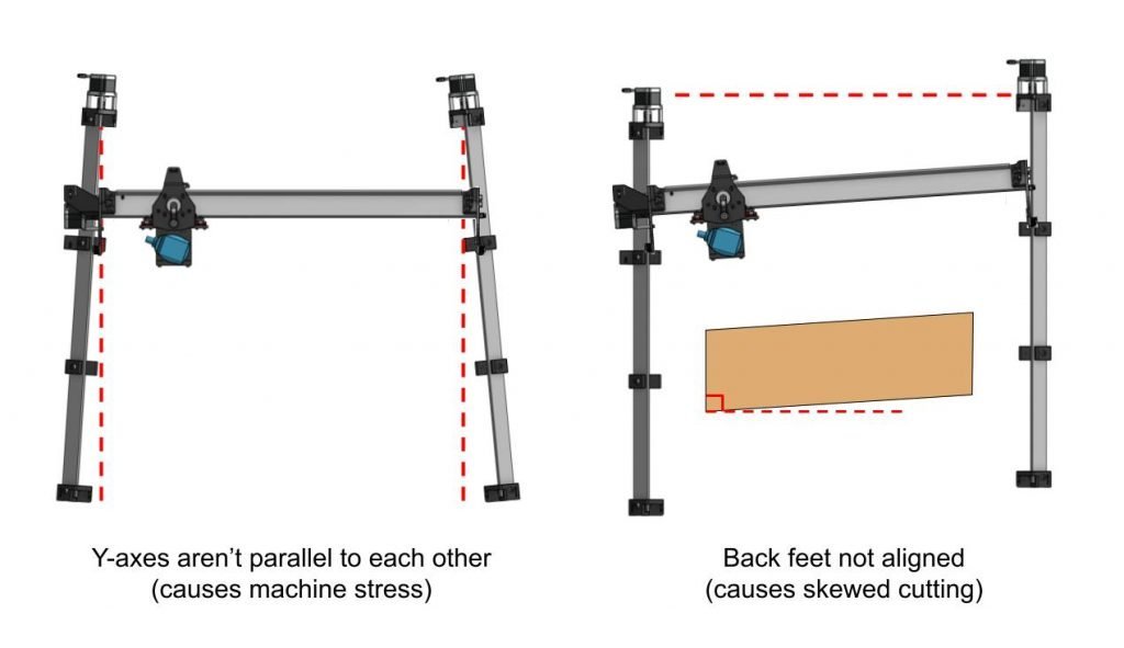
At this point the right side of your machine will be fully secure. When mounting the left side, we’ll want to ensure it’s mounted parallel to the right side and also that the back feet are aligned to each other. You can see in the diagram below why mounting the rails both parallel and in-line is important to ensure the CNC isn’t overly stressed and also cuts how you’d expect it to.
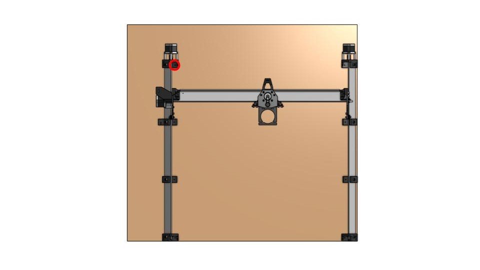
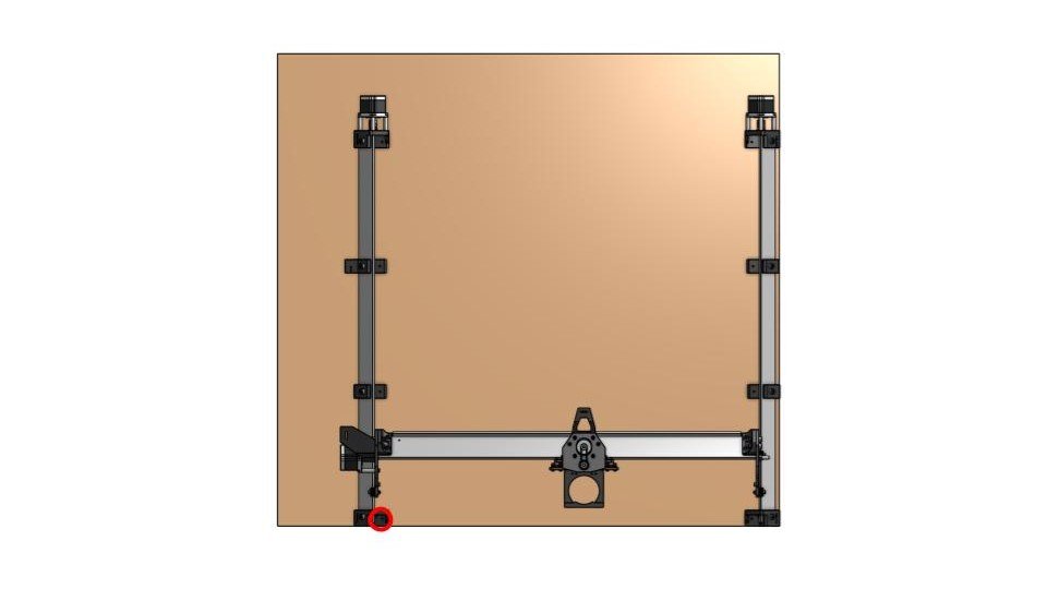
To combat this misalignment, first you’ll want to start with the back, left foot on its inside hole (circled). Before attaching this screw, the X-axis should be moved nearly to the back. In addition, if you have some sort of straight edge on hand (level, carpenters square, etc.) you can even butt the table up against a wall and space off the wall if need be – ultimately the goal is to align the two back feet of the LongMill as best as you can. Once you feel confident in the foot placement, drive this first screw into place.
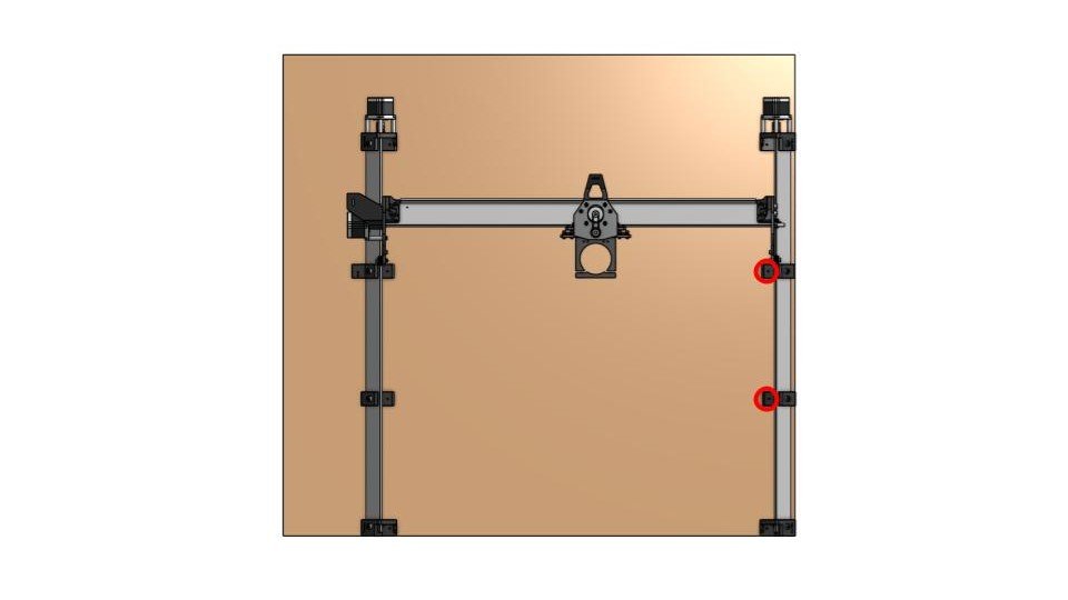
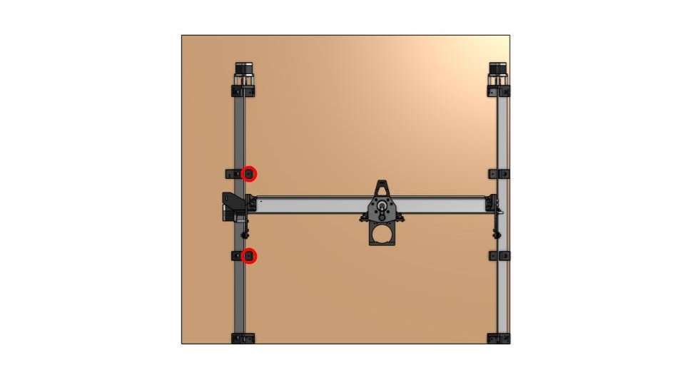
To complete parallel alignment, you’ll be moving the machine towards the front so that it’s right next to the foot you want to secure next. With the back foot done in the last step, move the machine down so that it is roughly in the middle of it’s length, then secure the insides of the next two feet:
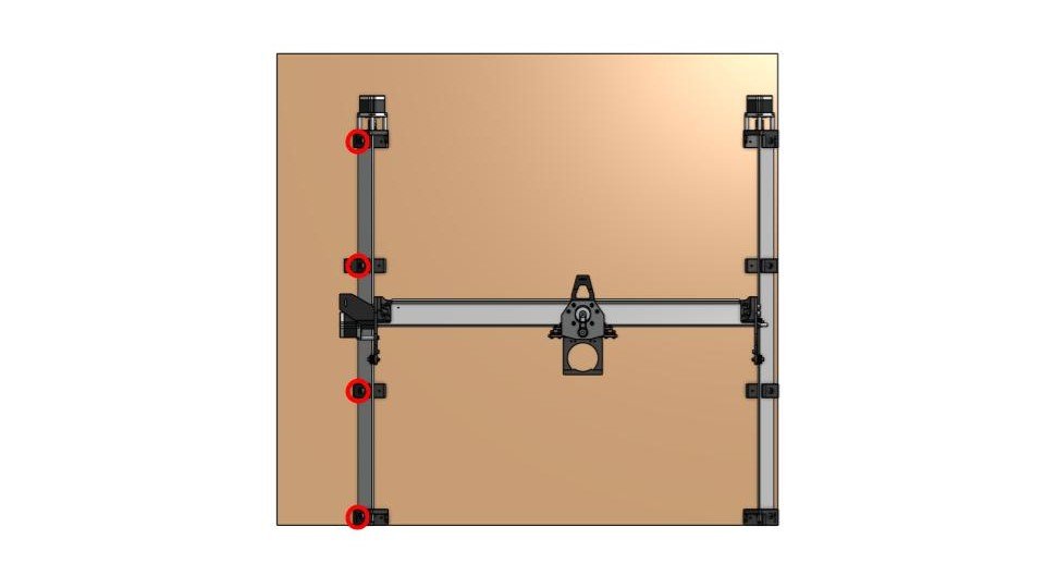
Finally, move it to the front and secure the inside of the front left foot:
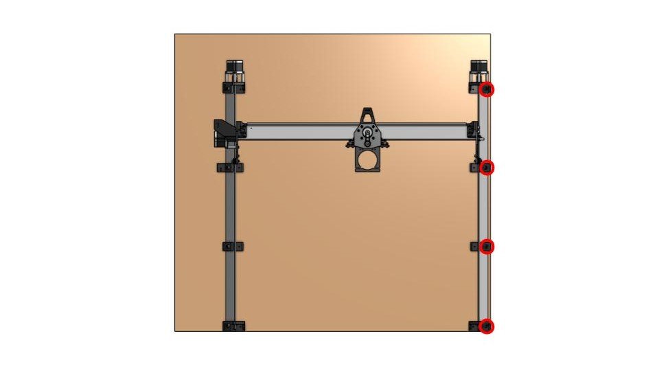
Now move the machine again to the middle spot and use the longer screws to finish mounting the feet using their diagonal mounting holes.
Your machine should now be fully secure and square to its mounting surface. An easy squareness check is to tape a pencil or marker to your router mount and draw a large L or box shape manually by using the X and Y movements on your computer. You’ll be able to use this in combination with a carpenters square or measuring a 3-4-5 triangle to confirm that your machine has been aligned properly.
From this point, you should be ready to get cutting your first jobs! If you’ve got the touch plate, dust shoe, or t-track add-ons alongside your machine, you’ll see the guide on how to utilize these and put them together after the “Starter Projects” page.
The rest of this Assembly section also contains information on how to surface your wasteboard, ways to get started making more projects, machine maintenance, and a page on troubleshooting in case you happened upon any issues during assembly or during the Starter Projects.