Preparing the X-axis rail
12x12
The 12×12 LongMill is a smaller build envelope so it doesn’t require an X-axis reinforcement bar. Move onto the next step “Attaching the Shoulder Brackets”, but keep in mind that the remaining pictures may show another piece of angled aluminum attached to the back of the X-axis rail. Pay no mind to this since the assembly process is otherwise the same.
12x30 and 30x30
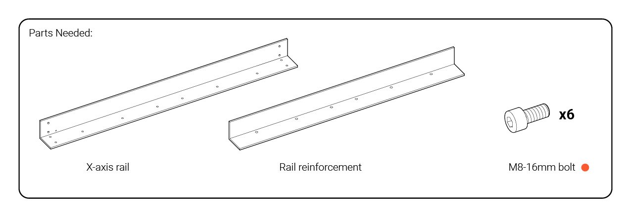
The 12×30 and 30×30 model LongMills use a second aluminum extrusion as a reinforcement bar to make the primary rail on the X-axis more rigid. These are the two longest and largest aluminum lengths on your machine and can be found in the heaviest long box alongside the other rails.
Of the two, the longer one is the X-axis rail and the shorter one is the reinforcement. You can also distinguish the two since the X-axis rail has sets of four threaded holes at its ends.
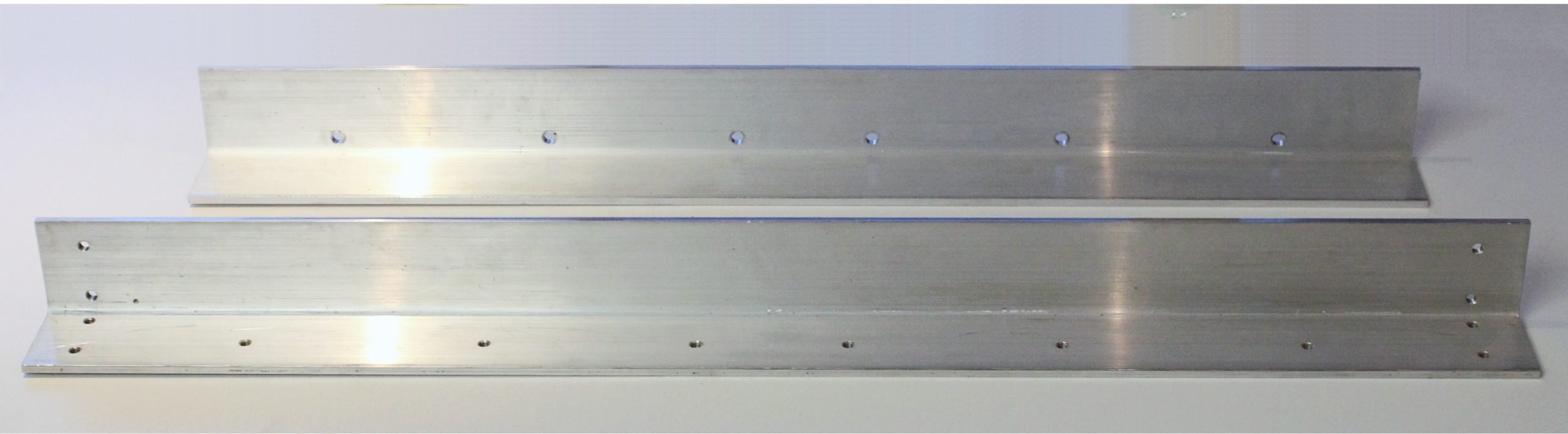
Start by orienting the rails into a ‘lighting bolt’ pattern like in the photo so that the set of six holes on both can be aligned. Also, make sure to check that the small threaded hole on the X-axis rail (yellow) is oriented as shown so that you’ll be able to attach your drag chain later on.
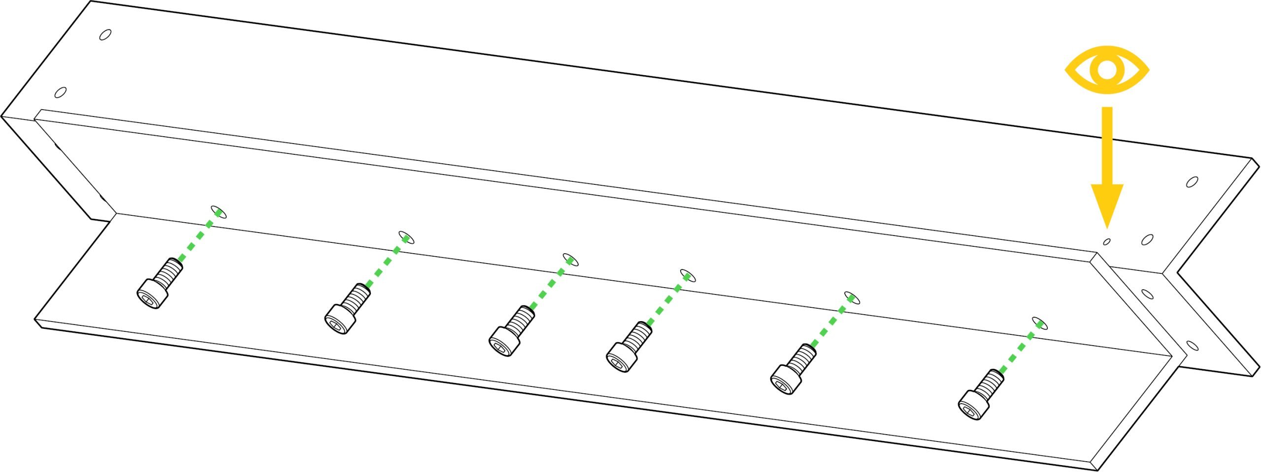
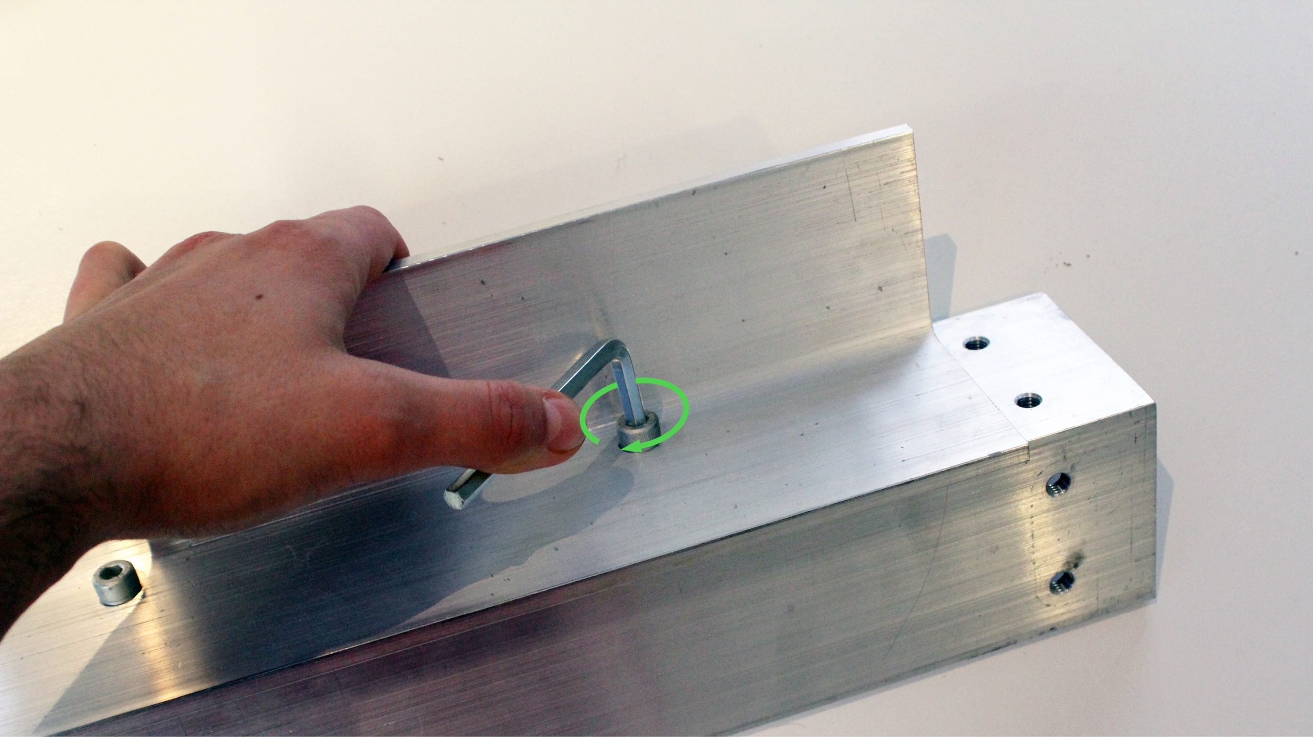
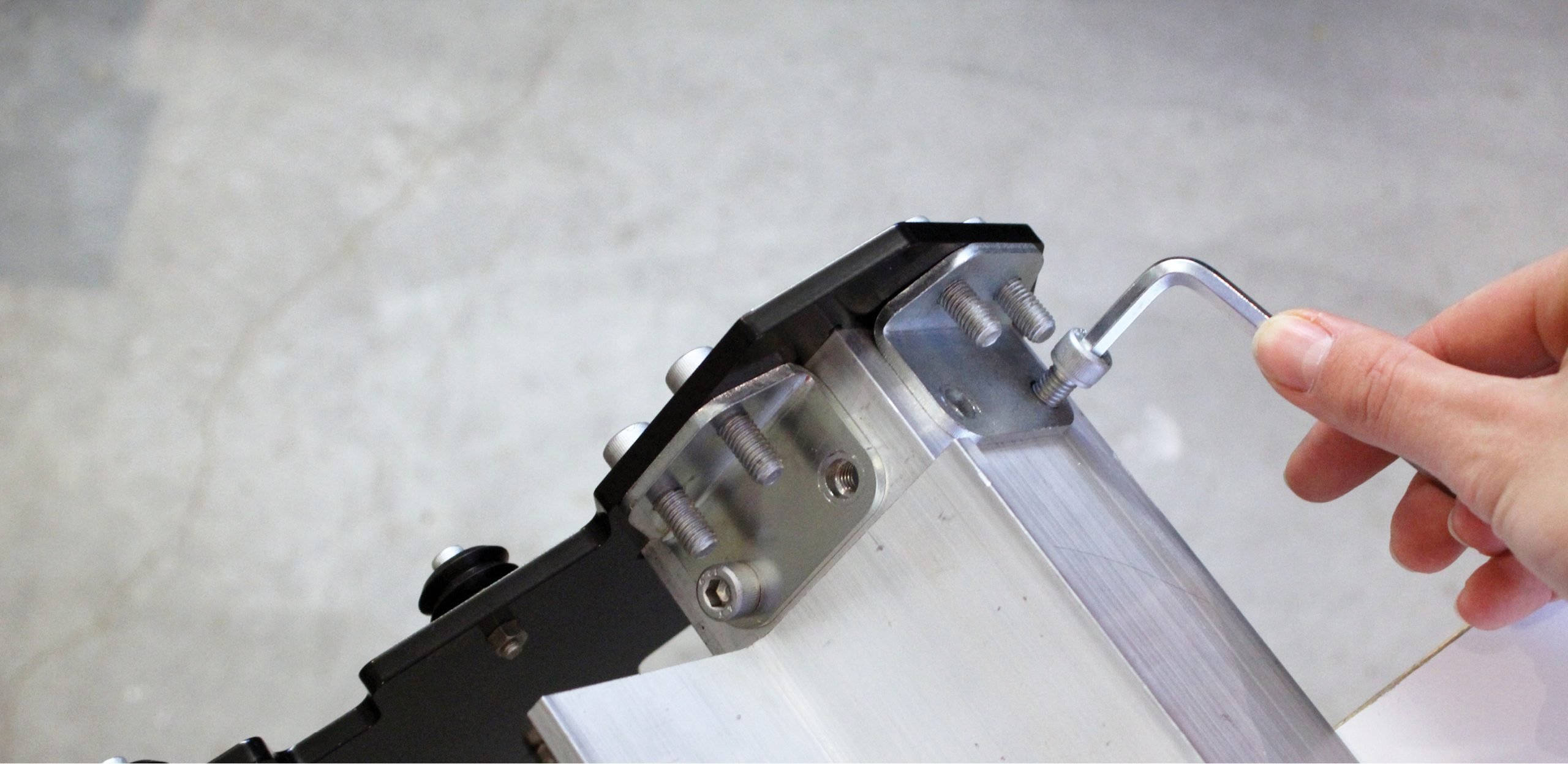
Grabbing the M8-16mm bolts from the orange bag, you can use six of these to fasten these parts together; the bolts will go through the larger holes on the reinforcement bar and thread into the X-axis rail from the back (pictured). Start by turning each of these short M8 bolts in by hand to get all the holes aligned, then go back and tighten each of them down well with a size 6 Allen key.
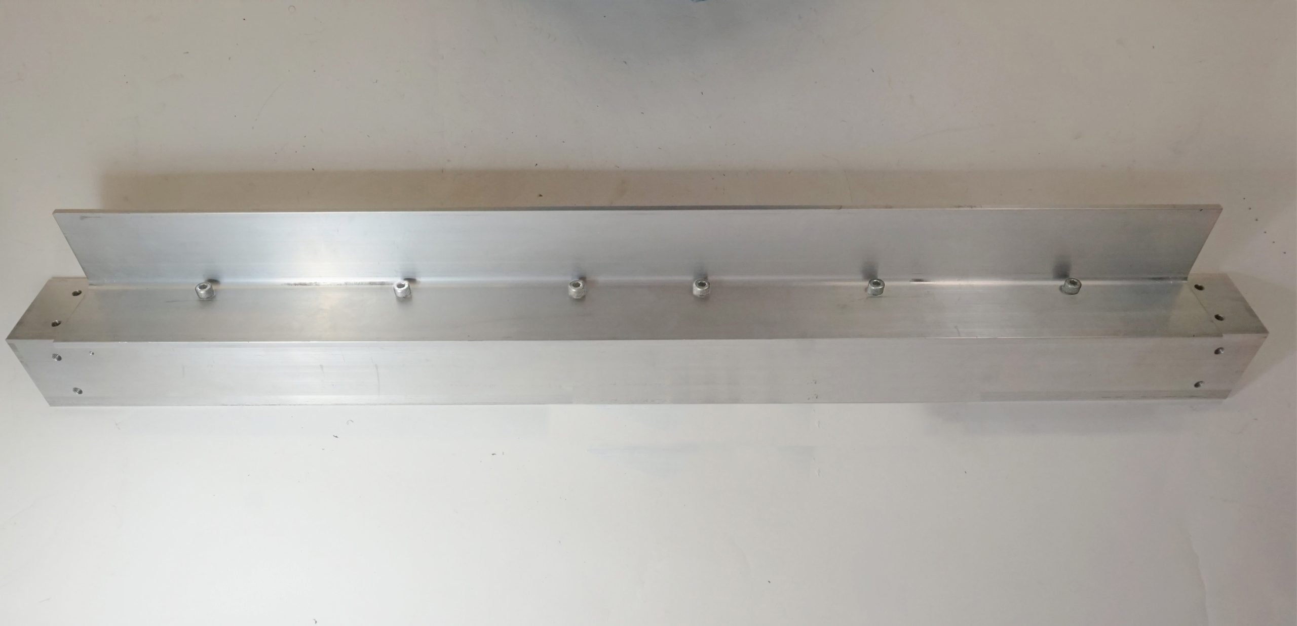
Your completed rail should now look something like this.
Sandwiching the rail with the Y-gantries
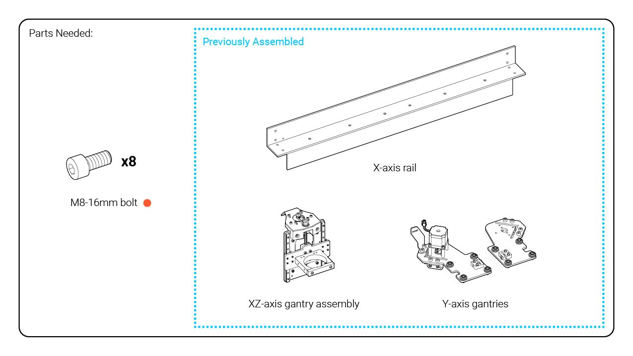
After the previous step, you should now have four major assemblies completed: the XZ-axis gantry, the two Y-gantries, and the X-axis rail. These assemblies will all be coming together in this step, starting by sliding the XZ-axis gantry assembly onto the X-axis rail.
DO NOT stand the completed assembly up on the v-wheels, it can roll away or become unbalanced which may cause it to fall and become damaged; just leave it laying on its back for the next steps. You can consider propping it up at an angle as well if you don’t want the weight of the assembly pressing on the back of the Z-axis motor mount.
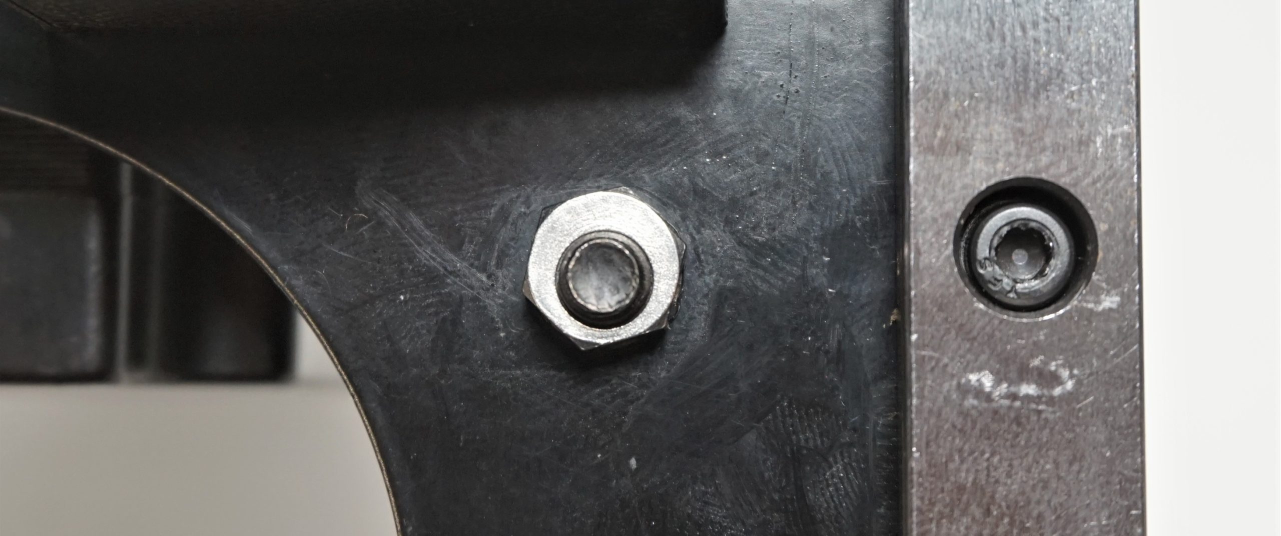
Before we start, you want to make sure that the eccentric nuts on the XZ-gantry are positioned correctly; this can be checked visually. Since the eccentric nuts have an offset hole point, rotating the nut will change the hole position. Looking at the gantry assembly from the front, this pictures shows the top, right eccentric nut at its lowest position. This puts the v-wheel closest to the bottom v-wheel, making the wheel spacing too narrow to install onto the X-axis rail.
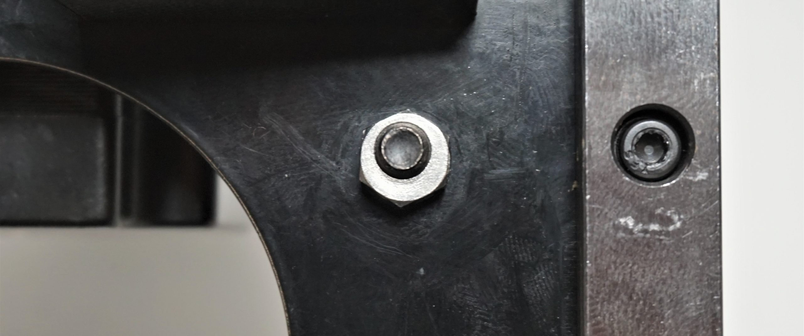
Below, the eccentric nut is in its highest position. This spreads the v-wheels furthest apart, making it easy to slide the gantry on. This is how you want your eccentric nuts to be oriented to proceed with the assembly. This should also demonstrate the concept of how these eccentric nuts can be used to ‘clamp’ the v-wheels onto the aluminum rail in order to have rolling movement along the rail while still being rigid in other directions.
To adjust the eccentric nuts, you’ll have to make sure that the bolts on the v-wheels are still loose, then you’ll be able to use an 8mm wrench or a pair of pliers to rotate the nut into the correct position. Once the eccentric nut is where you want it, re-tighten the bolt with a size 4 Allen key to secure the nut into position. Do this for both nuts.
Lay the X-axis rail down along its length with the inside of the ‘L’ shape facing you and the small, tapped hole oriented to your left. Now take the XZ-axis gantry and slide it onto the rail.

The v-wheels fit over the aluminum rail as pictured below. Check that they are sitting on the rail in the correct fashion and make sure that they roll along the edge of the rail properly.

Now the eccentric nuts need to be tensioned in order for the v-wheels to properly hold onto the X-axis rail. This process is just like before when you widened the eccentric nuts, except now you want to rotate the nuts so that the v-wheels are brought closer together. Follow the process of loosening the v-wheel bolts with an Allen key, rotating the nut a small amount, re- tightening the bolts, and then checking the looseness of the wheels with your fingers. A properly tensioned system should roll smoothly along the rail but it should be difficult to use your fingers to turn the wheels by hand while the gantry is stationary. This applies to all four v-wheels, so be sure to check the wheels on both the top and the bottom.
Next, we’ll be putting the two Y-gantries onto each end of the X-axis rail. The orientation of each Y-gantry will be such that the wheels on the gantry will be facing towards the outside. Let’s start with the right-hand side.
Line up the ‘L’-shaped slot on the steel plate with the rail and tap the plate into place. It works best if you put the slot and the rail head-on so that the slot and the rail line up straight. Note that because of the variance of paint thickness in the slot, you’ll chip some of it out as you mount the plate. These parts are a tight fit so that twisting in the X-axis can be kept to a minimum, so using a mallet and some coercion may be necessary but most importantly take your time.
Once you get the plate on, get the M8-16 bolts from the orange bag and use four of each to secure the steel brackets to the rail. Tighten the bolts down with a size 6 Allen key until snug.
Repeat the same process on the other side, being careful not to cause damage to the motor or the drag chain mount in the process if you need to use some force.
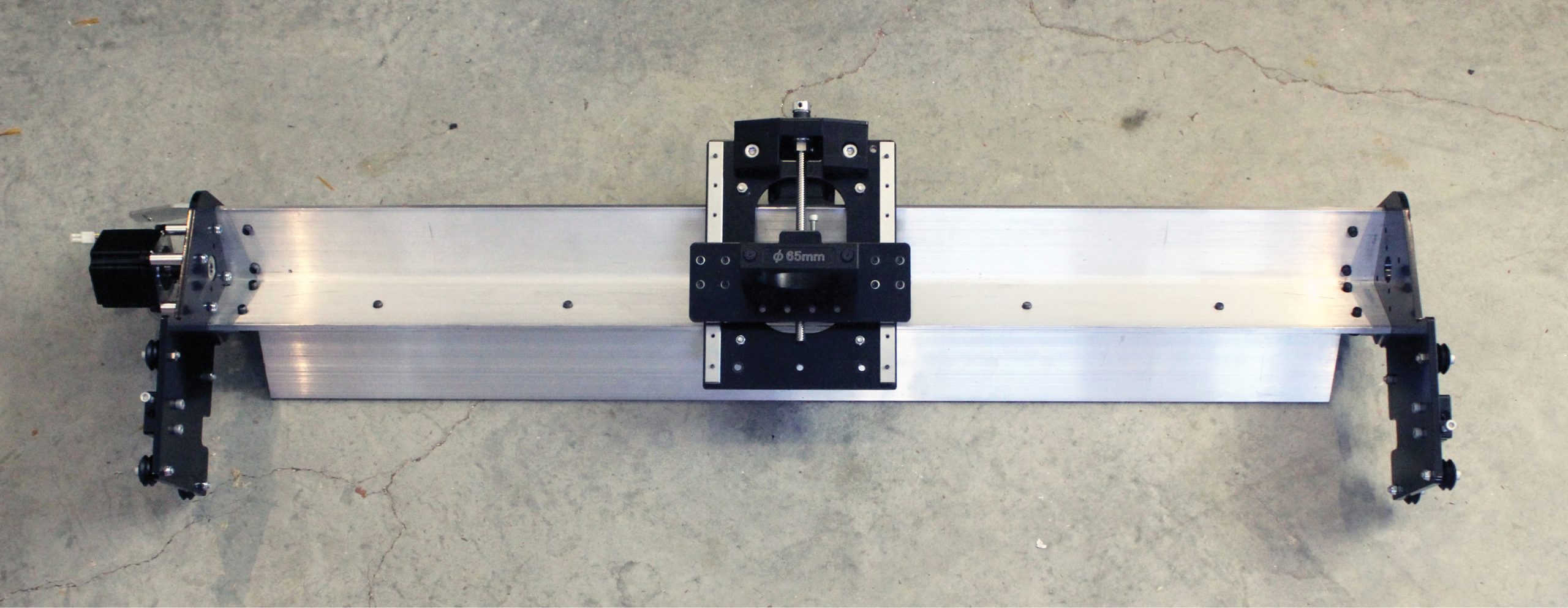
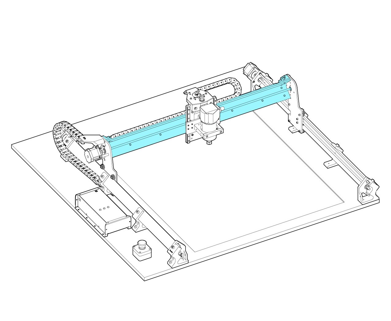
Now that the larger X-axis assembly is done, this is what the completed assembly should look like!
Adding the power transmission components
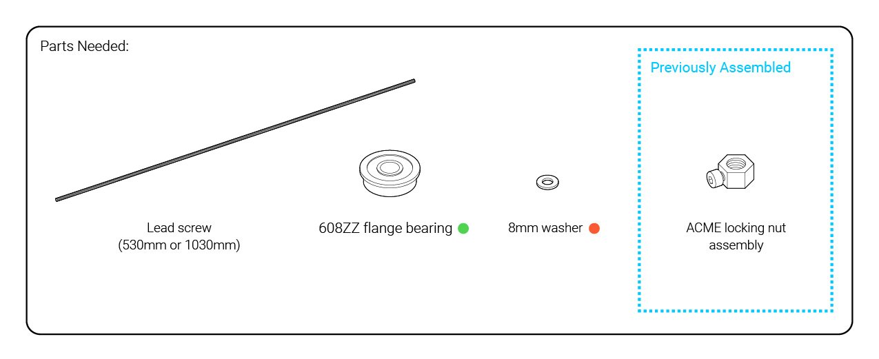
This step will attach the remaining components to the larger X-axis assembly.
Start by grabbing the lead screws which you set aside much earlier in the assembly. Your LongMill comes with three lead screws, not accounting for the earlier one which was used for the Z-axis. For the 12×12 and 30×30 they’re all the same length and for the 12×30 the longer one is for this X-axis assembly. Get your lead screw and run it through the large hole on the right-side Y-gantry, threading it through the plastic block of the anti-backlash assembly as well.


Push the lead screw into the opposite bearing. Don’t push it all the way into the coupler just yet.

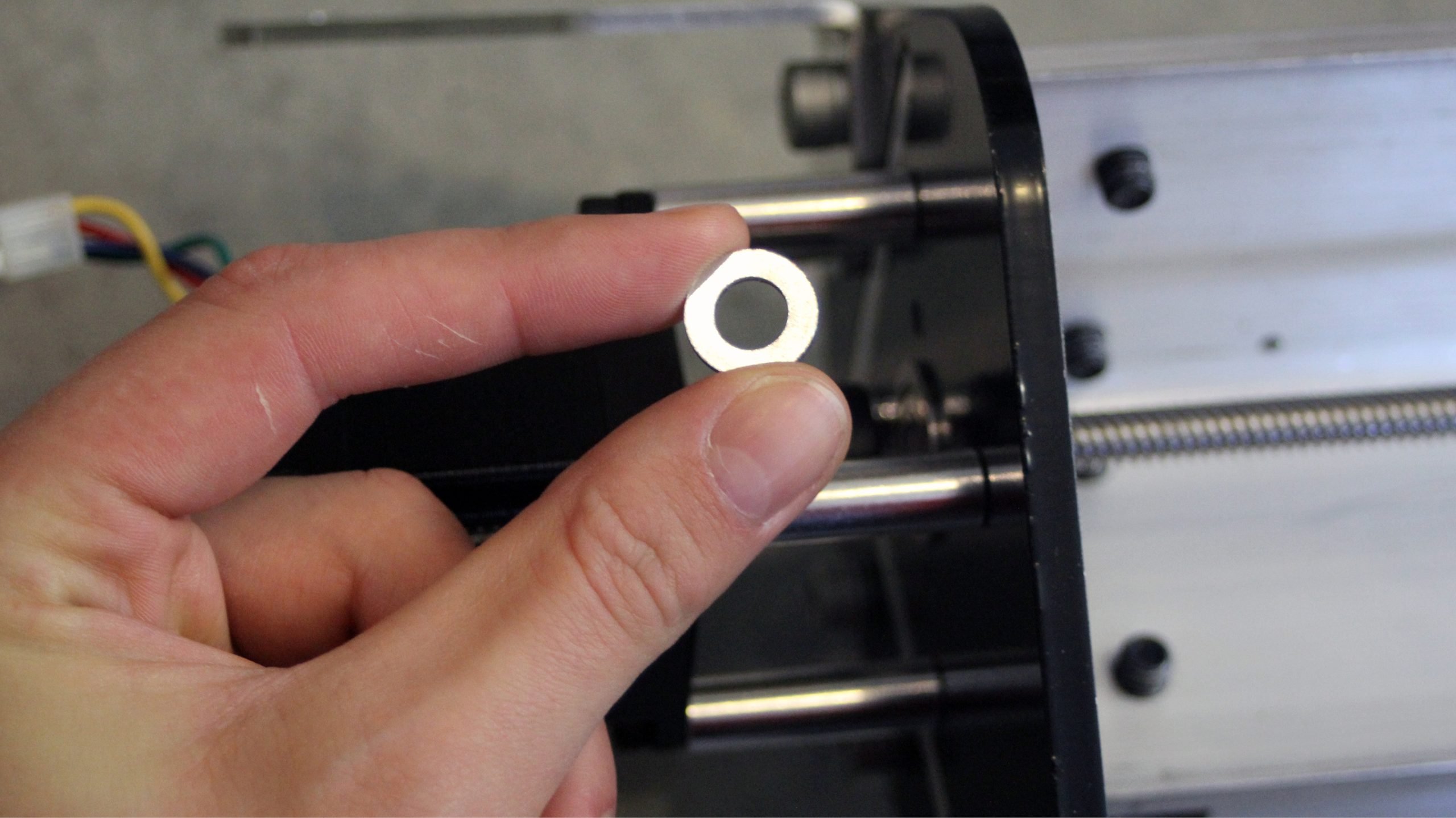
Take an M8 washer (found in the orange bag) and slide it between the coupler and the bearing and then push the lead screw through all three.
If the lead screw is getting a bit stuck on the bearing or coupler, you may have to do some wiggling or lightly tap it into position with a mallet from the other end.

In addition, on the other end you’ll want to push the coupler all the way into the lead screw while holding the lead screw in the other hand so that the coupler is pushes the washer into the face of the flange bearing. Then tighten the set screw – on the lead screw side of the coupler – using a size 2.5 Allen key.

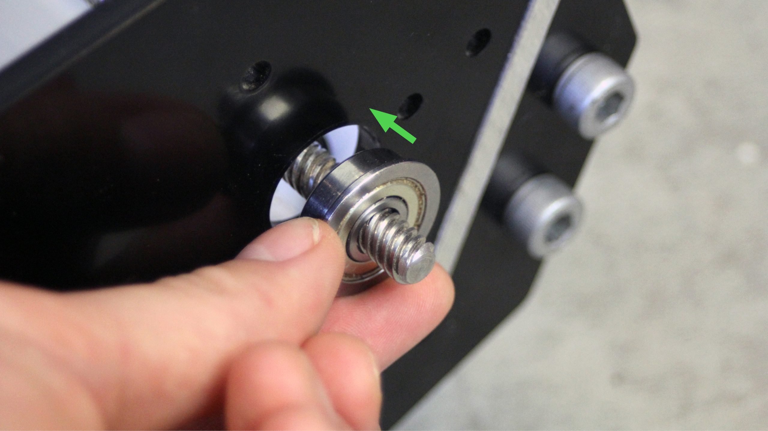
Now on the other side of the X-axis rail assembly, take a second flange bearing and slide it into place as shown. It should fit into the bore on the right-hand side of the right-side steel plate and if the fit is a bit tight then you can wiggle it or tap it into place.
There should still be three ACME locking nut assemblies that you’ve previously assembled. Grab one of these and thread it onto the lead screw from the right, turning it all the way until it’s against the bearing, then tighten the set screw to hold it in place. Make sure the nut is really tightened into place before tightening its set screw.
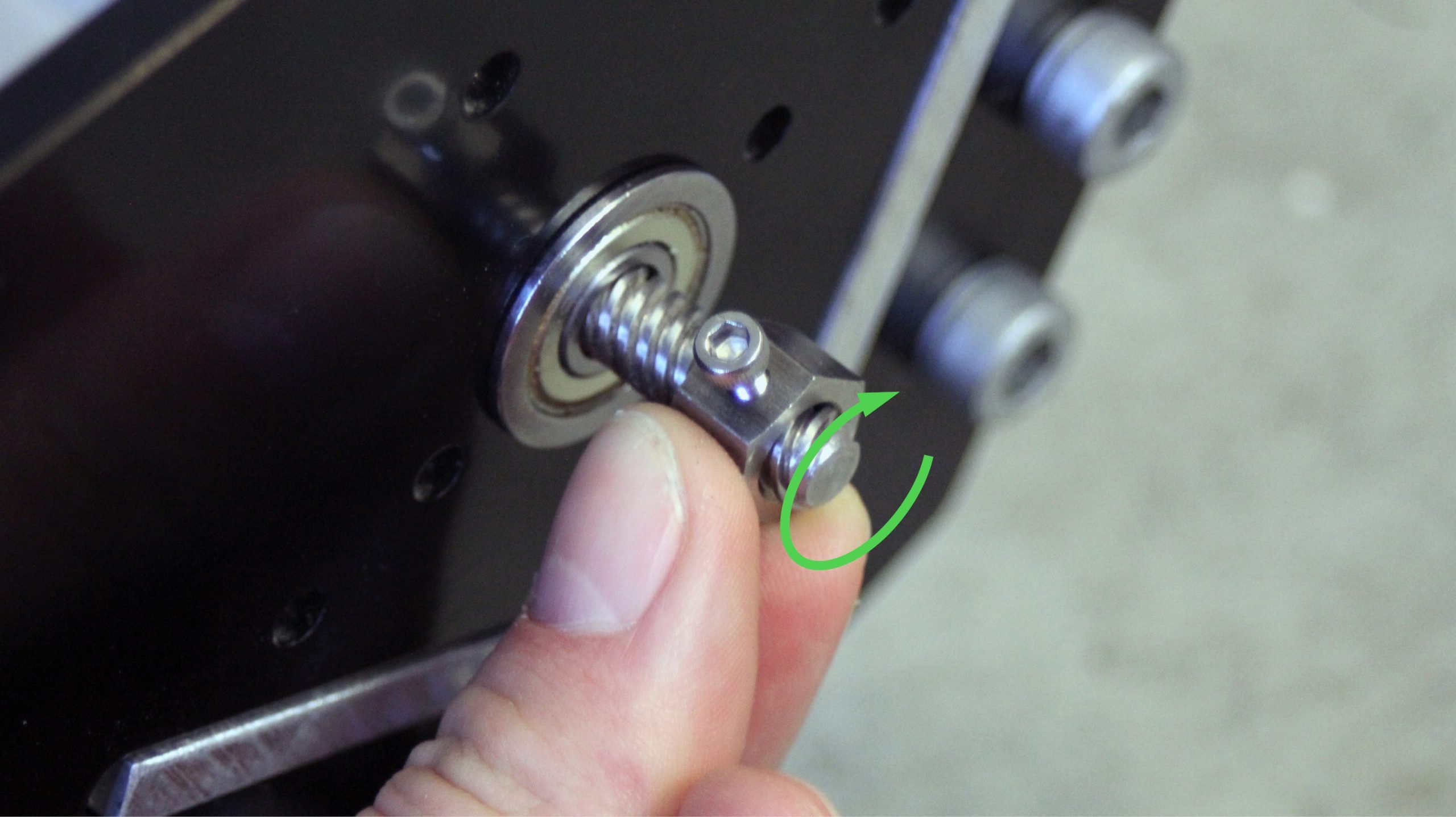
This nut is used in combination with the coupler at the other end of the assembly to constrain the lead screw on the X-axis from moving side-to-side. As such, it’s a good idea to check that everything is secure by gently pulling on the lead screw to check for any looseness. Adjust the couplers and tighten the ACME lock nut more if you feel any play since you should be able to rotate the lead screw freely but not feel any side-to-side looseness.

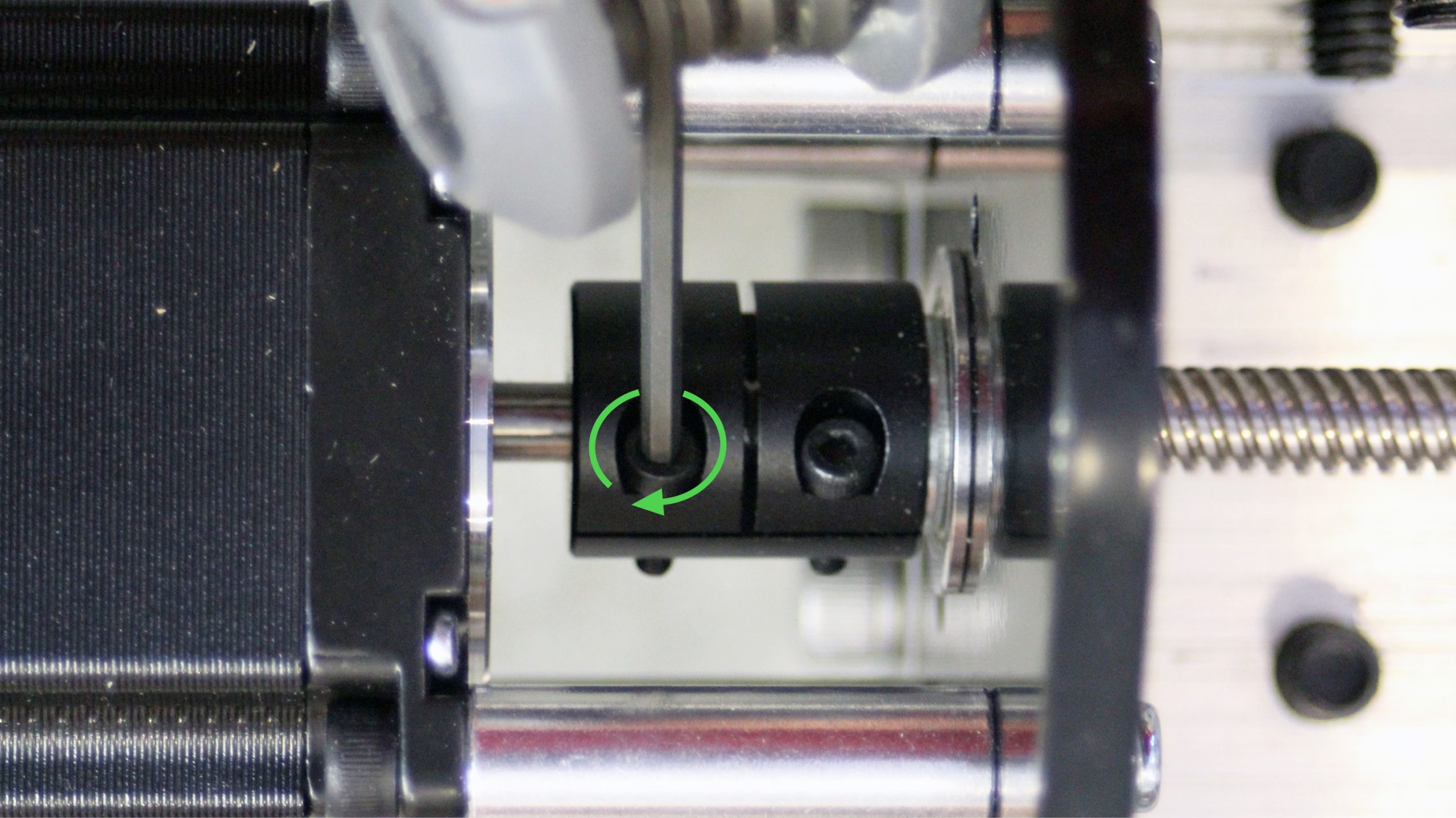
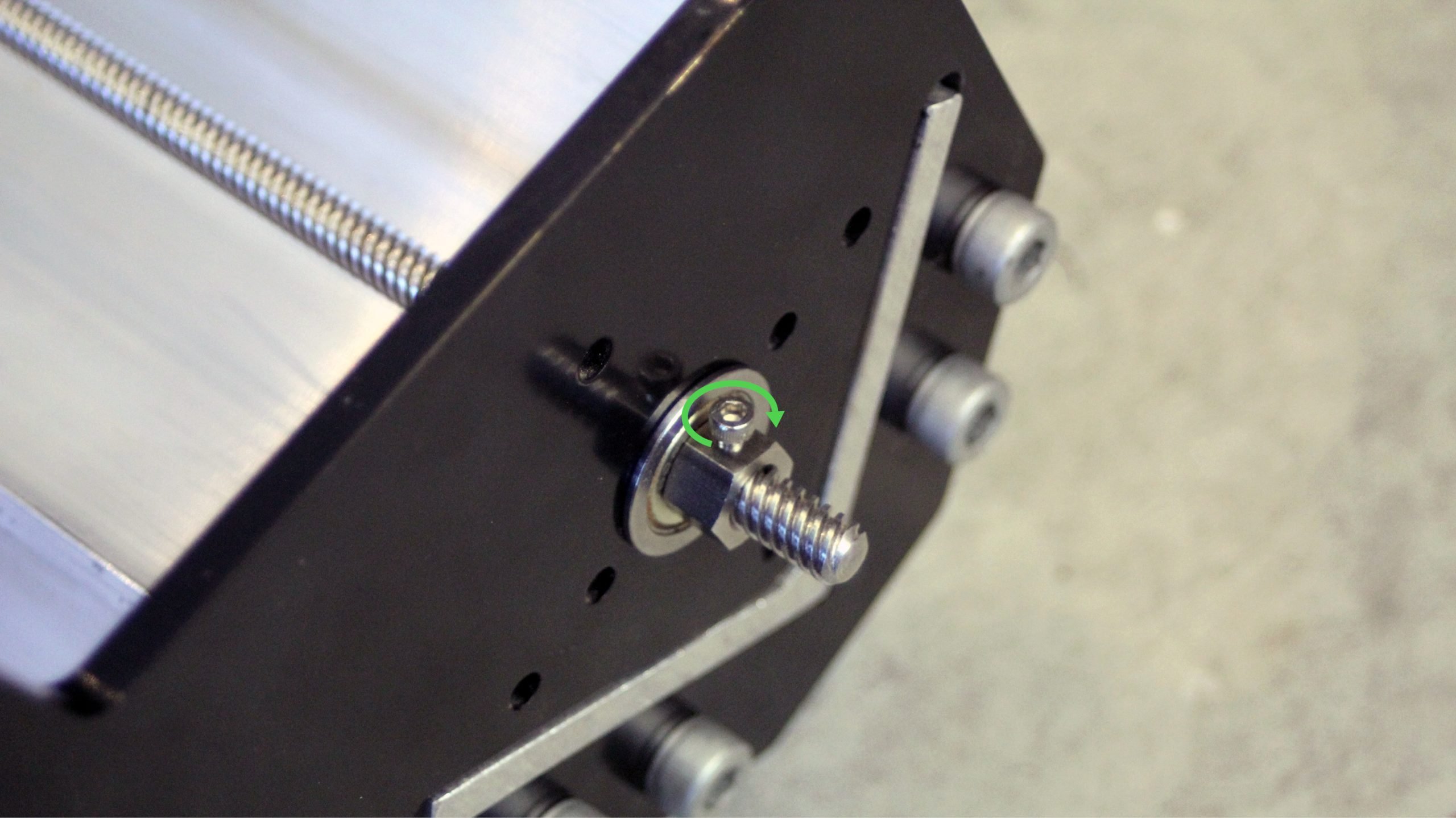
Once you’re satisfied that the lead screw well mounted, you can revisit the X-axis motor coupler to finally tighten the set screw on the motor shaft side to properly couple the motor to the lead screw (pictured).