

The following pages in the assembly section will guide you through how all the parts will fit together to make your LongMill. You should find that each major step is self-explanatory, but the required parts and quantities will still be written as an additional reference.
The LongMill comes with a specialized wrench which will assist you when putting your machine together and act as a dedicated maintenance tool once your machine is in operation. After you’ve opened the main box, you’ll find this wrench in the small white box accompanied by our Welcome letter and some stickers. One of these stickers shows Louis sitting atop a LongMill; Andy’s dog and our unofficial mascot and CEO.
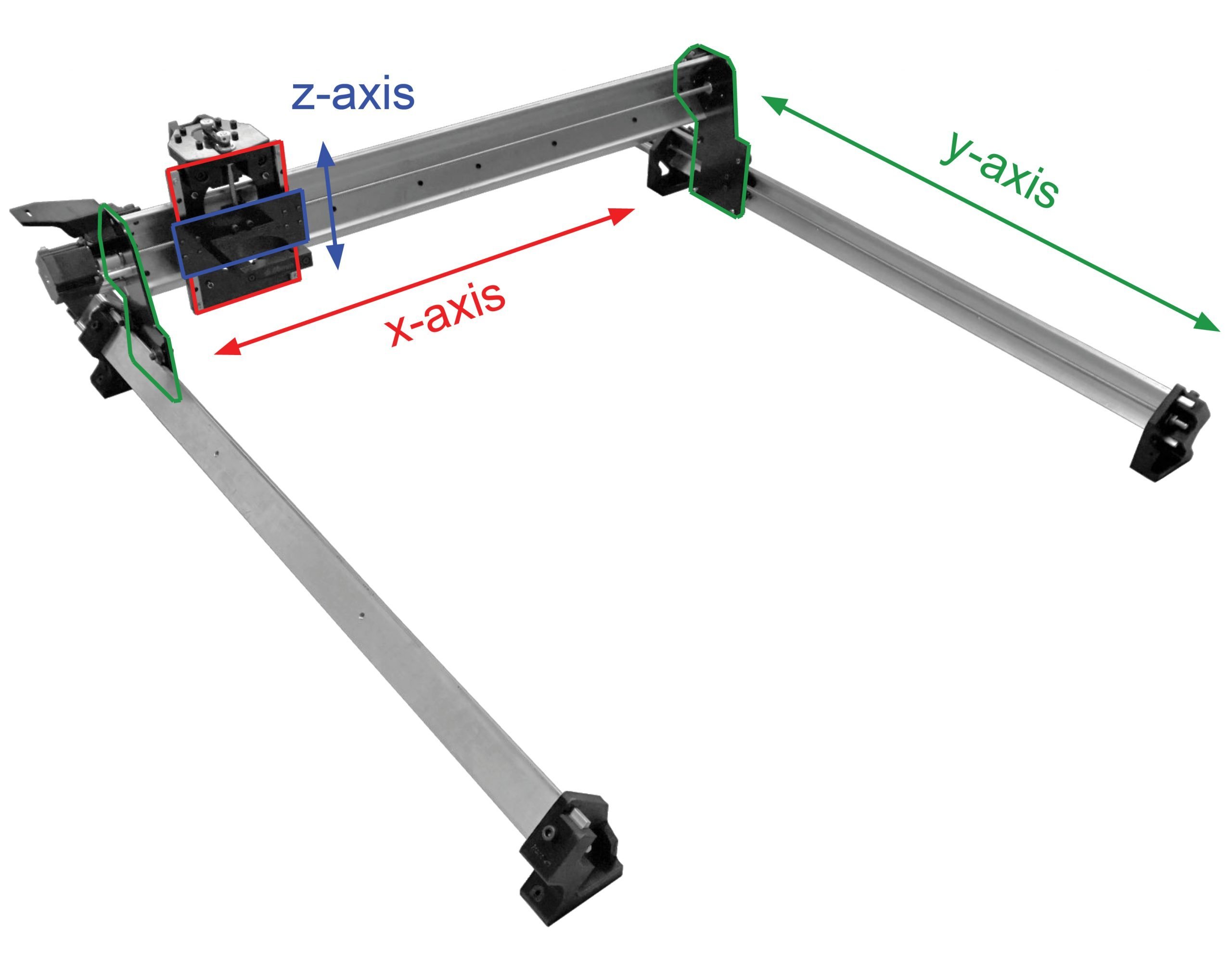
The diagram below shows the machine coordinate system of the LongMill. It’s able to move in its x, y, and z-directions due to the rails and respective gantries it has on each of those axes. We’ll start by assembling the x and z gantries which combine into a singular assembly; in the diagram these are coloured red and blue respectively.
Nut assemblies
Taking a look within your LongMill box, you should first look for a box at the bottom with a round orange sticker on it. Inside this box, you’ll find three hardware bags which are distinguishable by their sticker colour.
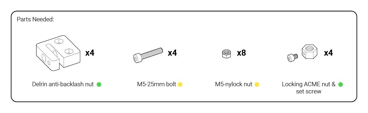
For this first step, we’ll be using some of the hardware contained within the bags with the green and yellow stickers. In the yellow bag you’ll find a bag labelled for ‘M5-nylock nuts’ and another for ‘M5-25mm’ bolts, this is the M5 hardware you need. The green dotted bag will also have a bag of interest within it which contains 4 rectangular plastic blocks, grab this as we’ll be preparing these blocks for installing onto the XZ-axis gantry and eventually on the Y-axis as well.
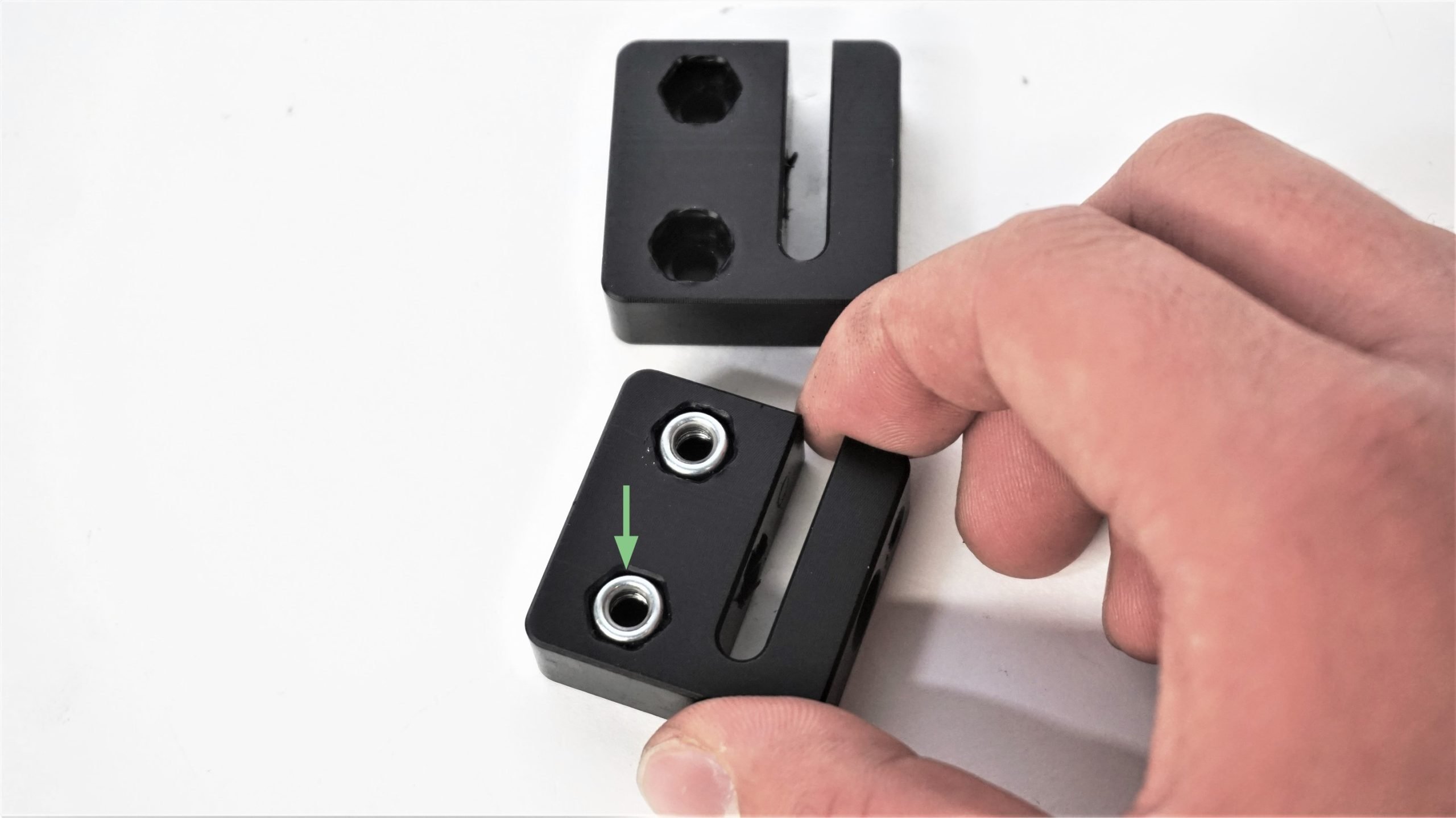
Start by pressing the M5-nylock nuts into the hexagonal cutouts. Make sure that you point the round end of the nut towards you, as you want the first part of the thread to be metal before your bolt gets to the nylon locking part.
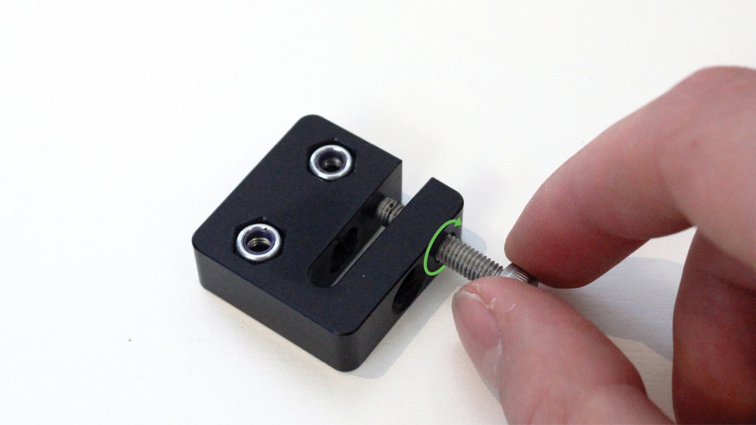
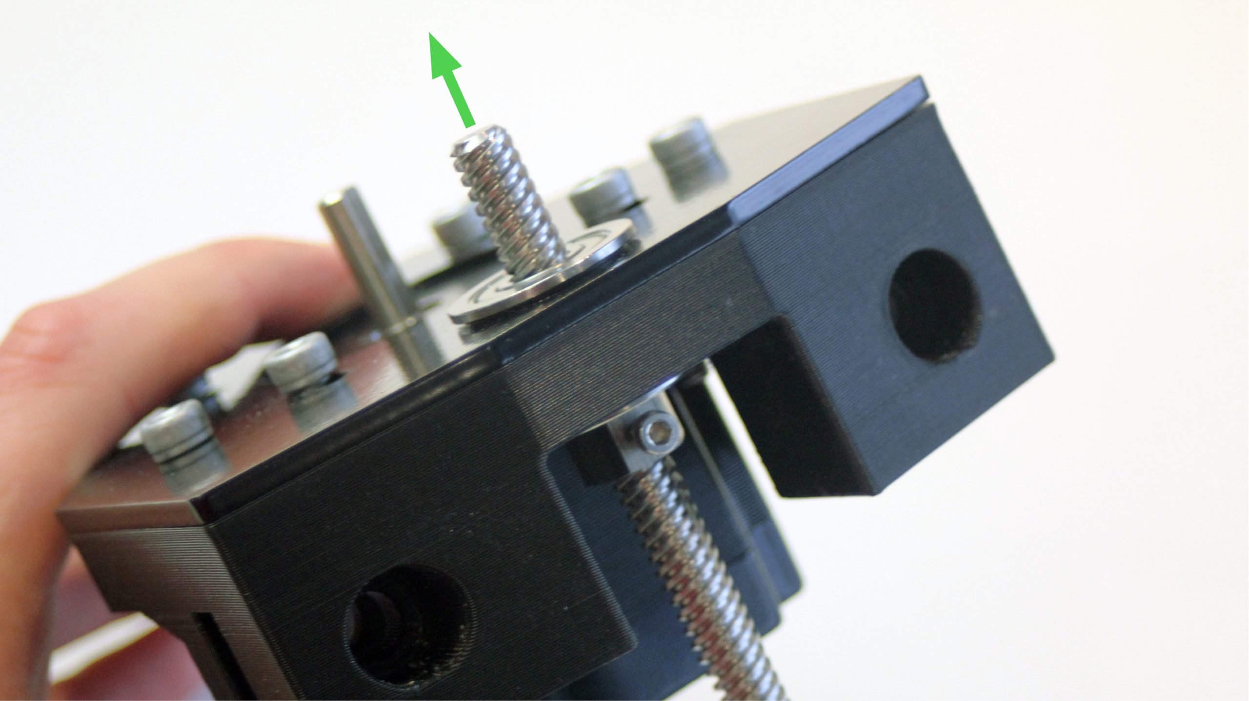
Next, put an M5-25mm screw into the threaded hole on each block. This screw will be used to tension your Delrin anti-backlash nut to the lead screw later.
Looking back to the green bag, you should find a bag within it that contains 4 large nuts and some small screws. Take the contents out and loosely thread all the set screws into the nuts by about 2.5 turns (for now). Please note that in some versions of the kit, the nuts may be made from brass.
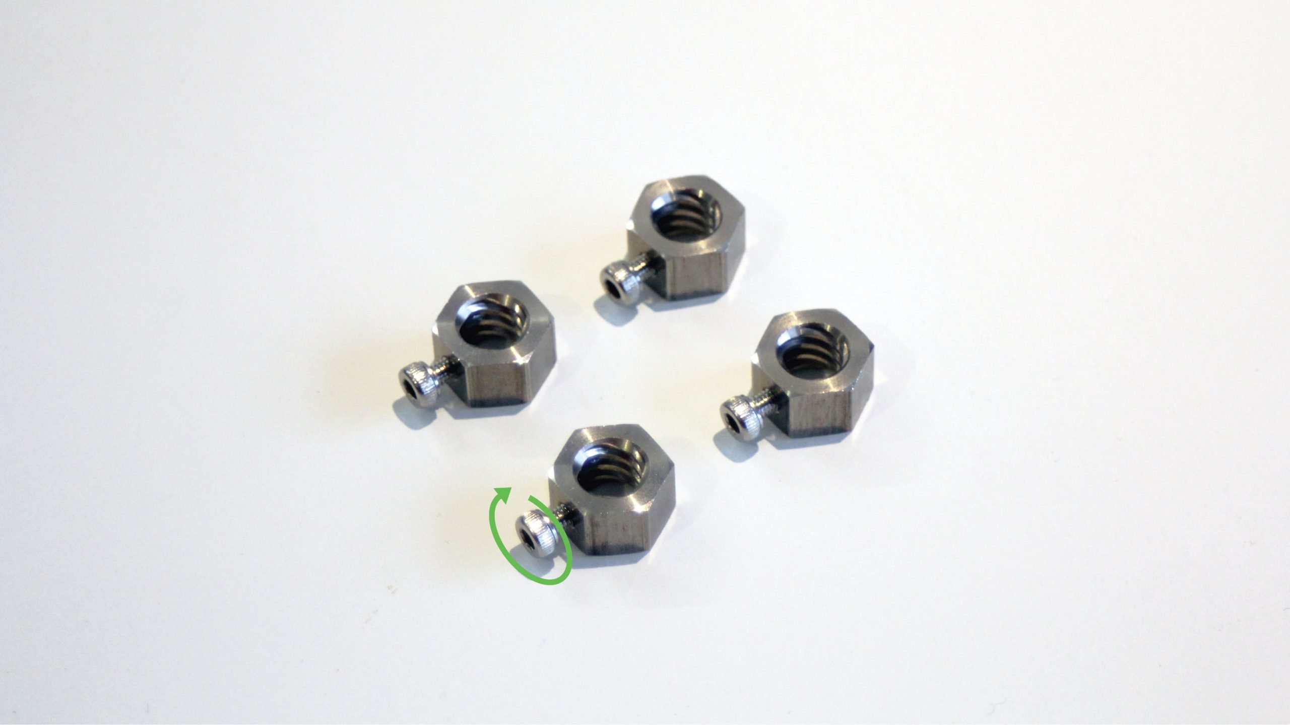
Prepare four sets of both these assemblies and set them aside for later.
Z-axis motor sub-assembly
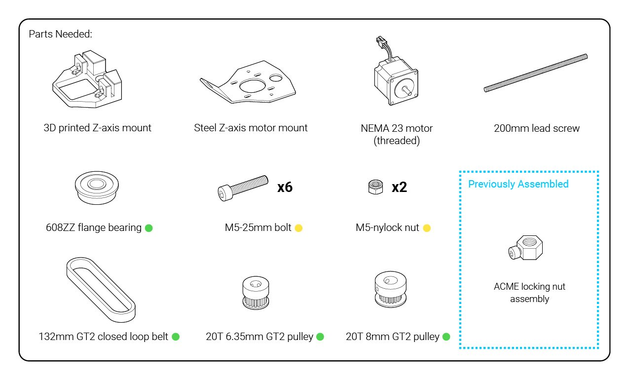
Keep your M5 hardware nearby. Look back into the green bag to get the bag filled with flange bearings, and another containing two pulleys and a belt. In the orange-dotted box you’ll want to grab the bubble-wrapped steel plate, and turning to the identical-looking green-dotted box you’ll want to get the plastic Z-axis mount. Inside the short, wide box you’ll find the stepper motors and their cables; you need the one that is specifically labelled on the back to be threaded.

Start off by pushing in two M5-nylock nuts into the hexagonal holes in the 3D printed Z-axis mount. These will be used to mount the steel Z-axis motor mount.

To the side, put the steel plate on the top of the motor, ensuring that its cable bundle is facing away from the middle-sized hole on the plate. Loosely thread four M5-25mm bolts through the slots and the motor, the plate slots may be a little tight but that’s fine; we’ll be adjusting this part and re-tightening the bolts later in the assembly.

Fit the motor and plate assembly into the 3D printed Z-axis mount. If it doesn’t slide in easily, try sliding the motor all the way forward, and tilting the plate back slightly. You’ll know they’re aligned when their profiles match and they lay flush against each other.

Get the bag with bearings in it and use two when pressing them into the top and bottom bore on your assembly. You should be able to get them on easily with your thumbs. If you find resistance, try adjusting the steel plate so that the bores on the plastic and steel line up.
Both flanges of each bearing should sit flush with no gap.


Using two more of the same bolts, secure the plate and the 3D printed part together. These should thread all the way through to the nuts that you placed earlier in the plastic mount.

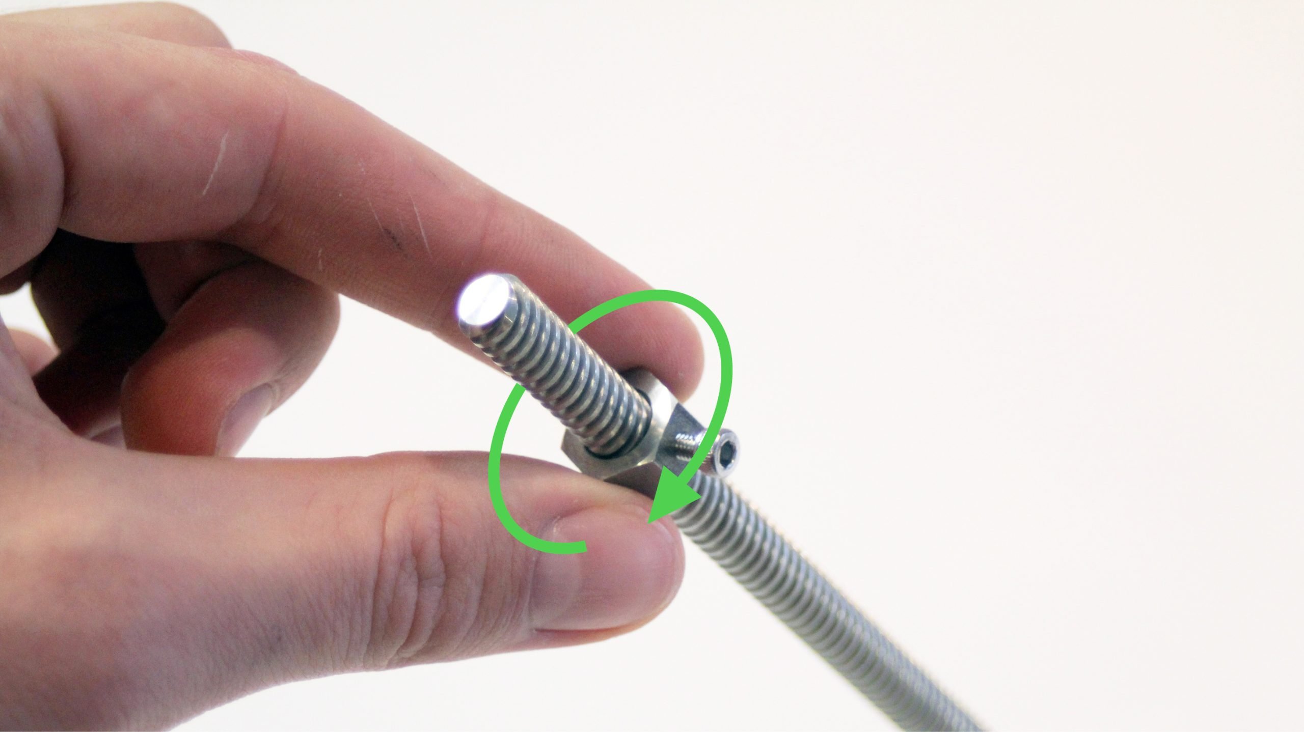
The long, heavy box contains the rails, drag chains, and lead screws. Cut it open, remove the protective cardboard and shrink-wrap, and inside the bundle of lead screws you should be able to locate a very short lead screw which is what’s used for the Z-axis. With this in hand, get one of the ACME locking nut assemblies that you’d made before and thread the nut about 1.5 inches onto the lead screw. Make sure the nut still has its M3 set-screw.
Next, slide the short end of the lead screw up through the flange bearings.
The clearance between the bearing and the lead screw can be quite tight. Ensure that you are putting the bearing in straight before applying force to slide the bearing on. Some customers may need to wiggle the lead screw around or tap the lead screw with a mallet to get the bearing in all of the way.
Get the bag with a belt and two pulleys. You’ll find that only one of the pulleys will be able to fit over the lead screw but you’ll first have to unscrew the set screws a little with the included Allen key. Orient the pulley so that the base is flush with the end of the lead screw then tighten the screws into place.


Once the pulley is secure, twist the ACME locking nut in from the other side so that the pulley and the nut are sandwiching the two bearings. Once in place, tighten the M3 screw on the nut to hold it in place and ensure there’s no play up and down. Adjust and tighten if necessary.

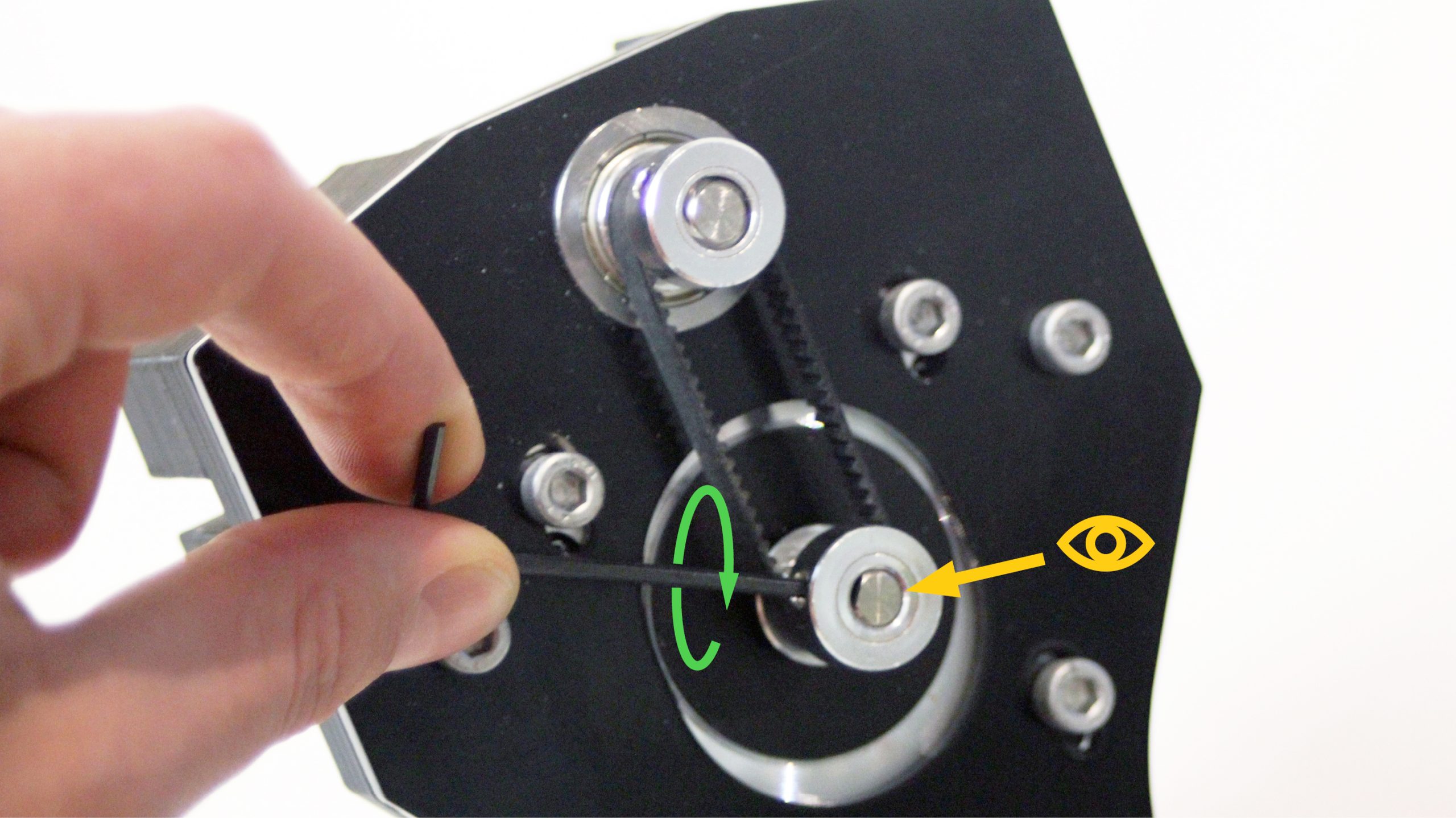
To put the belt into place: loosen the second pulley set screw, wrap the belt around it, slide the motor toward the lead screw, then wrap the belt around the first pulley and install the second pulley onto the motor shaft.
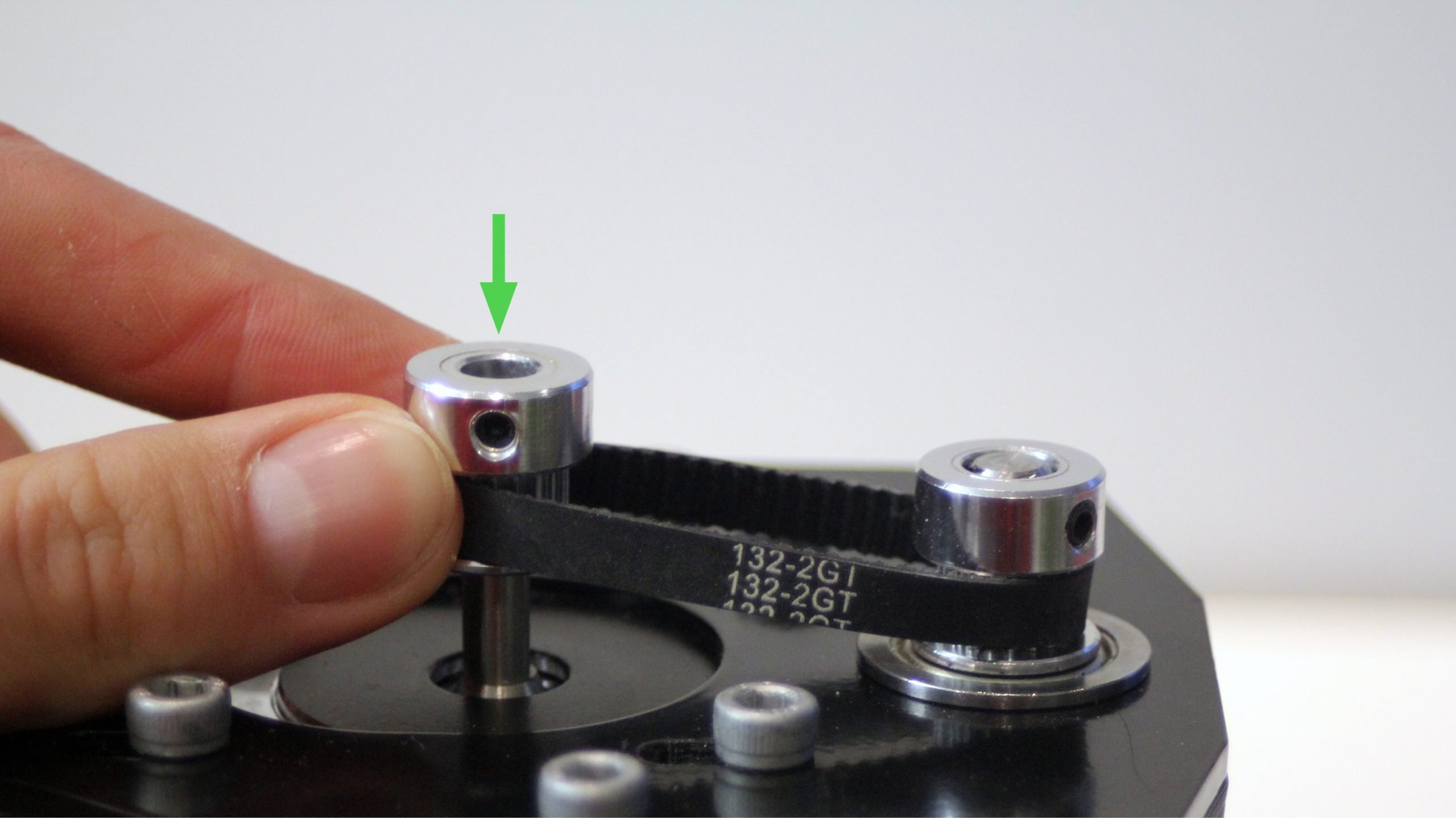
The base of the second pulley should be flush with the top of the motor shaft when tightened. Make sure to line up one of the set screws with the flat part of the motor shaft to provide extra holding strength (as shown in the photo).
Next, make sure that the belt is tight around the two pulleys by pulling back the motor in the slot then tightening the M5 bolts that are holding it in place.

XZ-axis gantries sub-assembly
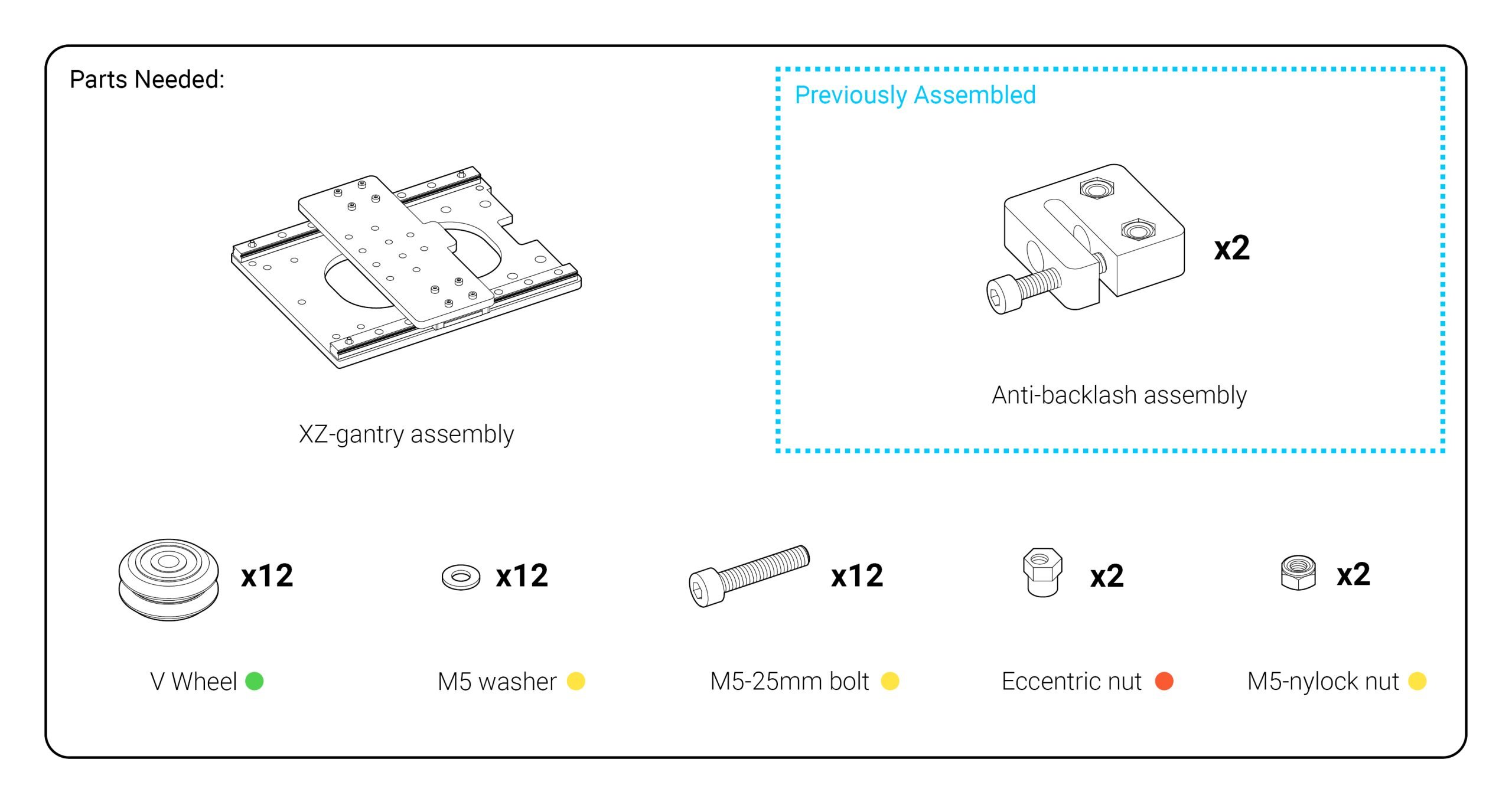
You should find the XZ-gantry assembly in a labelled bubble mailer. Once you take it out, you’ll see there’s a small steel plate (z-gantry) attached to big steel plate (x-gantry) via two sliding rails. First, check that the movement of your z-gantry is smooth by moving it up and down by hand. There should be no binding and the gantry should move relatively smoothly.

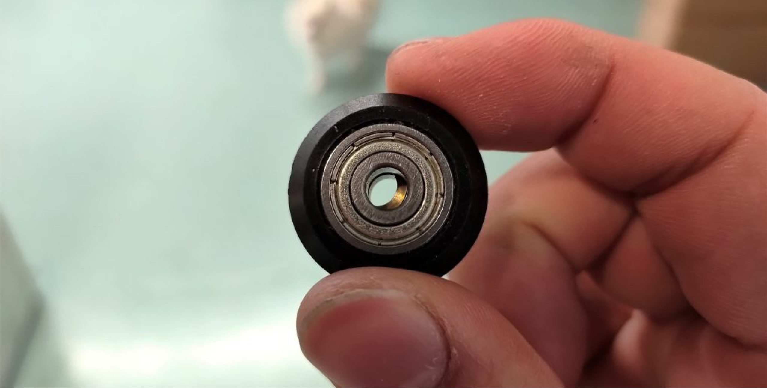
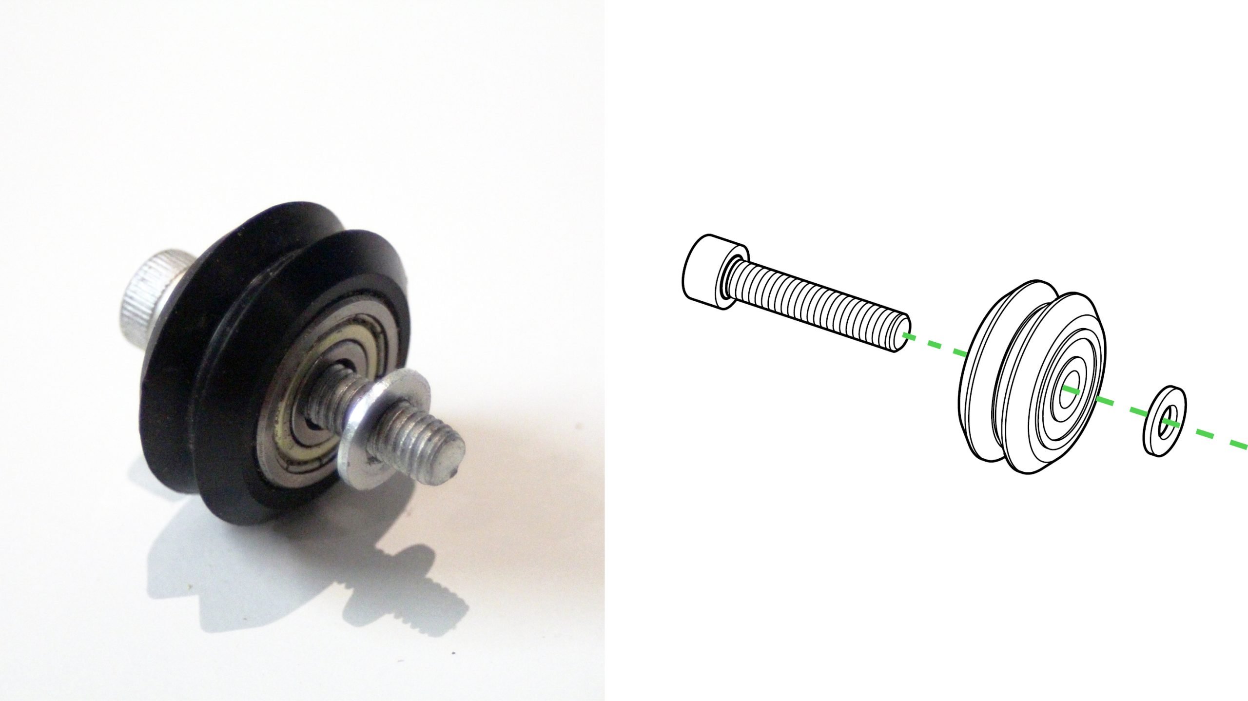
Set the assembly to the side and get the green and yellow bags. In addition to the M5 bolts you have already used, the yellow bag should contain M5 washers. Inside the green bag is a set of 12 Delrin wheels. Spilling out the wheels, if you look down the center-hole you’ll notice that they have a bronze-coloured inner ring which can sometimes off-center (pictured). Use the included small Allen key from the belt assembly to move the inner ring back into the center.
After this, make a small assembly with the wheel going onto the bolt, followed by a washer (pictured). There will be 12 of these sets total. It’s very important that the washer is in the correct place, as it keeps the wheel from rubbing against the gantry, as well as providing the correct spacing between the gantry and the lead screw. You’ll need four of these assembled sets for now.
You’ll also need two of the medium-sized M5 nuts from the last step and you’ll also need to grab eccentric nuts from the hardware bag labelled with an orange dot. These come in a small bag of 6 and are very odd looking so they should be easy to identify.
If you move the z-gantry to the middle on the XZ-gantry assembly, you’ll notice 4 holes in a rectangular formation on the large steel plate. The 4 sets of wheel assemblies go into these holes from behind, the bottom two using a regular nut and the top two using an eccentric nut. Start by fitting the eccentric nuts into the top pair of holes. The round part of the bore should sit inside of the hole, with the hex part facing out.
If you have a hard time getting the nuts in, we recommend tapping them in with the back of a screwdriver or other dull object. This will help clear the excess paint that might still remain in the hole.

Twist two of the v-wheel sets into the eccentric nuts from the other side. These don’t need to be tight yet, so just attach them by hand for now.

Now attach the bottom two v-wheel sets. These attach with regular M5-nylock nuts and need to be tightly fastened into place. You can do this with a size 4 Allen key and the included 8mm wrench.


Once complete, all of your wheels will be facing the backside of your gantry. Check to make sure that each wheel turns smoothly.

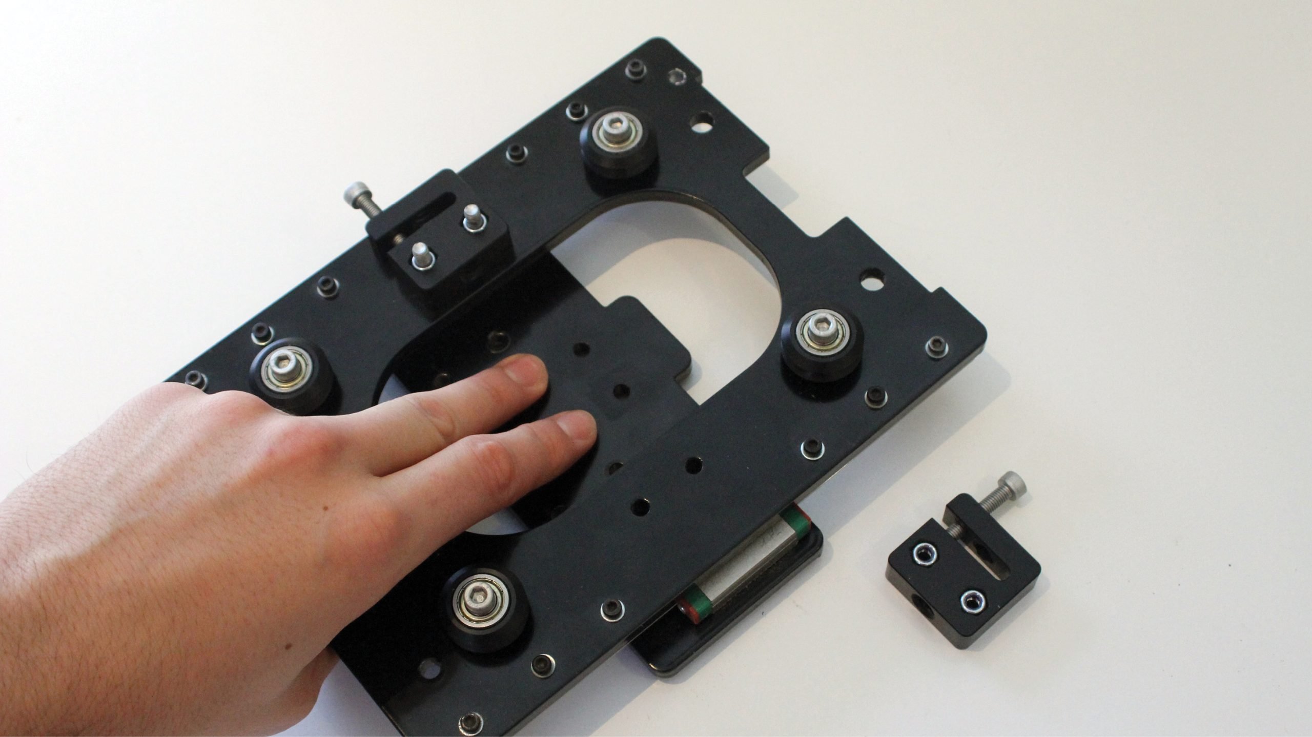
There are two anti-backlash assemblies that attach to the XZ-gantry assembly. The first one we will assemble goes on the X-gantry.

Use two M5-25mm bolts (the same ones used to make the v-wheel sets) to mount the nut block. Make sure that the M5 nuts are facing outwards (pictured) so that you can see them. The block shouldn’t be tightened down really hard, just fasten it until it’s snug.

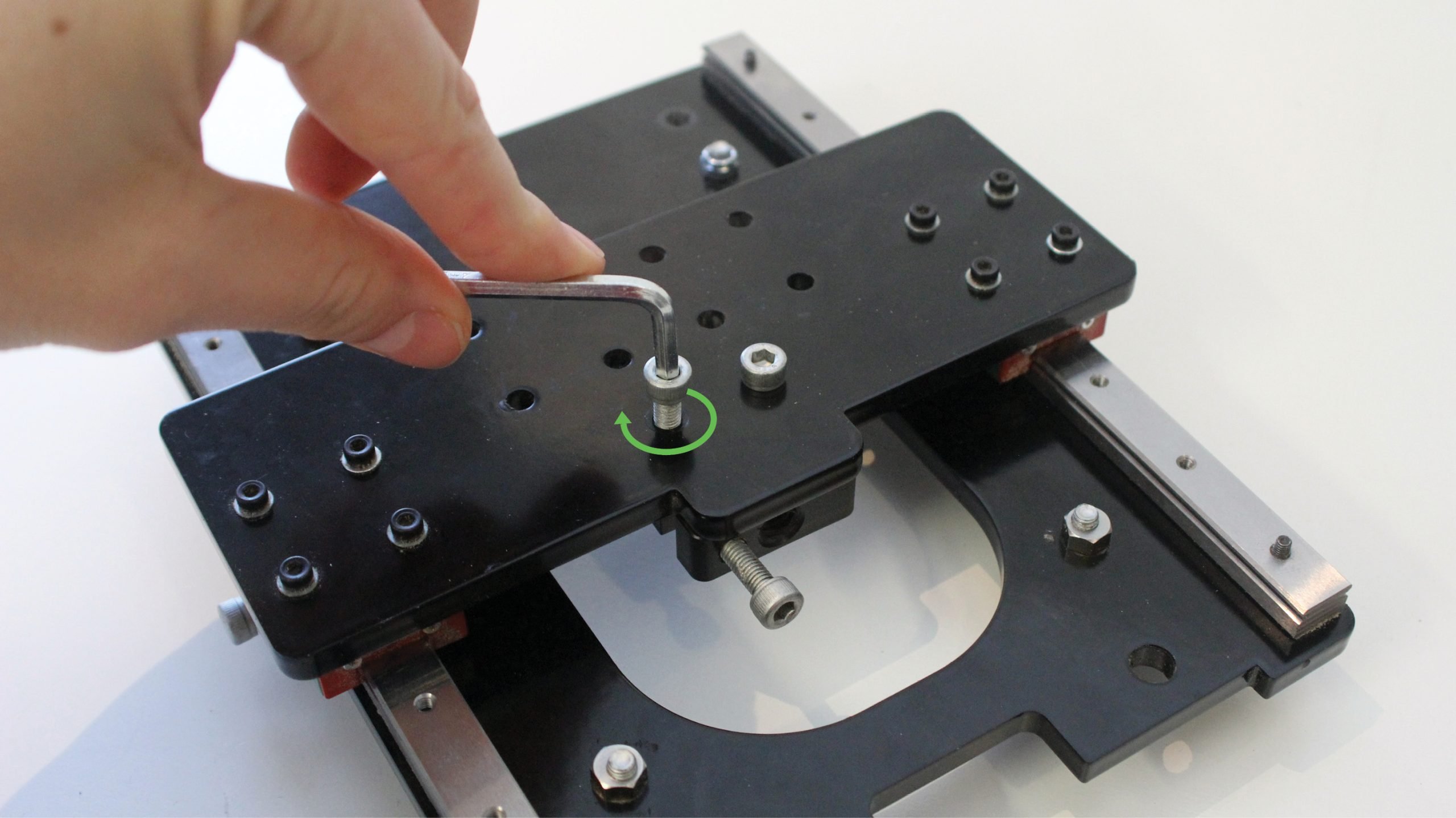
Now we’ll do the same process on the Z-axis on the two holes shown.
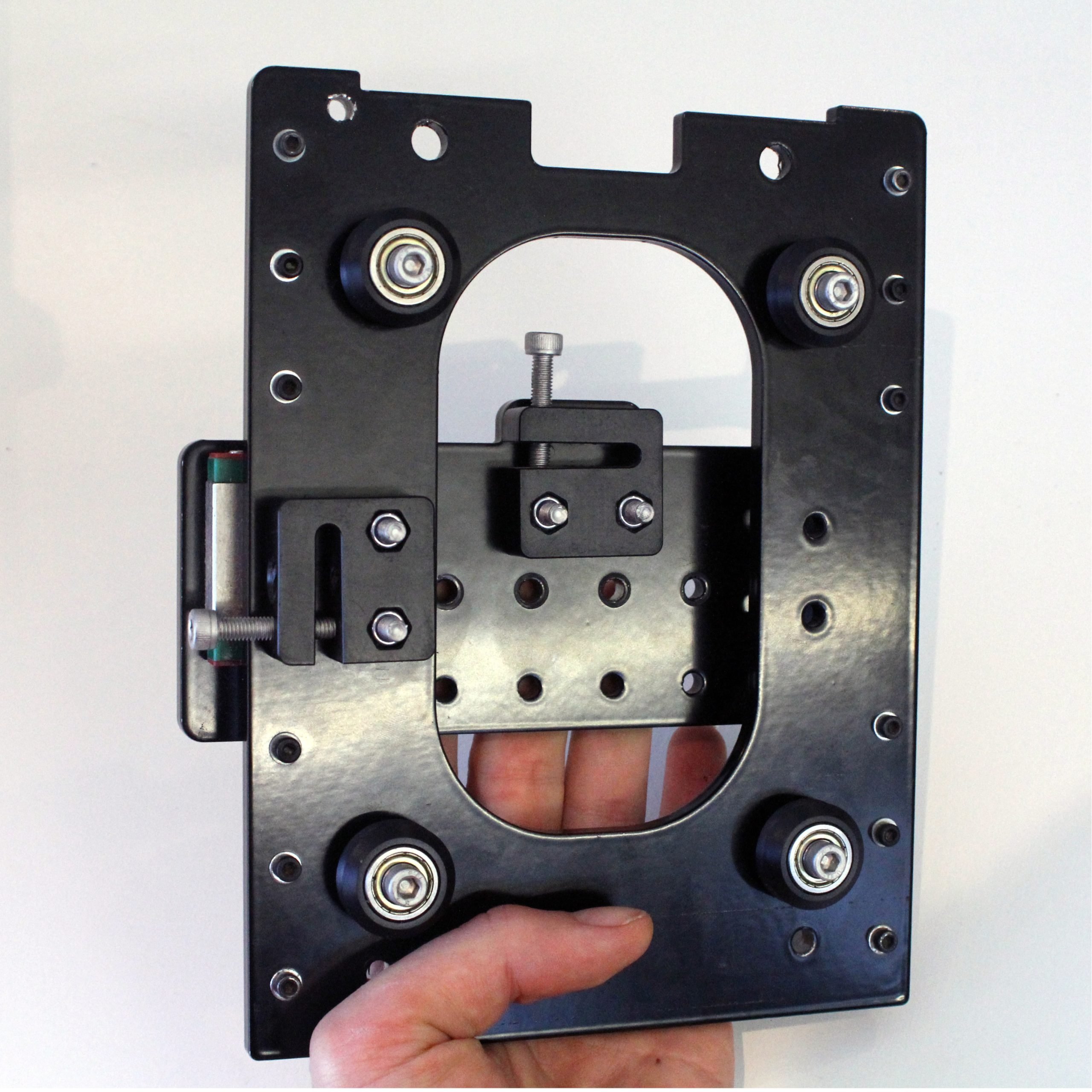
The completed assembly should look like this.
Connecting the two major sub-assemblies
Get the motor sub-assembly from before. Holding it in one hand, and the gantry sub-assembly in the other, line up the lead screw from the motor assembly with the nut block of the gantry assembly. If you use your fingers to turn the lead screw, it will go into the nut. The plastic mount should be coming in from the side of the steel plate which has a rectangular notch cut out.
If you have trouble threading in your lead screw into the Delrin anti-backlash nut, please check our troubleshooting guide for additional help adjusting your anti-backlash nut.
 is completely loose.")
Continue turning the lead screw until the plastic, Z-axis mount is fully seated into the top of the plate and you can see the holes lining up.

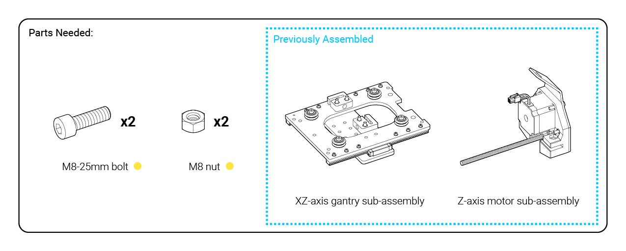
Get the M8 nuts and M8-25mm bolts from the yellow hardware bag; you’ll use a pair of each to fasten these two assemblies together. Take the two large nuts and push them into the back of the plastic Z-axis mount. If the nut fit is a little tight, then you can use a size 6 Allen key or other tool to press it into place.
Now with the two long bolts, slide them in from front through the two holes in the plastic mount. Turn them into place with a size 6 Allen key to secure the two assemblies together; the bolts should be reasonably tight.

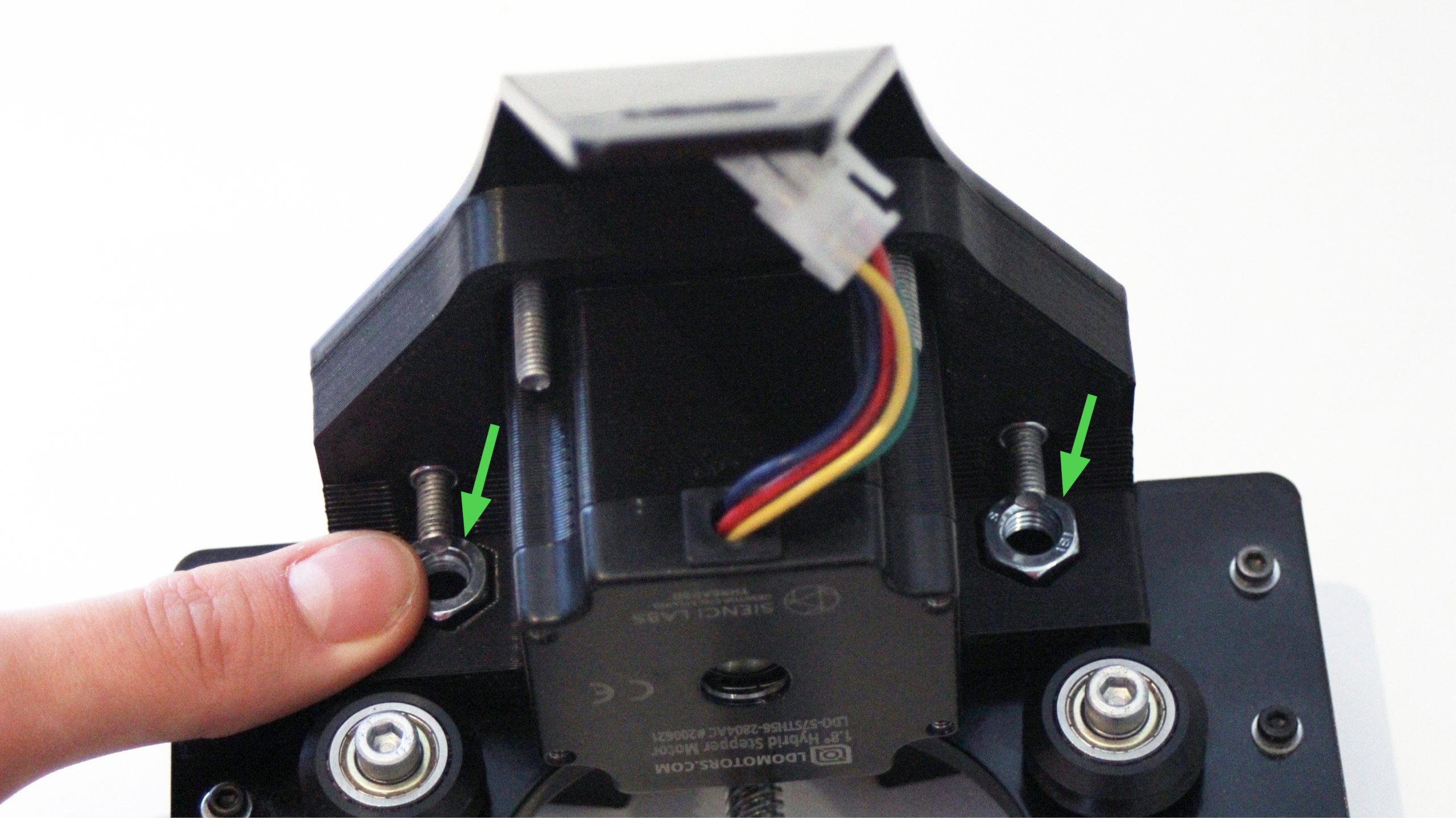
Your assembly should now look like this.
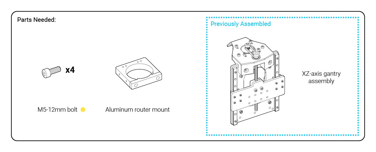
Attaching the router mount
UPDATE
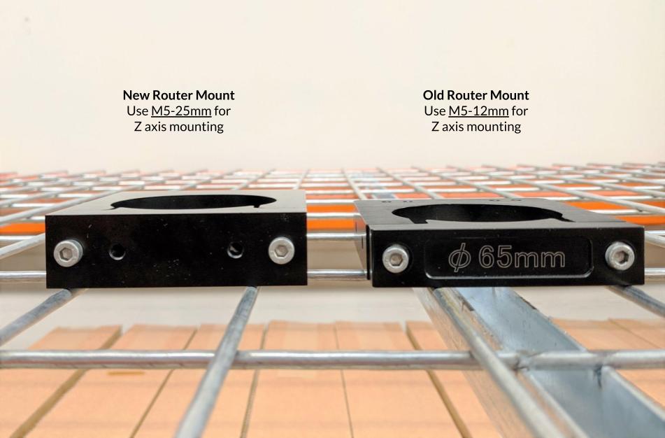
If you have a hardware bag marked “Batch 5”, please substitute M5-25mm bolts for assembling the router mount in this step. The newest version of our router mount has been designed to work with longer M5 hardware. To identify which router mount you have, please check the image below:
Notice that the Z-axis gantry plate has two sets of four holes; these are positioned for mounting the aluminum router mount at two different heights. The lower set of holes will allow your router to gain more cutting depth, whereas the upper set will mount the router more rigidly and allow for the full height clearance. Use the upper set of holes to start.
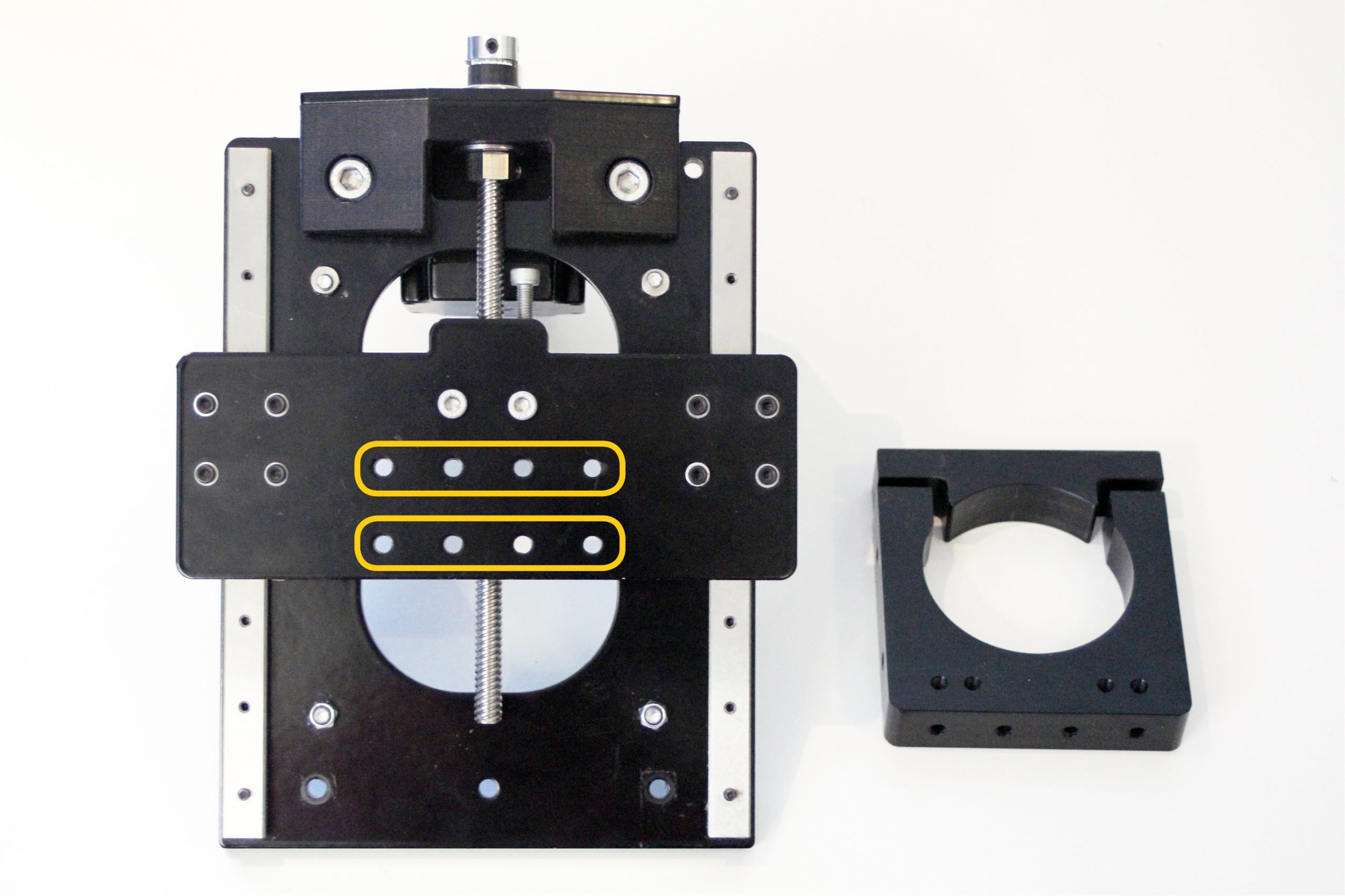
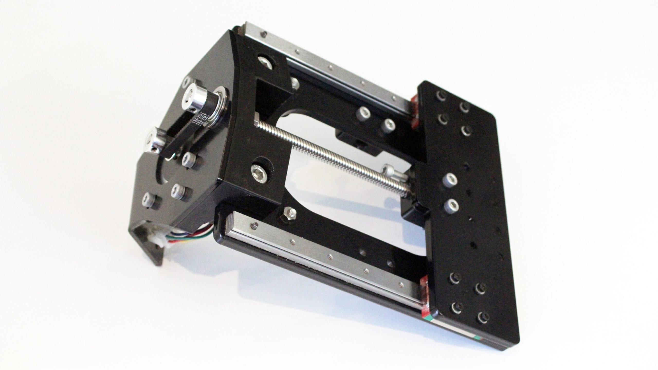
Find your machine’s included aluminum router mount, it will be individually wrapped in paper and labelled appropriately (mount pictured). Also, find the M5-12mm bolts in the yellow hardware bag, these will be use to attach the aluminum mount.
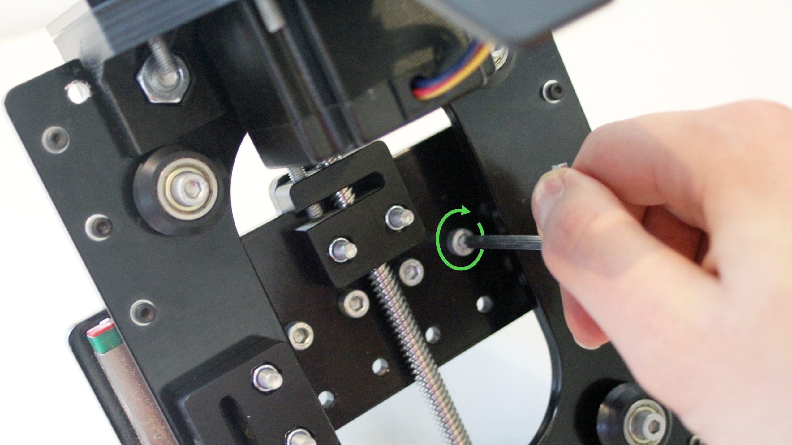
With the current assembly turned around (looking in from behind) you’ll be able to place the four shorter bolts into the upper set of holes. Holding the router mount up to the bolts, you should be able to fasten it into place with a size 4 Allen key.

Your final assembly should look like this. Congrats, you’ve completed the assembly of the XZ-Axis Gantry!
