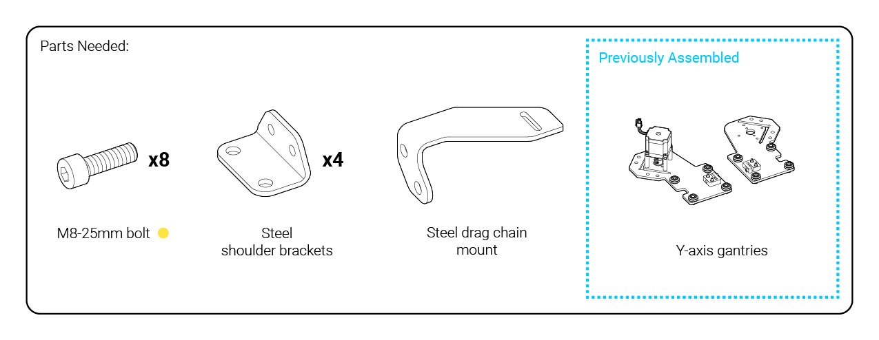
Y-axis gantries (wheels)
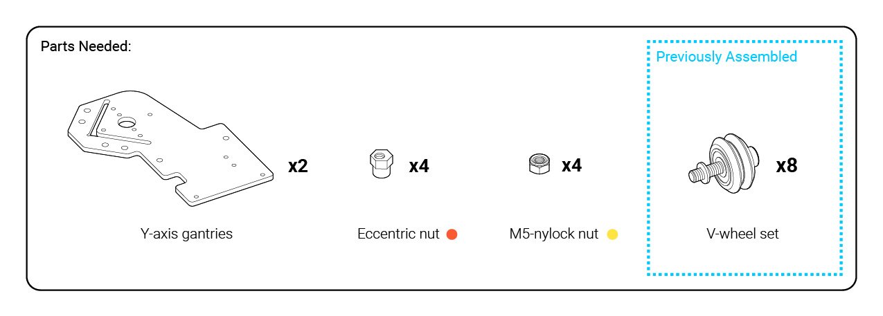
Grab the Y-axis gantries (wrapped in paper) and you’ll see four holes on each steel plate in a square formation. Add the wheel sub-assemblies to these holes just like how you did before, with the eccentric nuts placed as pictures and the nylock nuts on the two lower holes; make sure that one is assembled as the mirror of the other. Use a size 4 Allen key and the included 8mm wrench to tighten everything down, but leave the eccentric nuts slightly loose for now.
If you have a hard time getting the eccentric nuts in, we recommend tapping the nuts in with the back of a screwdriver or other dull object. This will help clear the excess paint that might still remain in the hole.


Y-axis gantries (anti-backlash)
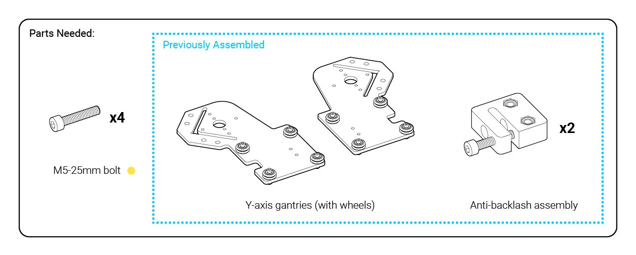
On the Y-axis plates, there are two holes for the anti-backlash assemblies to mount. Line up the plastic blocks and secure them to the plate using the same medium-sized bolts that were used for the wheels. The blocks should be mounted on the same side as the v-wheels, and have the tensioning screw facing outwards.


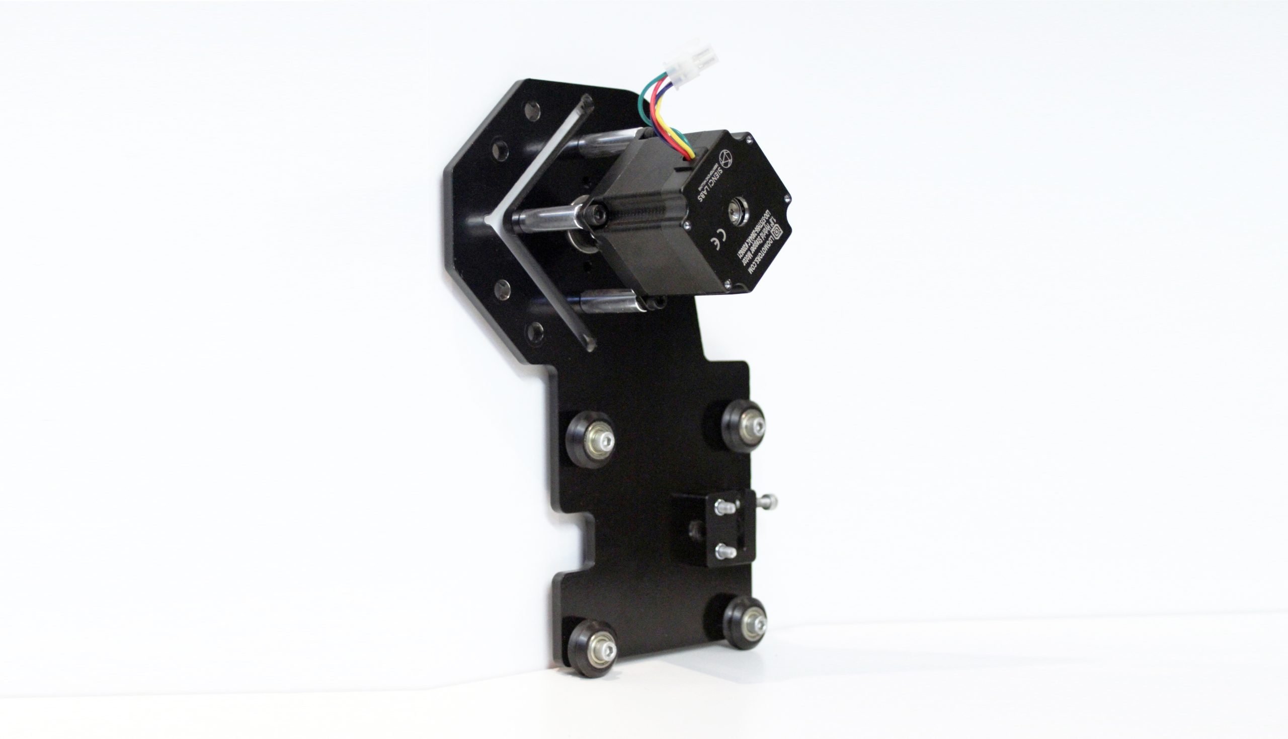
Mounting the X-axis motor to the left plate
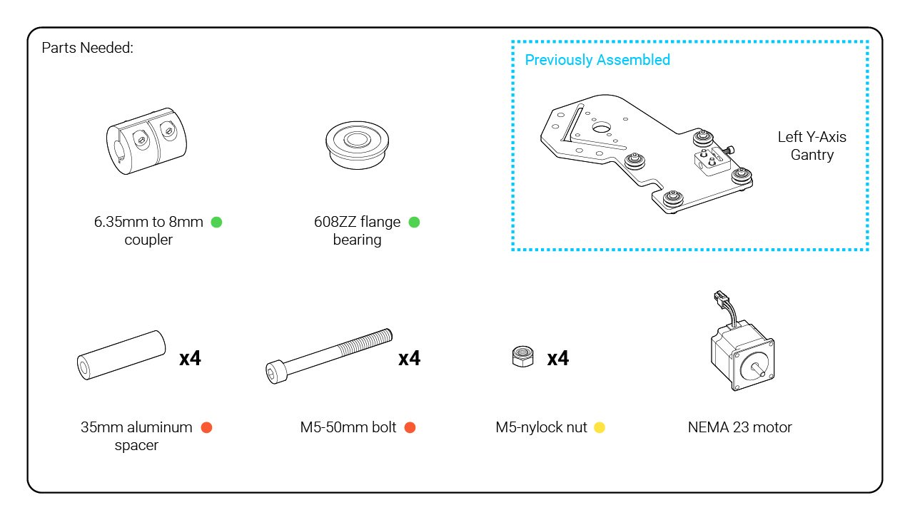
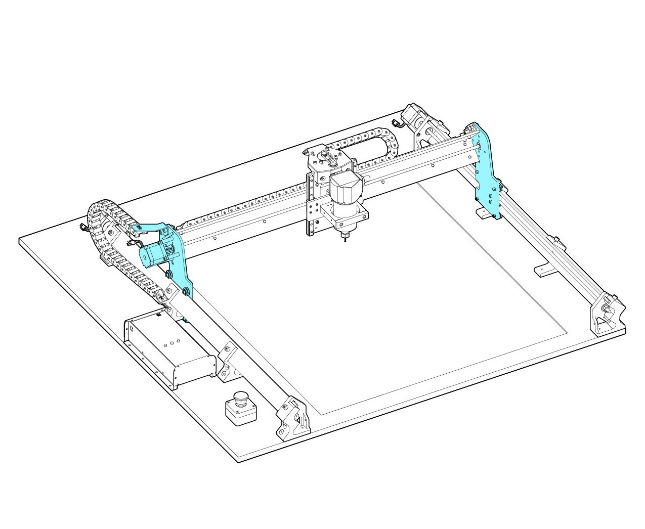
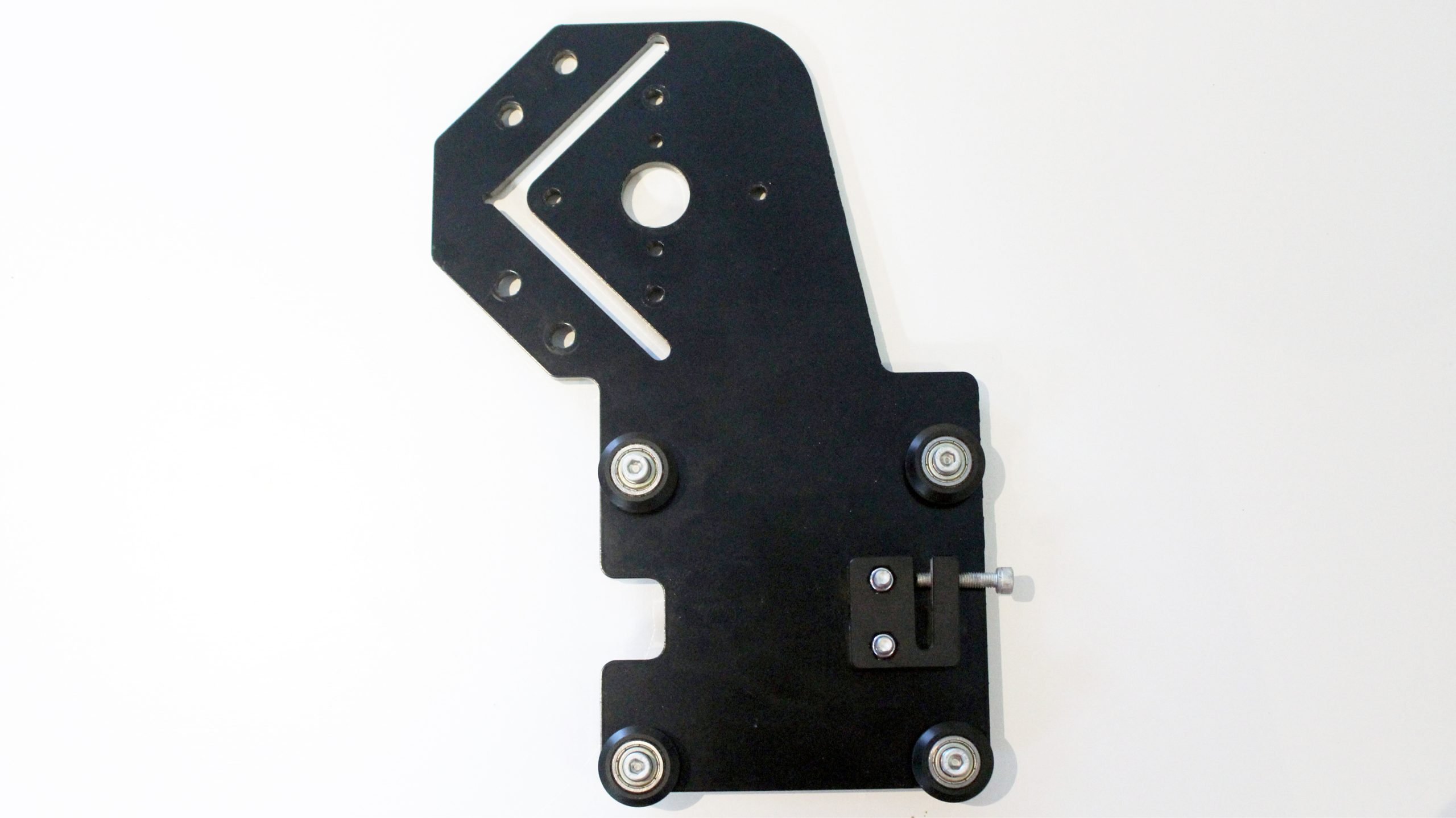
Make sure you have grabbed the correct gantry (pictured below).
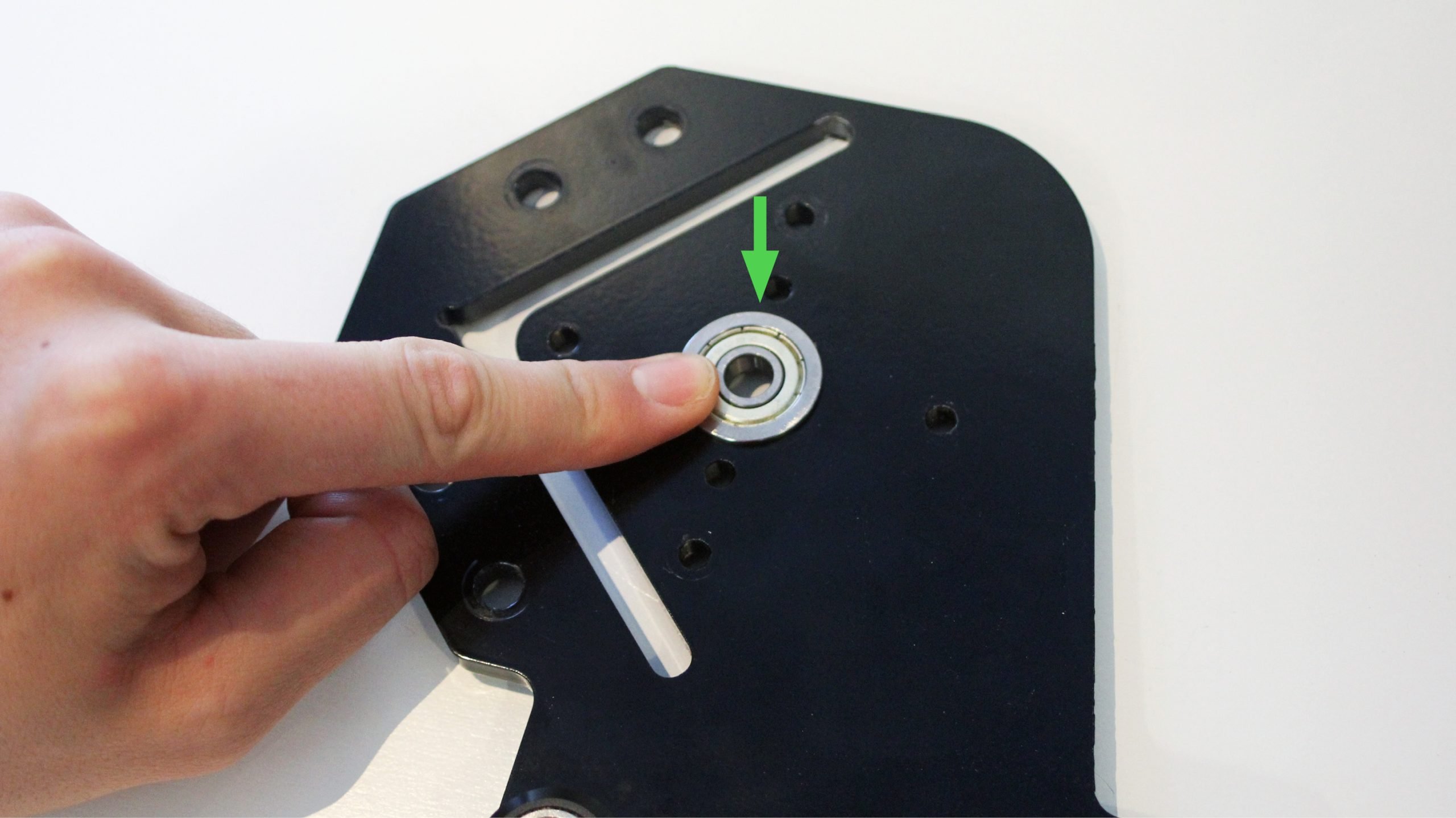
We will put a 608ZZ flange bearing into the hole.
Get a motor, the M5 nylock nuts from before, and the bag of long bolts (M5-50) and aluminum spacers from the orange bag. You will also need a coupler and bearing for this assembly, found in the green bag.
Start off by sliding the coupler onto the motor shaft, making sure you have the smaller hole sliding onto the shaft and the larger hole facing out. You may have to loosen the set screws on the coupler if it doesn’t slide on easily. Then put the long M5 bolts onto the motor, followed by the spacers.

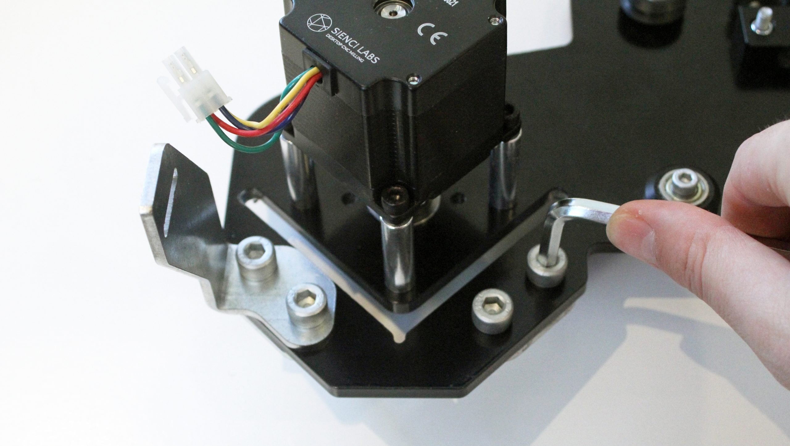
Carefully line up the screws into the four holes in the Y-axis gantry. Drop the motor, bolts, and standoffs into place. Take note of the position of the white motor connector in terms of its rotation and what side of the plate you are mounting it onto (the side with the wheels).


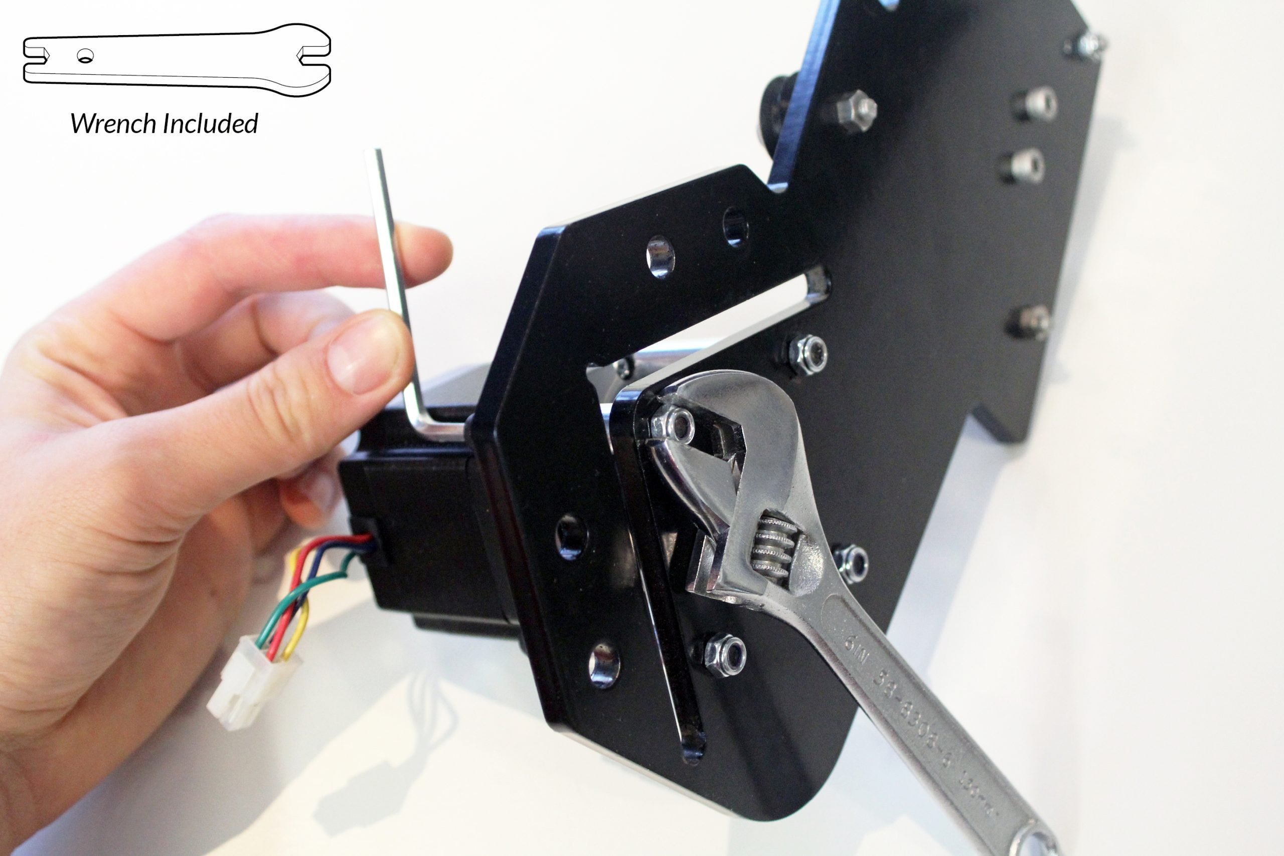
Use the four M5-nylock nuts to secure the plate-side of the M5 bolts. This requires a size 4 Allen key and the 8mm wrench. If it’s easier, start by finger-tightening all four nuts to keep everything in place before using the pliers to finish tightening.
Once everything is finished getting put together, it should look like this:
Attaching the shoulder brackets
UPDATE
If you have a hardware bag marked “Batch 5” please substitute M8-16mm bolts instead of M8-25mm bolts for this step. Please follow the exact same assembly process in this step but use M8-16mm bolts for mounting the shoulder brackets and drag chain mounts.
Get the four steel L-shaped ‘shoulder’ parts from the green box of plastic parts next. These attach two to each gantry using the M8-25mm bolts from the orange bag. Line the tapered sides of the brackets up against the edge of the inside face of the gantries (pictured) and then mount them in place using two bolts each. The bolts are long so start by turning them by hand and then finish securing them with a size 6 Allen key.

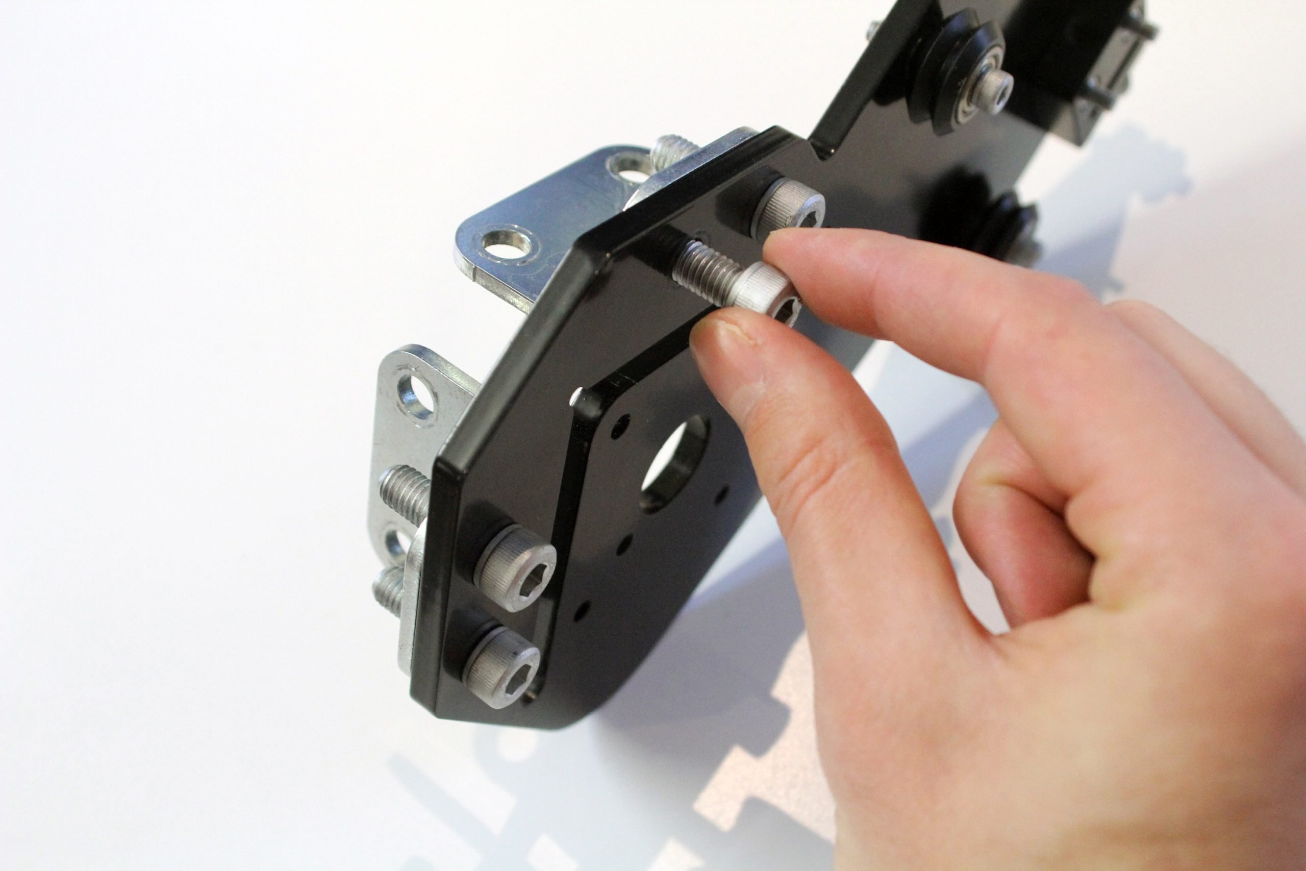
Do the same for the gantry with the motor, but this time adding the steel drag chain mount on the side with the bolt heads.