
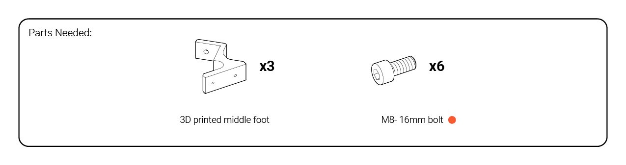
Feet sub-assemblies
The two Y-axis rails mount to the machine base via a handful of plastic feet which require a bit of assembly before-hand. Start off by finding the front and back pairs among the plastic parts (pictured). These parts can be distinguished by their ‘zig-zag-like’ pattern with a thick base and by the embossed lettering denoting their position on the machine (e.g. “Back left” and “Back right”).
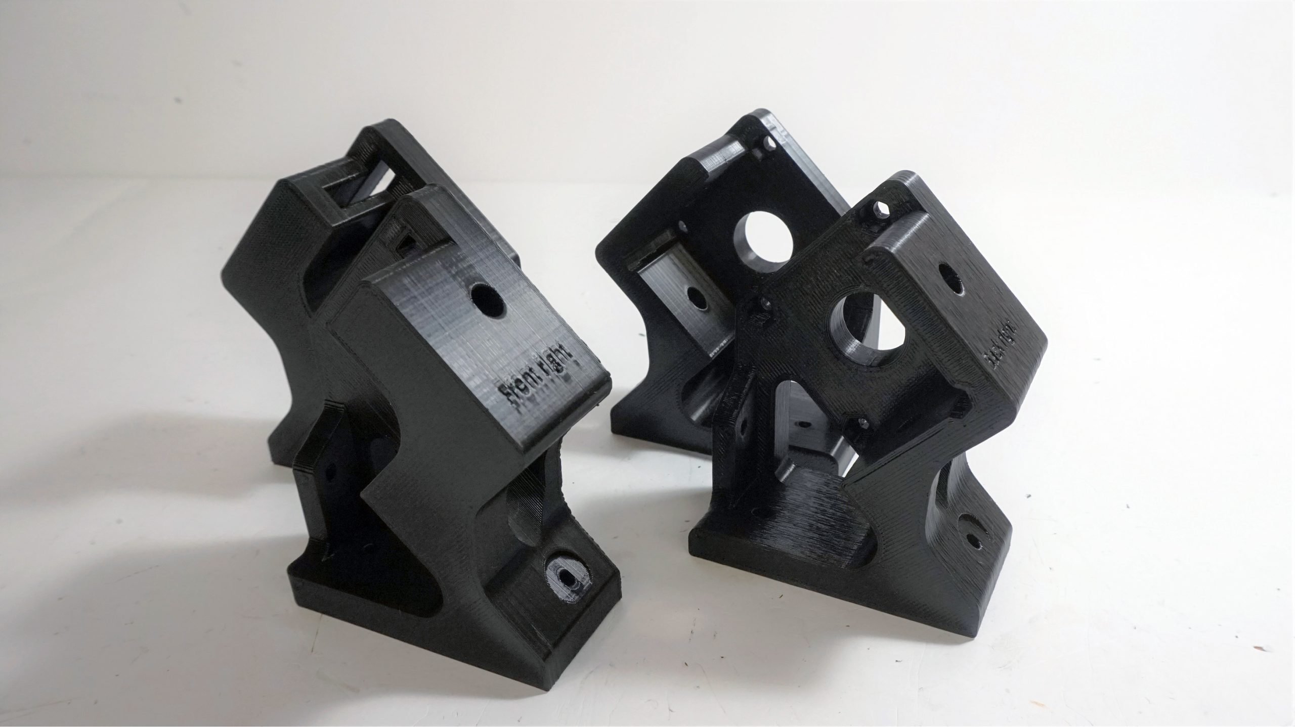
With the bearings still in hand from the last step, you’ll need to push one of them into each of the four feet. The front feet should have the bearings pushed in from the front, and the rear feet from the rear (pictured); make sure that you get the orientation right on these.
These bearings are meant to be quite a snug fit, so feel free to use a vise or a mallet against the outer flange of the bearing to get them properly seated into the feet. You’ll know they’re in all the way once the flange is completely flush with the surface.


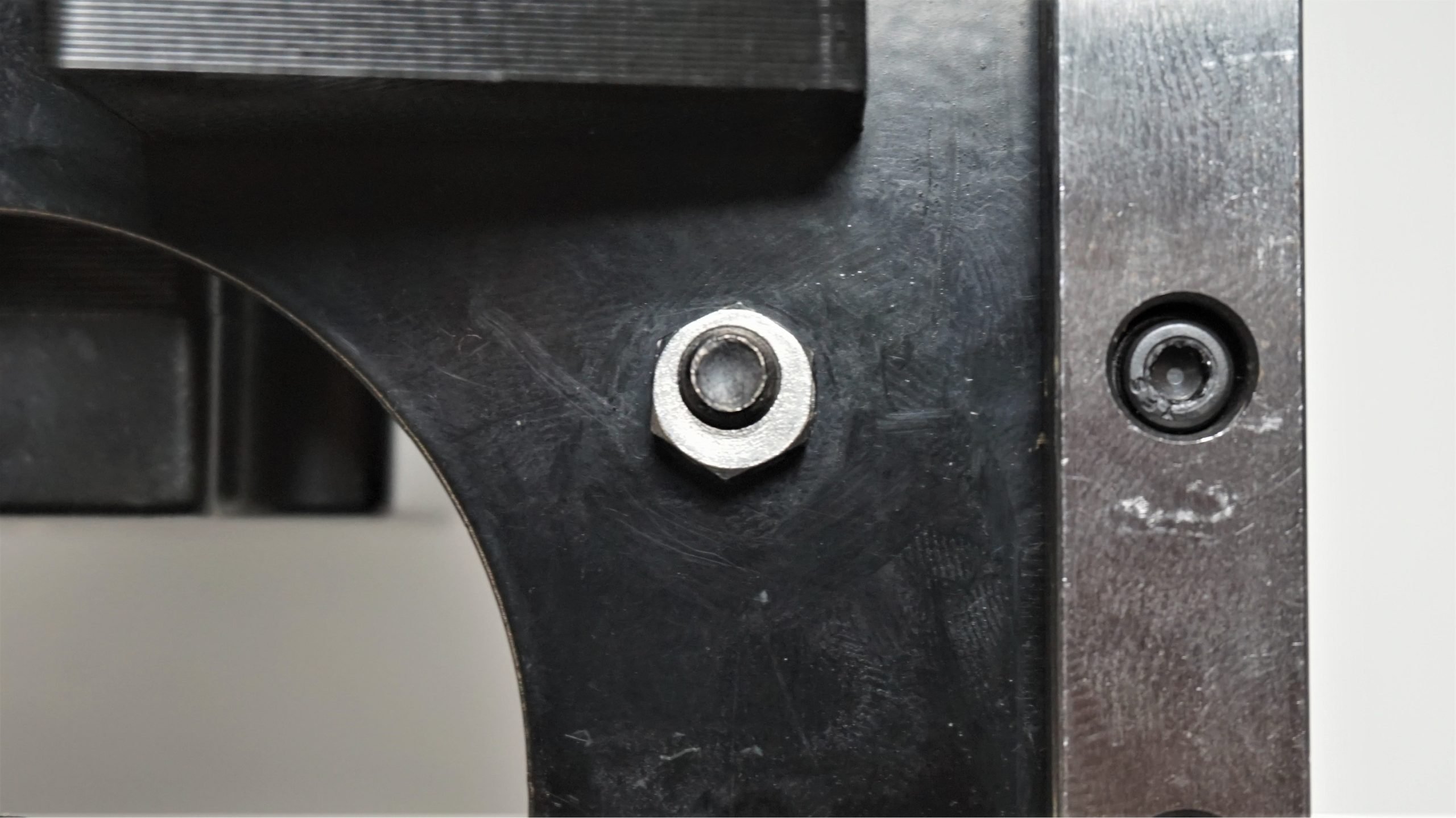
For the rear feet, we’ll also press-fit in eight M5 nylock nuts with the rounded side facing outwards. You should already have the bag of these medium-sized nuts open from earlier in the assembly.

Now, we’ll attach the two remaining motors to the rear feet. Install the coupler onto the motor first, followed by the long bolts and spacers that were used for the X-axis motor assembly.


Move this over to the back of one of the rear plastic feet, orienting the motors white connector or cable bundle towards the flat base of the foot (pictured). Using a size 4 Allen key, you’ll be able to bolt the motor in place. Repeat the process for the other foot.

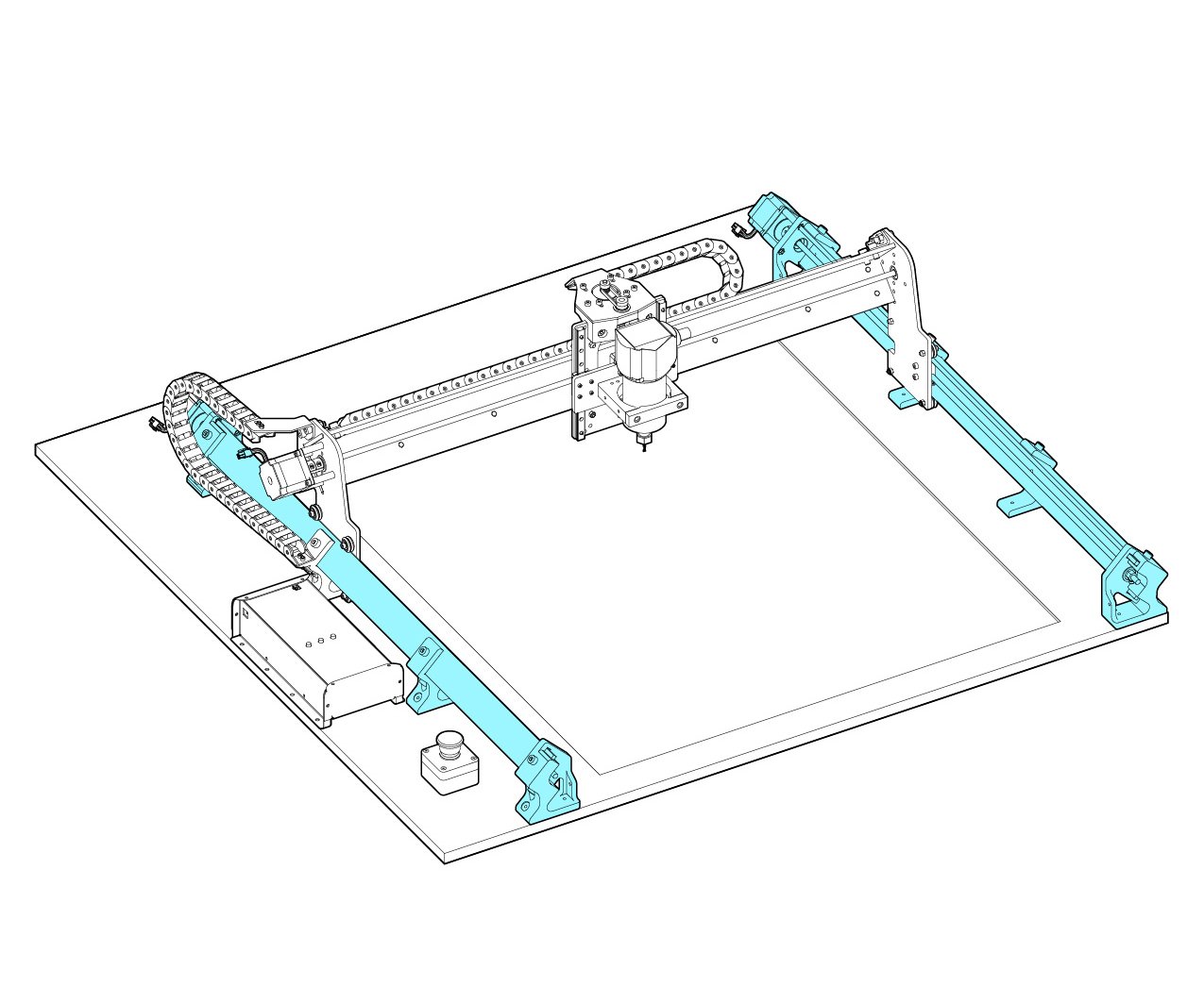
Completing the Y-axis
The 30×30 LongMill comes with 1000mm long rails for the Y-axis, meanwhile the 12×12 and 12×30 models have 500mm long rails. These will be the last two remaining aluminum lengths in the kit, distinguishable by their 2″ width compared to the 3″ width of the X-axis rail.
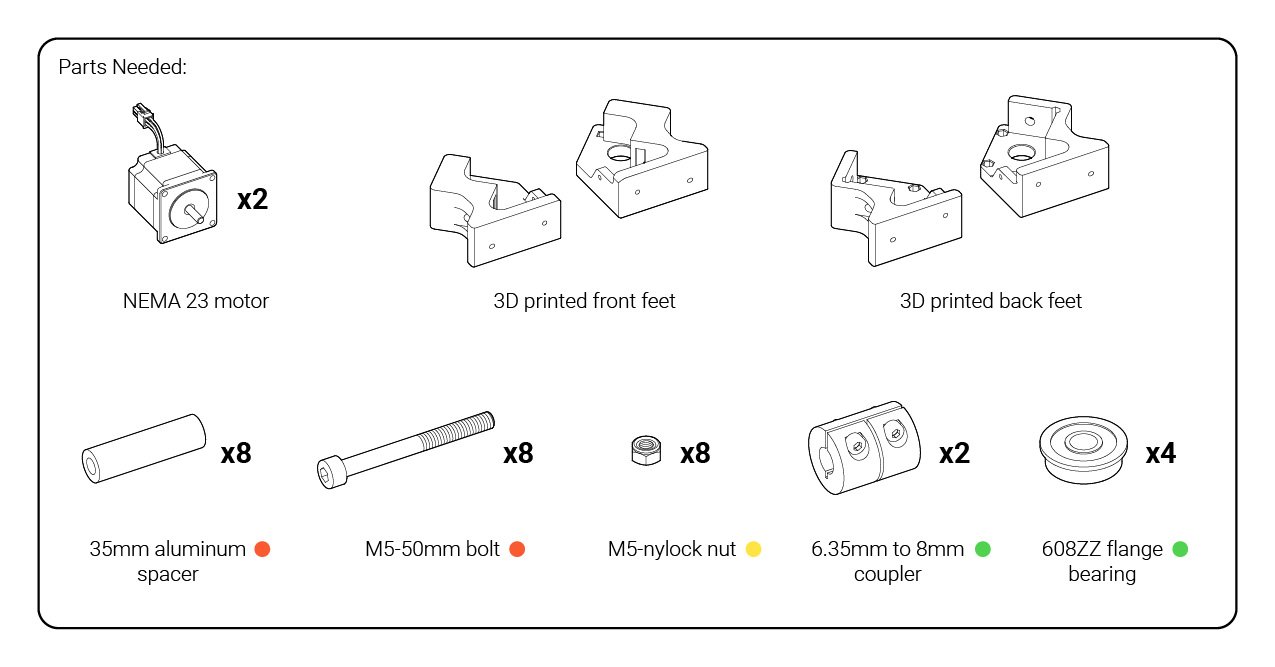
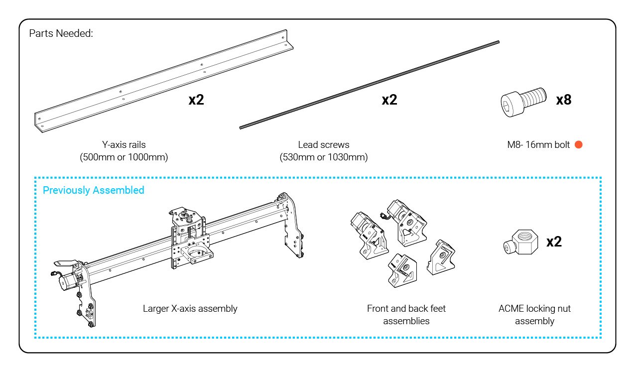
We will be doing the assembly for the 30×30 here, but the assembly for all three versions is very similar. Start by grabbing the two Y-axis rails, the feet assemblies from the last step, and the bag of the largest, short bolts.

Secure the rear left and right feet assemblies (pictured) to one end of each rail. These can be secured using two of the short M8 bolts per foot assembly using a size 6 Allen key; the rails should be a mirror of each other.
These rails need to now slide onto the larger X-axis rail assembly that you have set aside. To prepare for this, flip the X-axis assembly onto its front so that the router mount is contacting the ground; be sure that it’s stable in this position.
You should also check the current state of the eccentric nuts on both Y-gantries. Just like when you checked them on the XZ-axis gantry, they should be in their outer-most position so that there’s enough space between the wheels for the rail to fit.
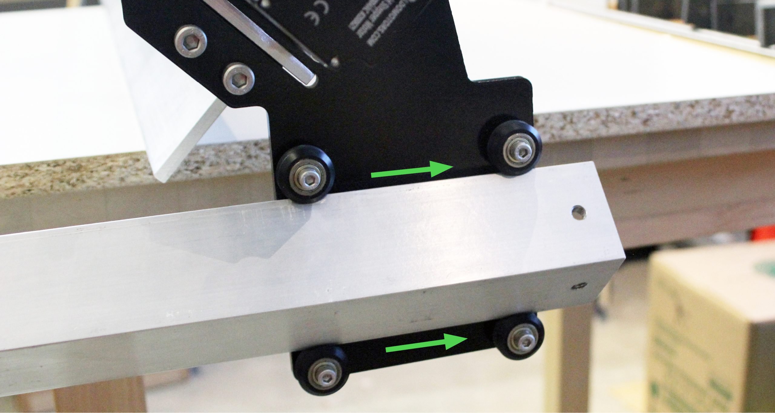
Now slide one rail onto the wheels of each of the Y-gantries from the back (pictured). Make sure that the flat side of the feet is pointing away from you so that, when completed, the machine is able to sit on the bottoms of the feet.
Leave this sitting for a second while you collect the two front feet assemblies and four more M8-16 bolts (found in the orange bag) in preparation for this next step. You’ll have to make a combined motion where you tilt the X-axis rail assembly backwards while you finish sliding the Y-axis rails all the way on. Be very careful while doing this. It’s possible to lose control of the heavy components and have them fall away from you and become damaged.
Once you’ve slid the rails all the way on to the X-axis rail assembly, use the two front foot assemblies we collected earlier. Sliding them into place and mounting them to the front of each rail on their respective sides with two bolts each and a size 6 Allen key will help to keep the large assembly more stable.
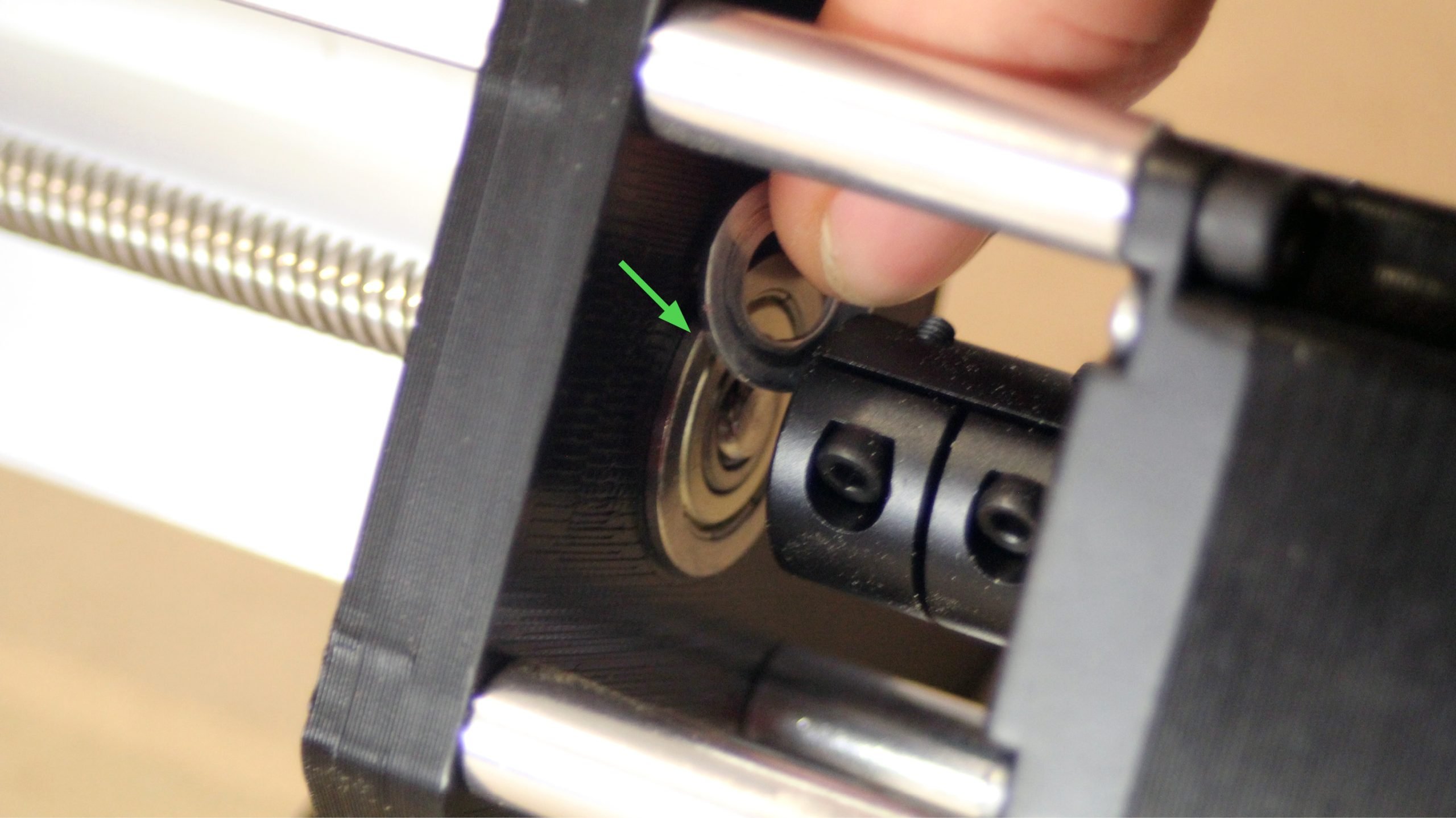
Next, thread the lead screws into place. It will go through the bearing on the front foot, threaded through the nut block on the Y-gantry, and through the bearing on the back foot. If you move the gantry to the back of the machine when doing this (pictured) it’ll require less time to thread it through.

Just like for the X-axis assembly, put a washer between the coupler and the bearing on the motor-side of the back feet. If the lead screw is getting a bit stuck on the bearing or coupler, you may have to do some wiggling or lightly tap it into position with a mallet from the other end.
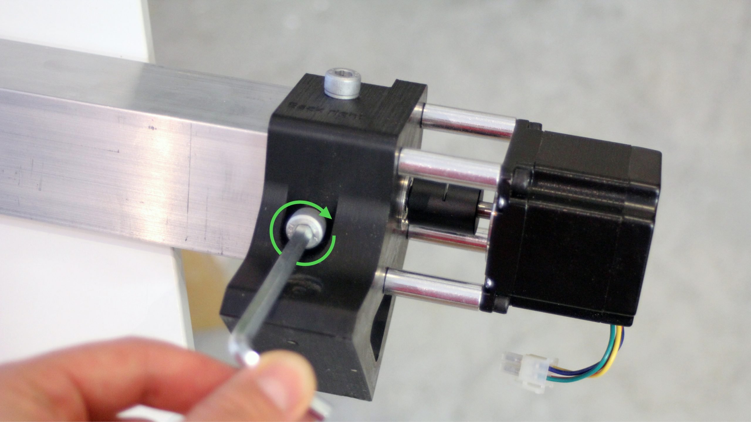
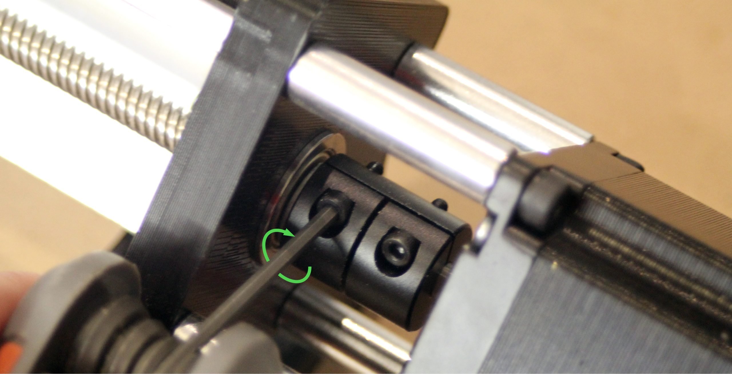
Tighten everything down by pushing the lead screw all the way towards the motor shaft while pushing the coupler all the way towards the bearing, then tightening down the coupler set screw on the side of the lead screw (pictured). Do this on both sides.
Back at the front of the machine, the last two of the ACME locking nut assemblies are going to be used to constrain the lead screws on the Y-axis. Screw these on and tighten their set screws. These share the same purpose with the locking nuts on the X and Z-axes, where the combination of the nut on one side and the coupler on the other side keeps the lead screws from moving side-to-side; so it’s a good idea to check that everything is secure by gently pushing and pulling on the lead screw to check for any looseness.
Do this on both sides. Adjust the couplers and tighten the ACME lock nut more if you feel any play, since you should be able to rotate the lead screw freely but not feel any side-to-side looseness.

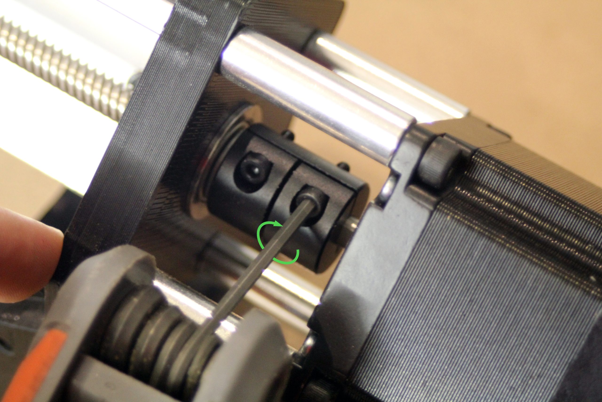
After making sure there is no play in the lead screw, go back to the motor side and tighten the coupler set screw onto the motor shaft on Y-axis motors.
Attaching the middle feet
12x12 and 12x30
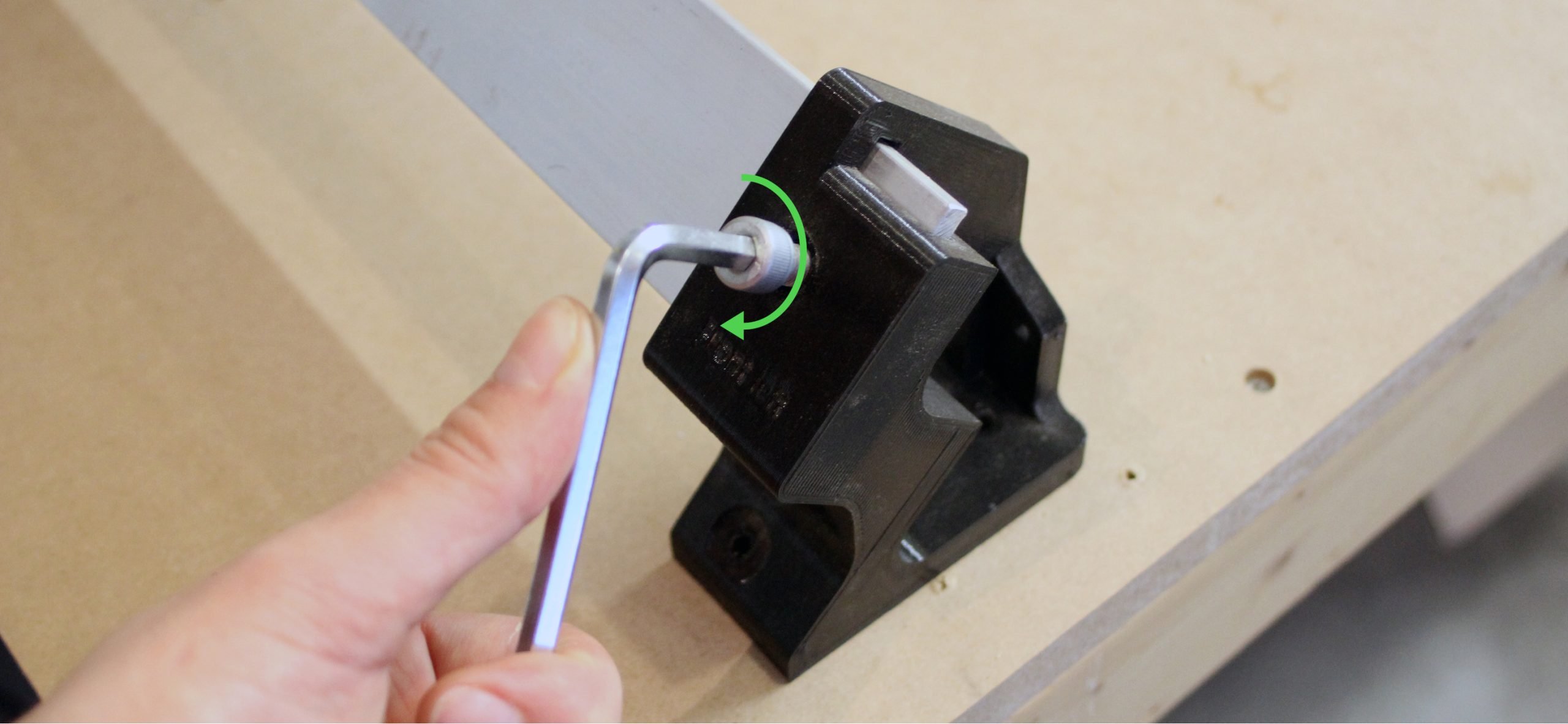
The last part to add is the middle foot. It looks exactly like the back feet but excludes the backing (pictured). There are two of these parts that look very similar but the other one has another mounting point that juts out; this one will be used later in the assembly.
Attach the middle foot onto the right-side rail using two of the same short M8 bolts that you used to attach the other feet and a size 6 Allen key. It’s best to twist the bolts into place by hand first, then finish tightening them snug with the Allen key.

30x30
The last pieces to add are the middle feet. They look exactly like the back feet but exclude the backing. There are three of them and a fourth one that looks very similar but has another mounting point that juts out; this one will be used later in the assembly.
Attach the middle feet in the positions indicated in the below picture. Just like the other feet, they can be attached using two of the short M8 bolts and a size 6 Allen key. It’s best to twist the bolts into place by hand first, then finish tightening them snug with the Allen key.
