
Congratulations on getting your LongMill MK2 48″ extension kit! In just a few steps, you’ll soon have a much larger CNC with 56% more cutting area than before, as well as the ability to pass full width 4′ sheets of material through.
The assembly instructions are available both online and as a PDF that you can download by clicking on the link below:
 MK2 48″ Extension Kit Manual |
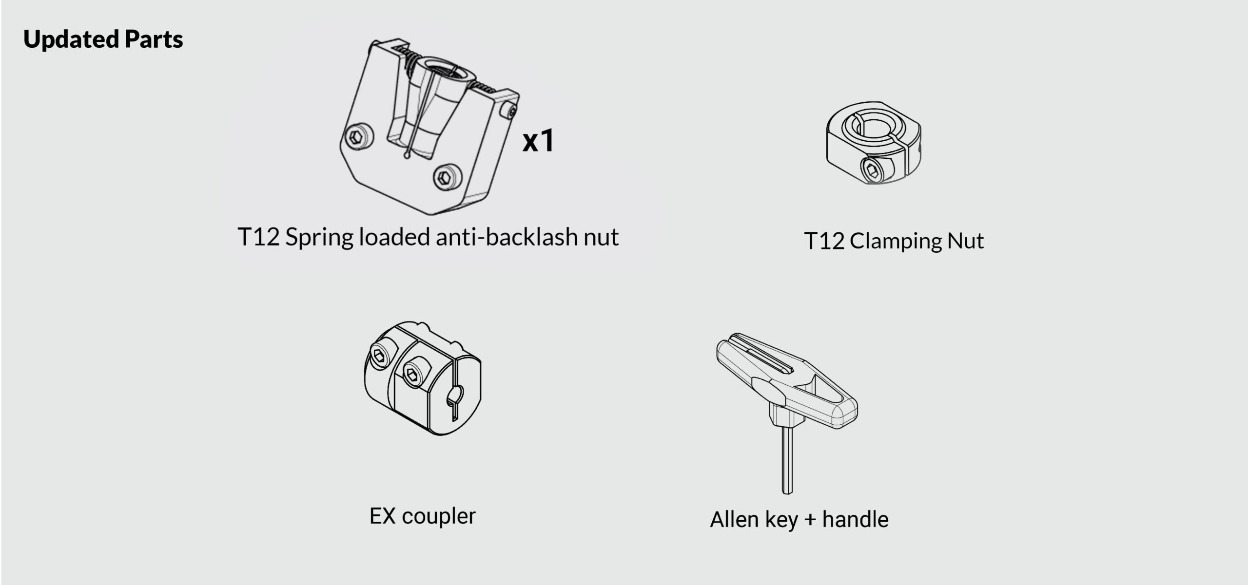
Updated Parts
We have updated several of the parts you will use in upgrading to the 48″. They will all easily and seamlessly replace the previous ones. To see the most updated version of our 48″ assembly PDF or online manual, you can visit our MK2.5 assembly section.
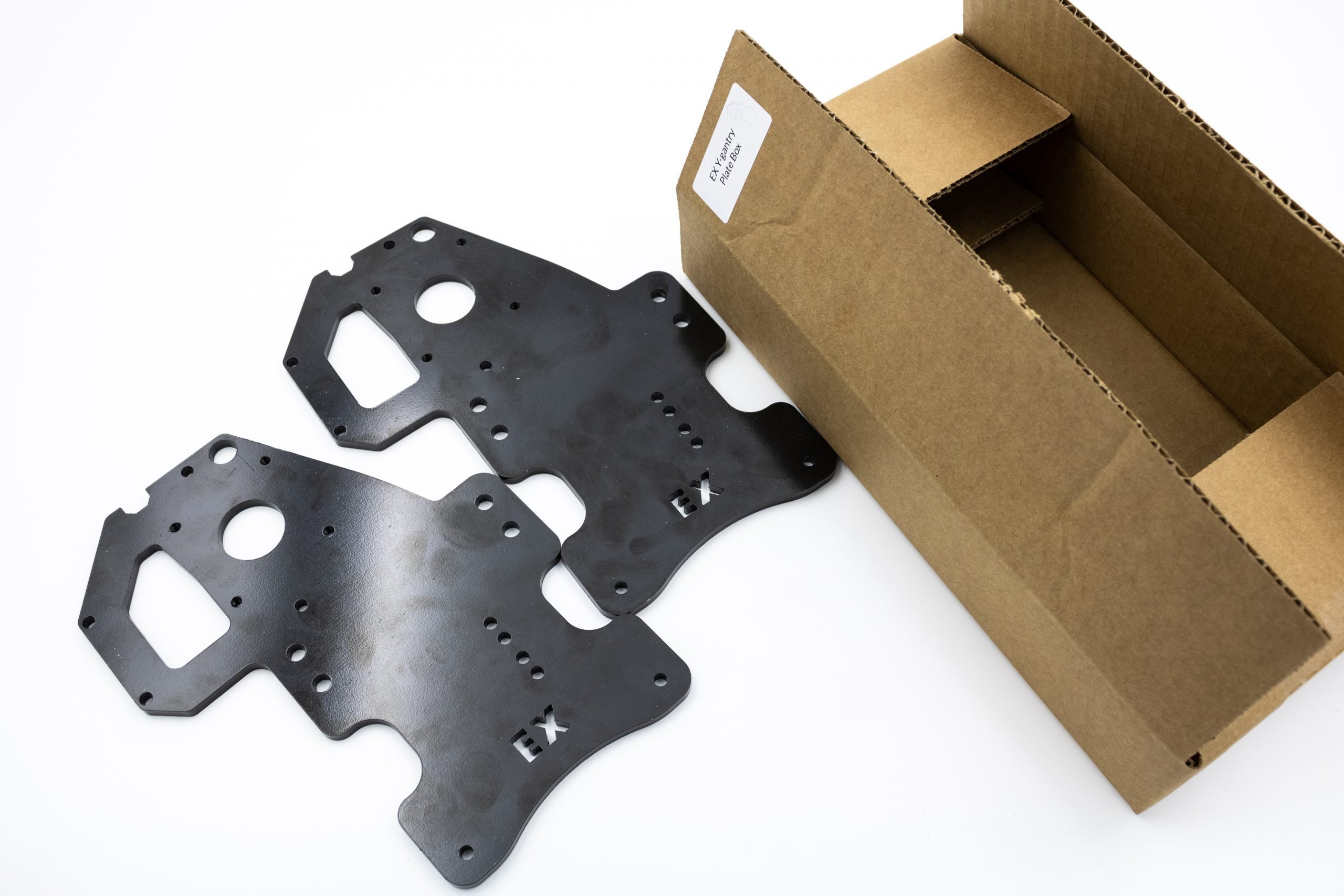
48″ X-axis rail box unpacking
Inside the 48″ X-axis rail box, you’ll find the X-axis rail packaged with 5 boxes.
The ‘EX hardware box’ contains various hardware that is used when assembling the extension kit, the EX drag chain & cable box contains a longer 1400mm drag chain and various cables, the Y-axis gantry plates box contains the two EX Y-gantry plates, and the MK2 EX hardware box contains some small parts specific to this extension kit.
The last box serves to fill empty space inside the rail box and better protect the X-axis rail during shipping. You’ll want to unpack all hardware from these boxes and set this aside for whenever it is called during assembly.


Tools you’ll need
You’ll need these tools on hand for assembly. Most people will have these in their shop:
- Metric Allen keys (we provide)
- Metric wrenches, metric socket set, or adjustable wrenches.
- A small flat head screwdriver
We don’t recommend you use an impact driver for assembly except when mounting the machine because you won’t save much time and some assemblies are prone to damage if they’re overtightened
Missing/broken parts?
Don’t sweat it – your kit has spares and redundancy included. If a part is lost or isn’t going together how you expect, no worries; just check through the bags and you’ll likely find what you need to continue assembly. Expect some bolts left over at the end and feel free to set these aside for future machine maintenance.
We supply extra parts so that:
- If a part doesn’t work properly the extra one can be used instead
- If you lose something (especially small things) you don’t have to search the floor
- We reduce the chance of packing too few on our end
If a part is missing completely, check that you’re looking for the right thing and ensure you look through all the packaging you received with your extension kit. Some parts and add-ons such as the t-tracks ship in a separate package if they can’t fit into the same box.
If a part arrives broken and doesn’t have a spare, the LongMill extension kit’s warranty covers replacement parts and we’ll even be happy to help you out if you break it yourself. Just shoot us a message here (https://sienci.com/contact-us/) and see if there are any other areas of assembly you can continue with in the meantime. We’ll get back to you as soon as we can.
Assembly tips
- Take breaks when needed
The assembly process can take a few to several hours. Pace yourself and enjoy the process. - Read the instructions
Many issues during assembly can be solved by re-examining the instructions. Check that you didn’t skip a page and that you completed the previous step correctly. Some steps are hard to explain and some parts have names that are hard to remember so looking at the pictures more closely can also help you to better understand what needs to be done. Reading is encouraged if you’d like more detail on where to locate the part, what function it serves on the machine, and other elaborative information. Our assembly videos can’t be updated as often as the online or PDF instructions so if packaging or parts change the written manual will always be able to clarify these changes. - Remember the language
This manual contains some technical language as well as a distinct visual language. Keeping these in mind will make the assembly easier for you to understand and ensure that less mistakes happen.
Description Image • Section title pages: show the part of the machine you’ll be working on next 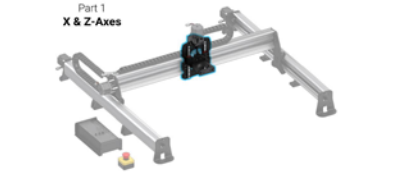
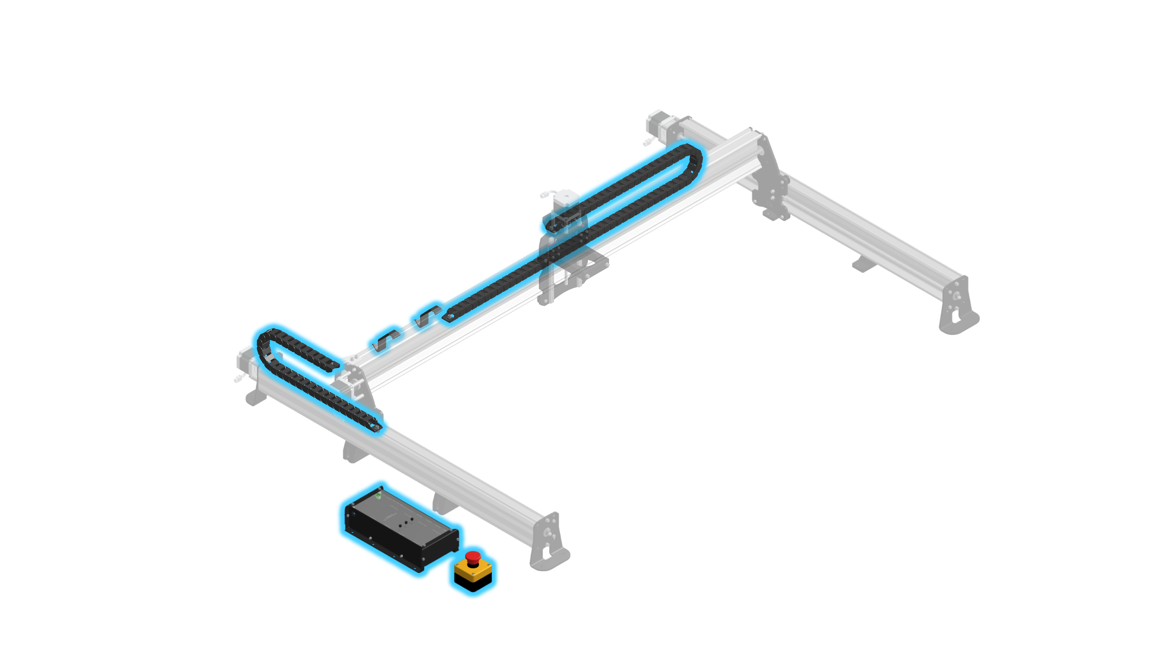
• Transparent parts: outlined in blue with a blue arrow path to show where the part starts and where it ends up 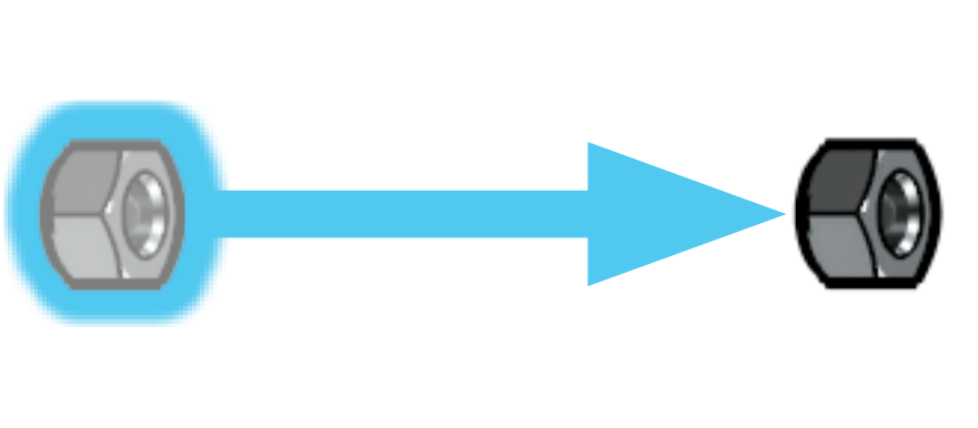
• Rotation arrows: come as either blue or red, blue indicating a loose placement of the part and red indicating a firm tightening required to fasten the part into place 
• Caution triangles: marks something that requires attention 
• Large green circles: provide a secondary view of the current step for added clarity 
• X, Y, and Z: during assembly if you see these capitalized letters used it’s because we refer to some parts by the axis they belong to. For reference, if you’re looking at the LongMill from the front, the X-axis is when the machine moves left/right (red), the Y-axis is towards/away from you (green), and the Z-axis is moving up/down from the tabletop (blue). 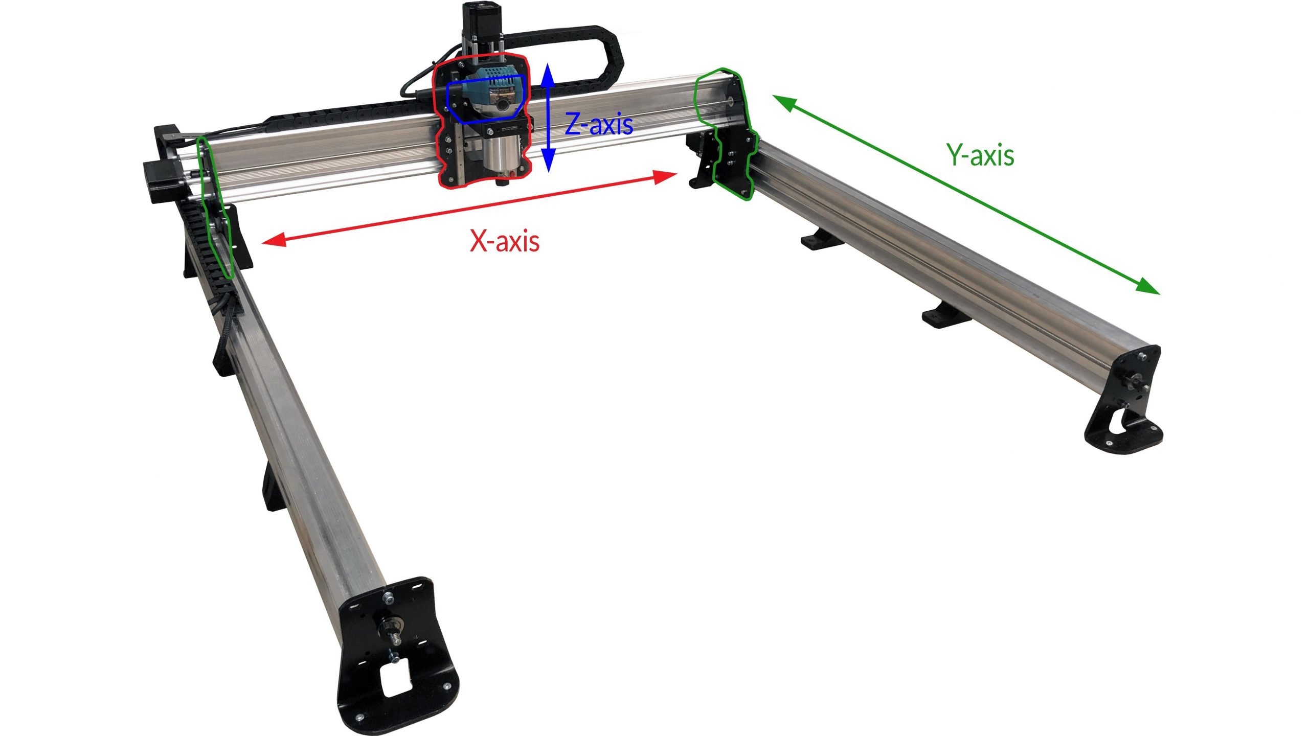
• 48″ EX symbol: always comes after a blurb of text to indicate that you’ll need to follow a few different steps outlined in the accompanying manual. If you aren’t assembling the 48×30 model of the LongMill MK2 you can ignore these 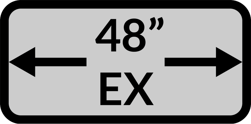
- Set aside a clean space for disassembled parts
Since installing this extension kit will require the removal of some parts, as well as the reusing of some, make sure you can set these parts aside without losing any or mixing anything up.This manual will specify which parts will and will not be reused for final assembly of the 48×30″ machine.
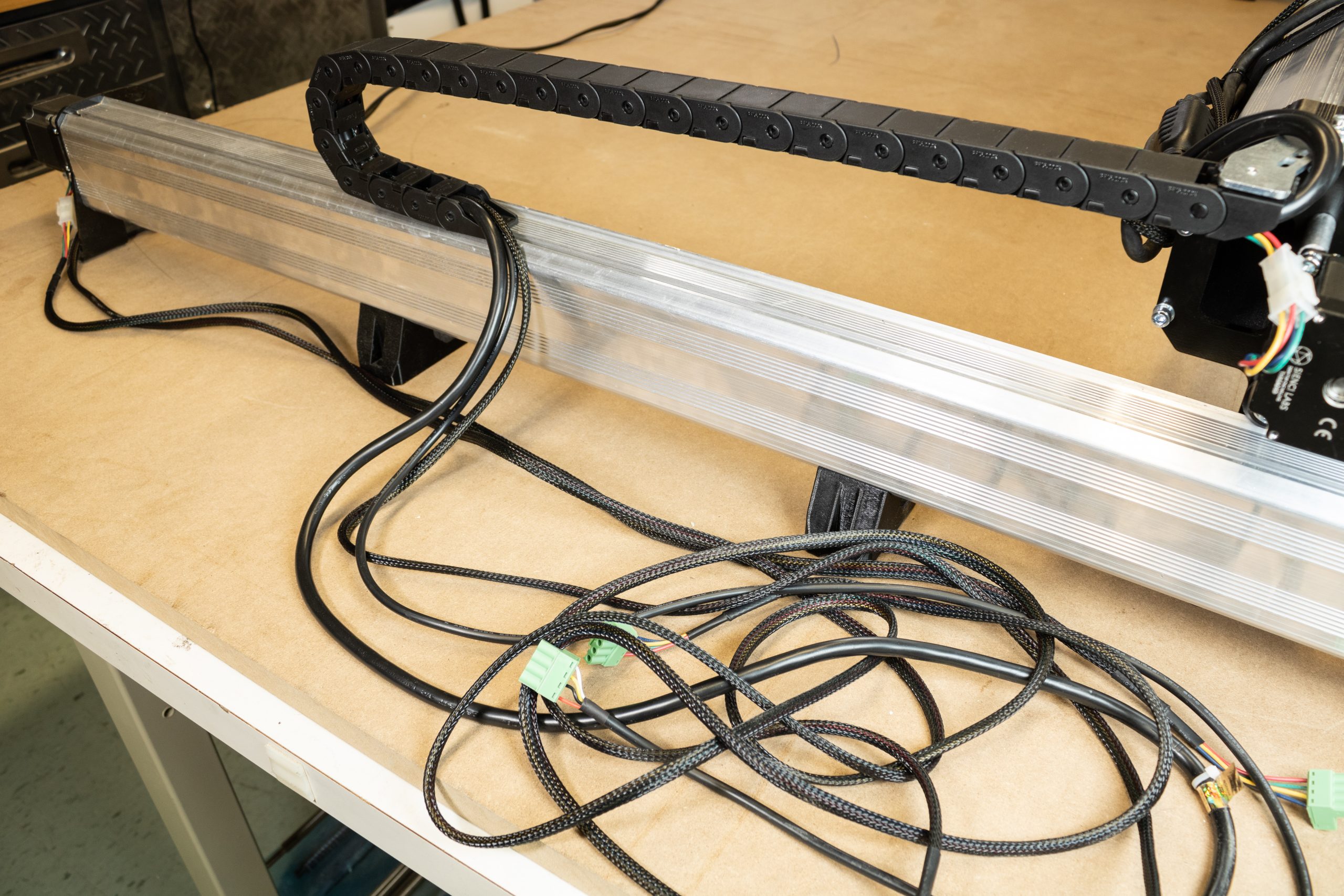
Drag chain and wiring disassembly
Disassembling the drag chains
On the Y-axis drag chain, start unclipping any of the clips securing the wires along the Y-axis. Detach the start and end links from this drag chain, then remove the drag chain entirely.
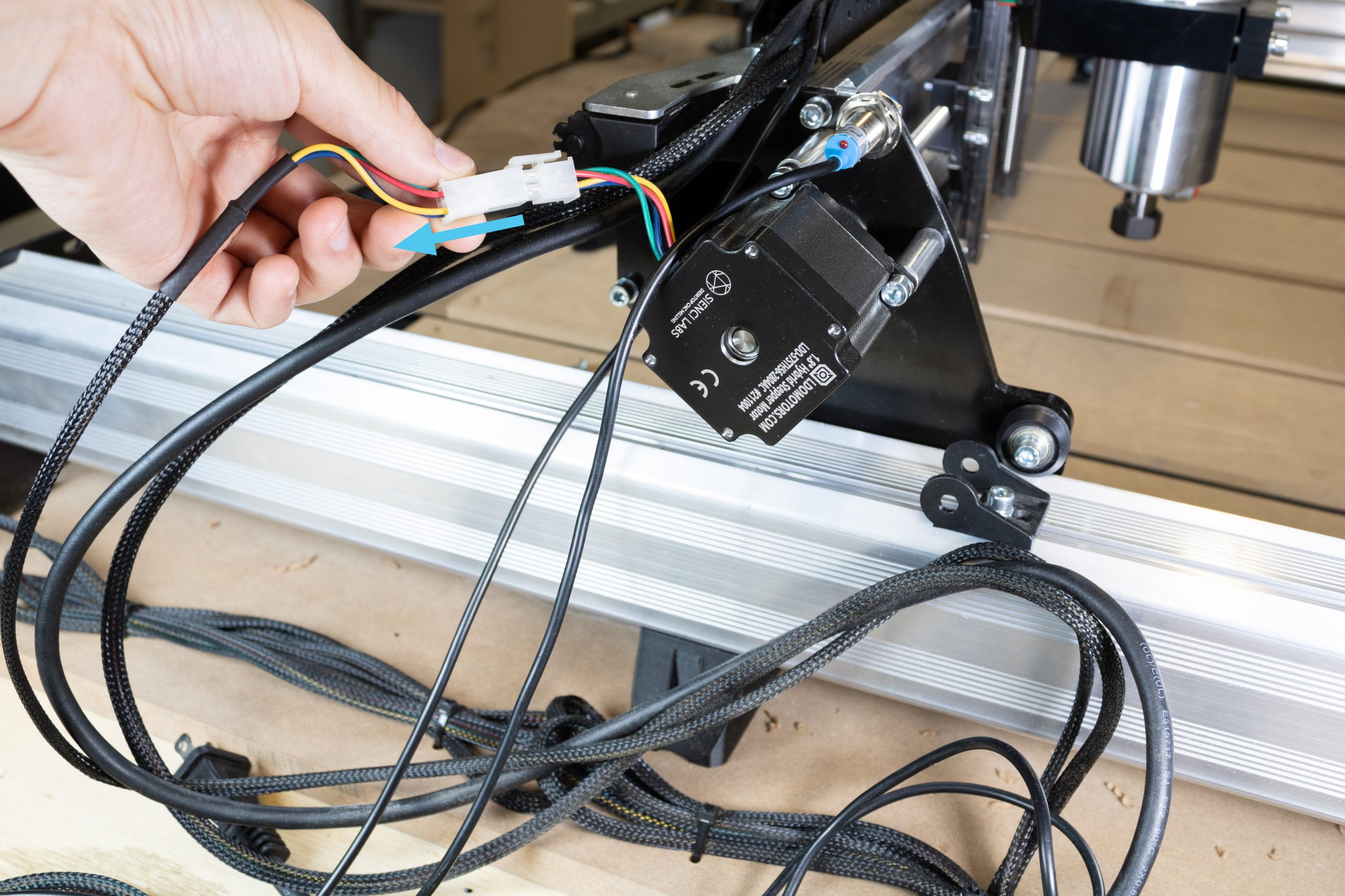
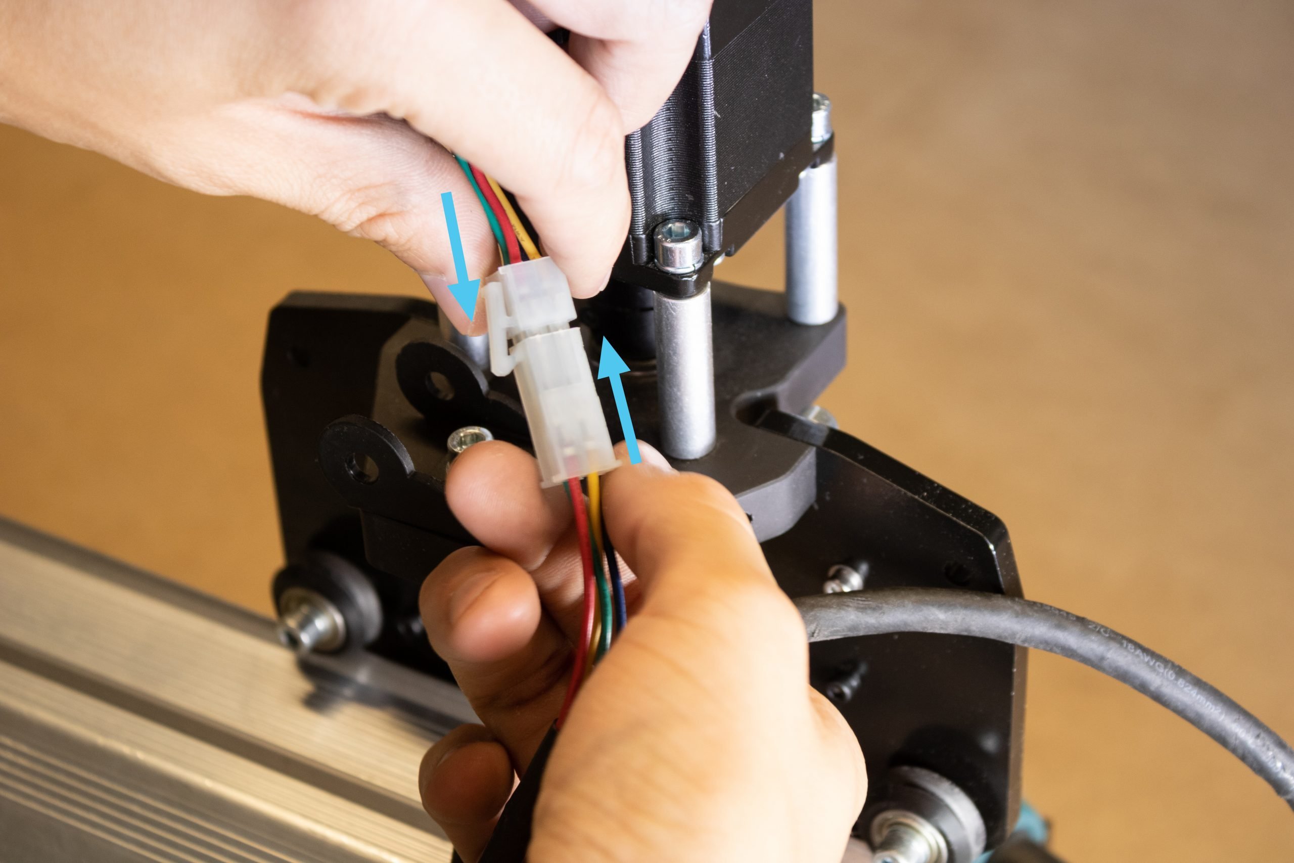
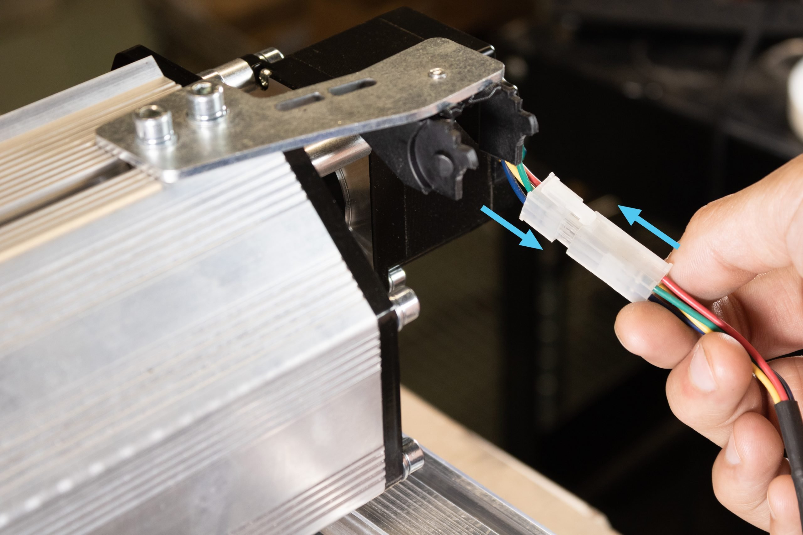
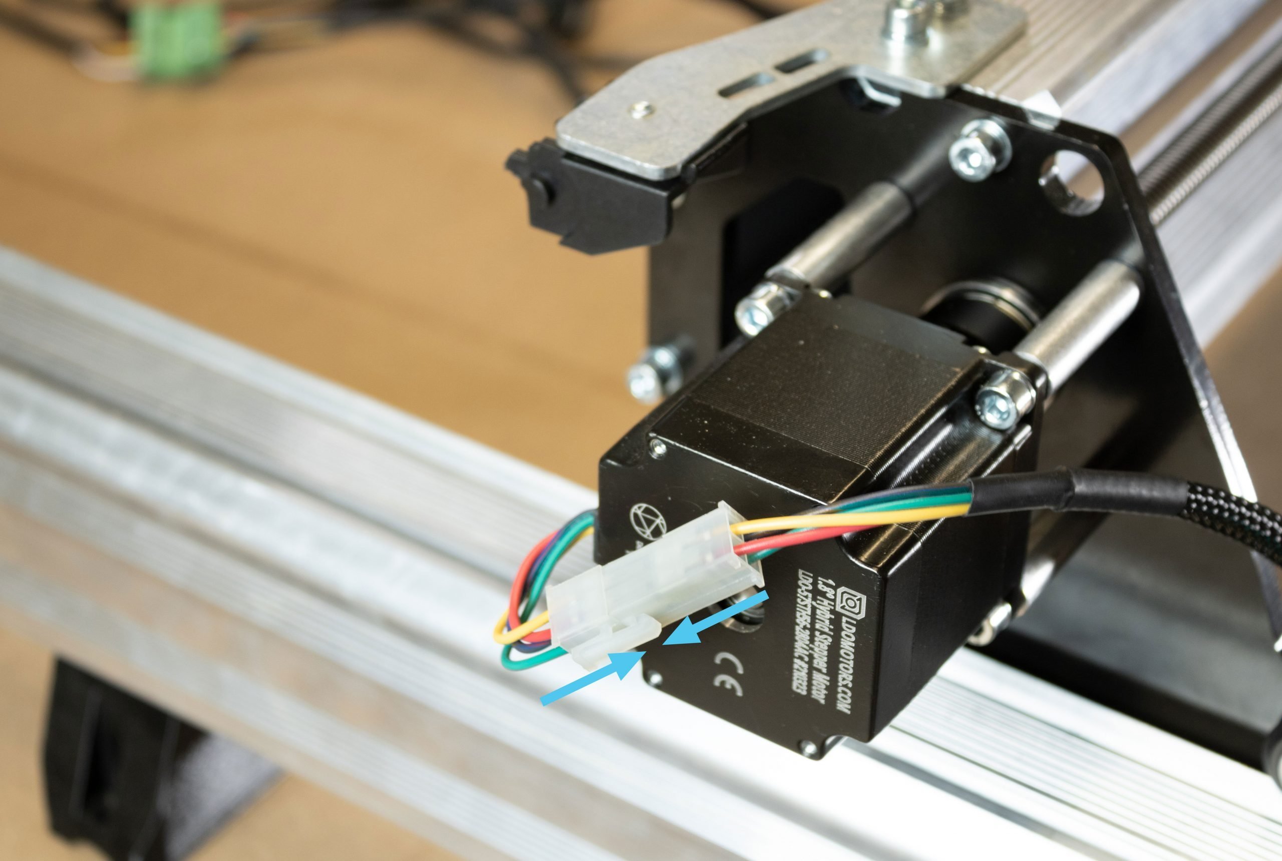
Disconnect the X-axis motor connector.
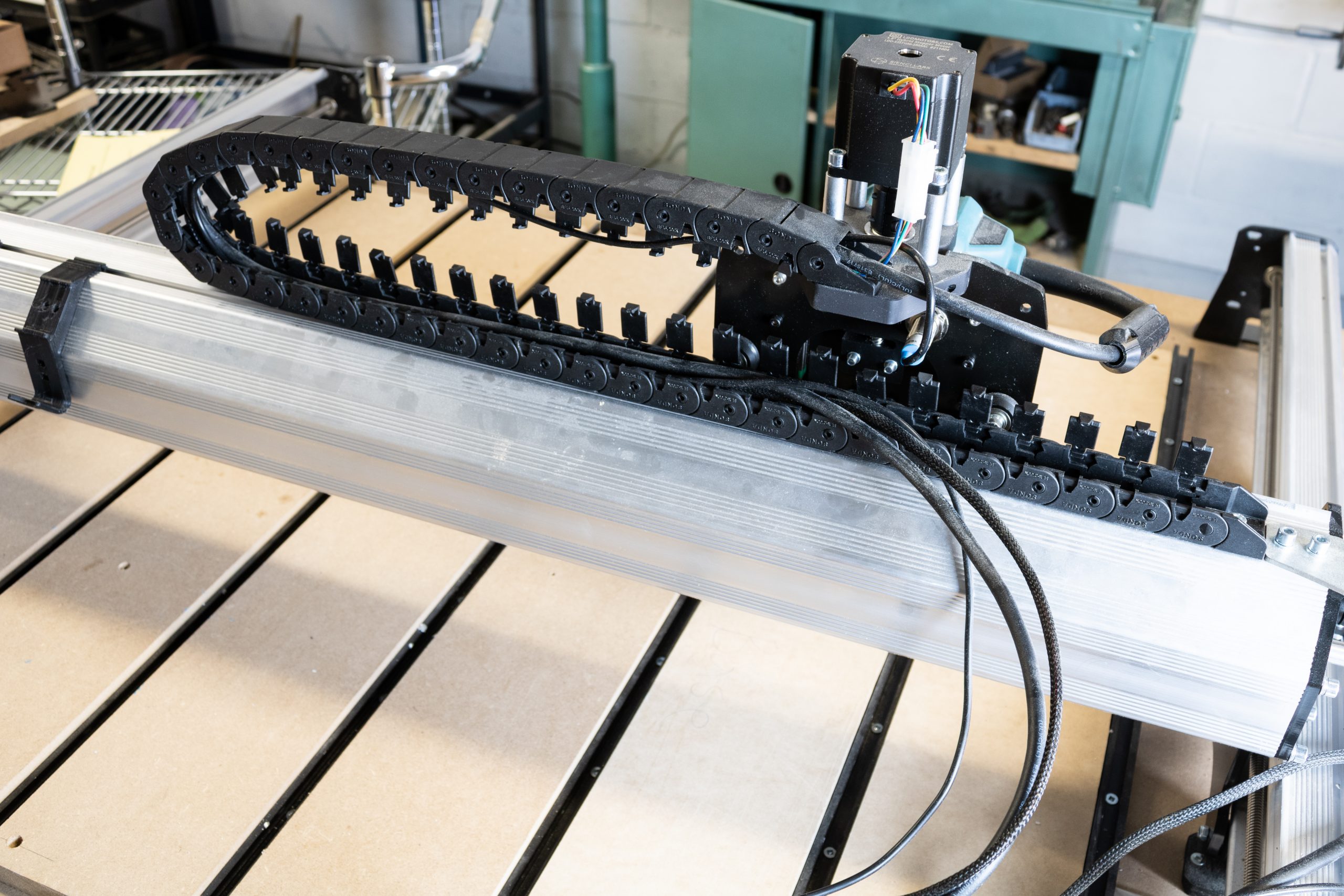
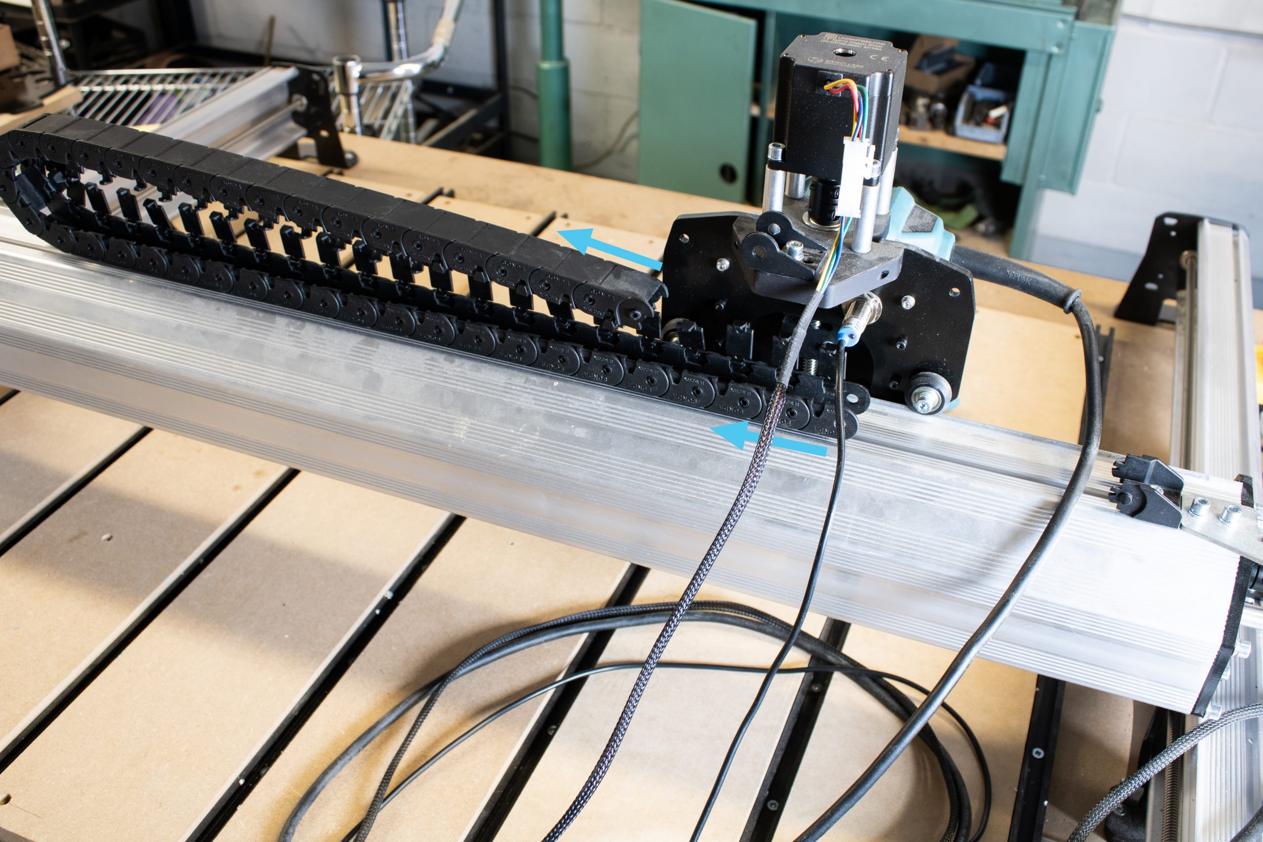
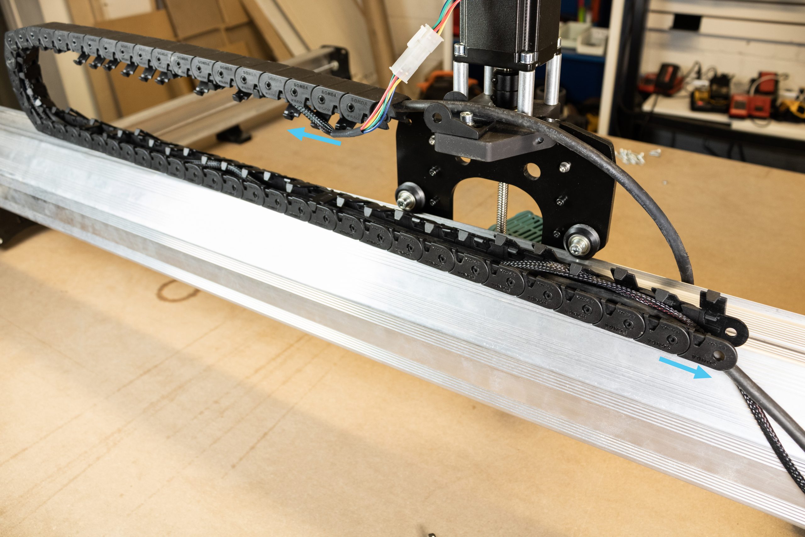
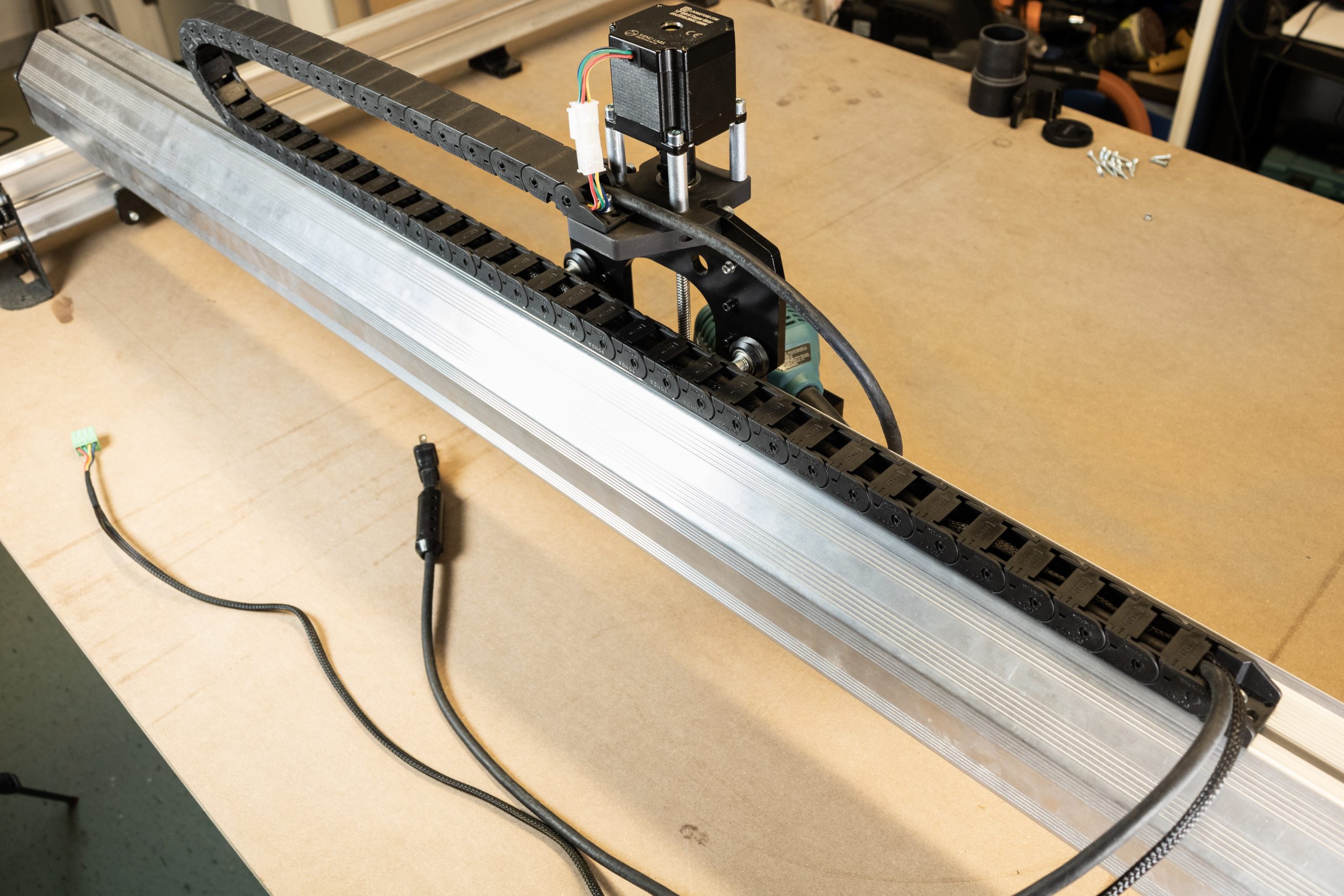
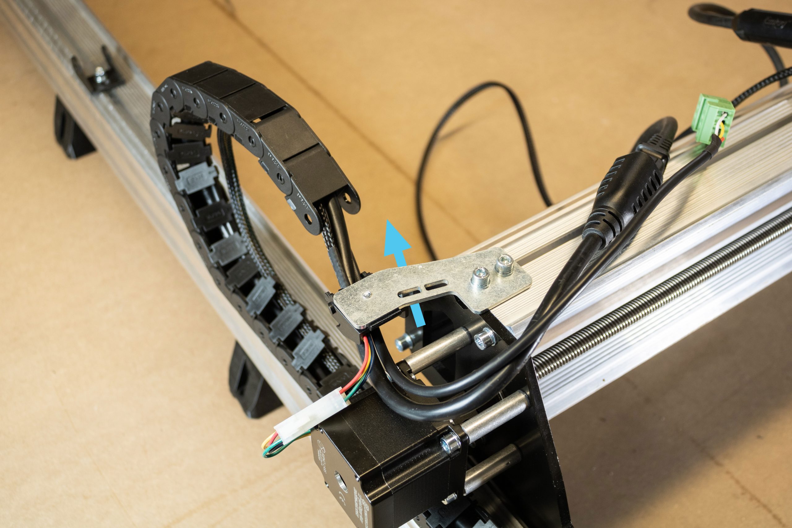
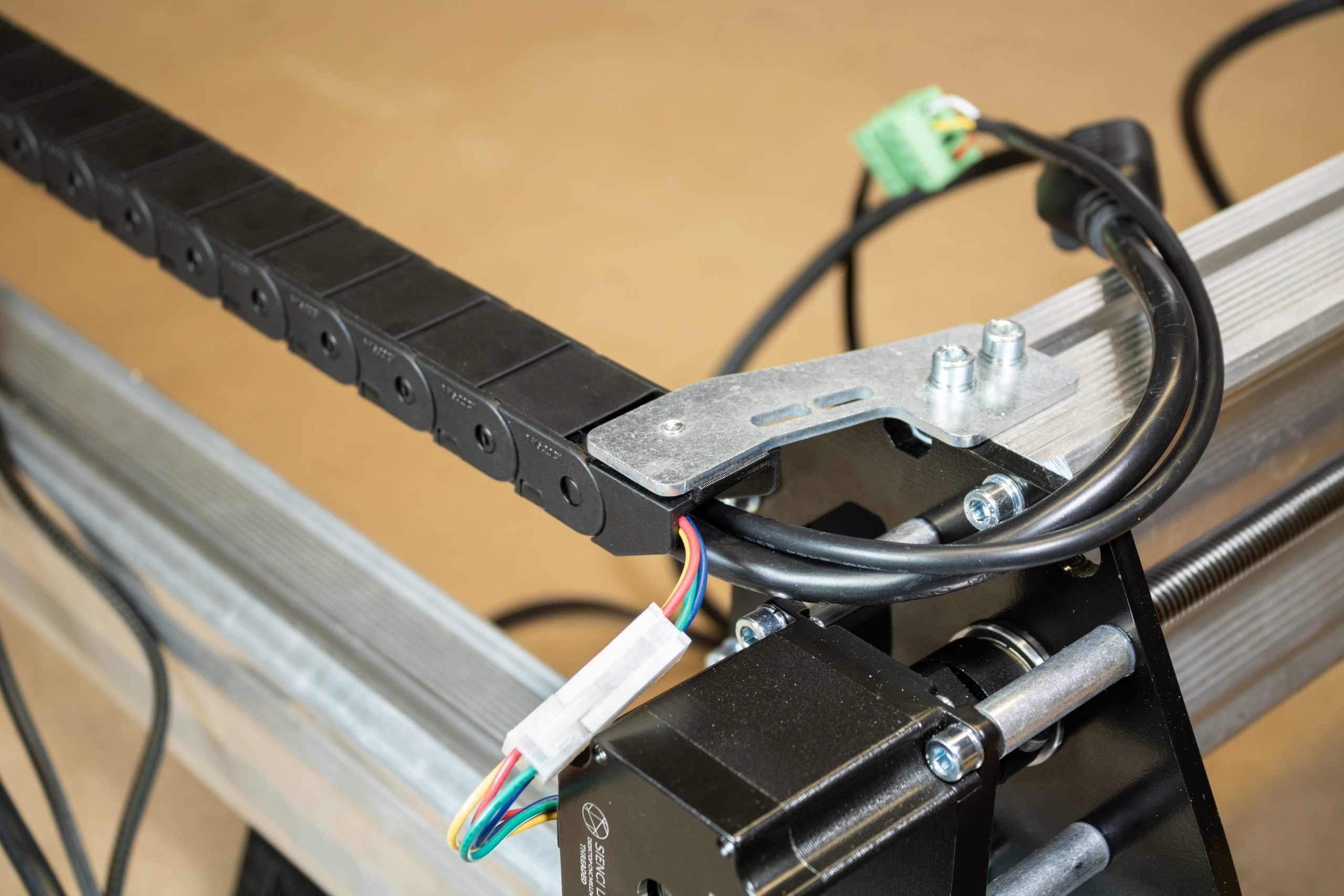
On the X-axis drag chain, unclip the clips securing the wires along the X-axis. Detach the start and end links from this drag chain, then remove the drag chain entirely.
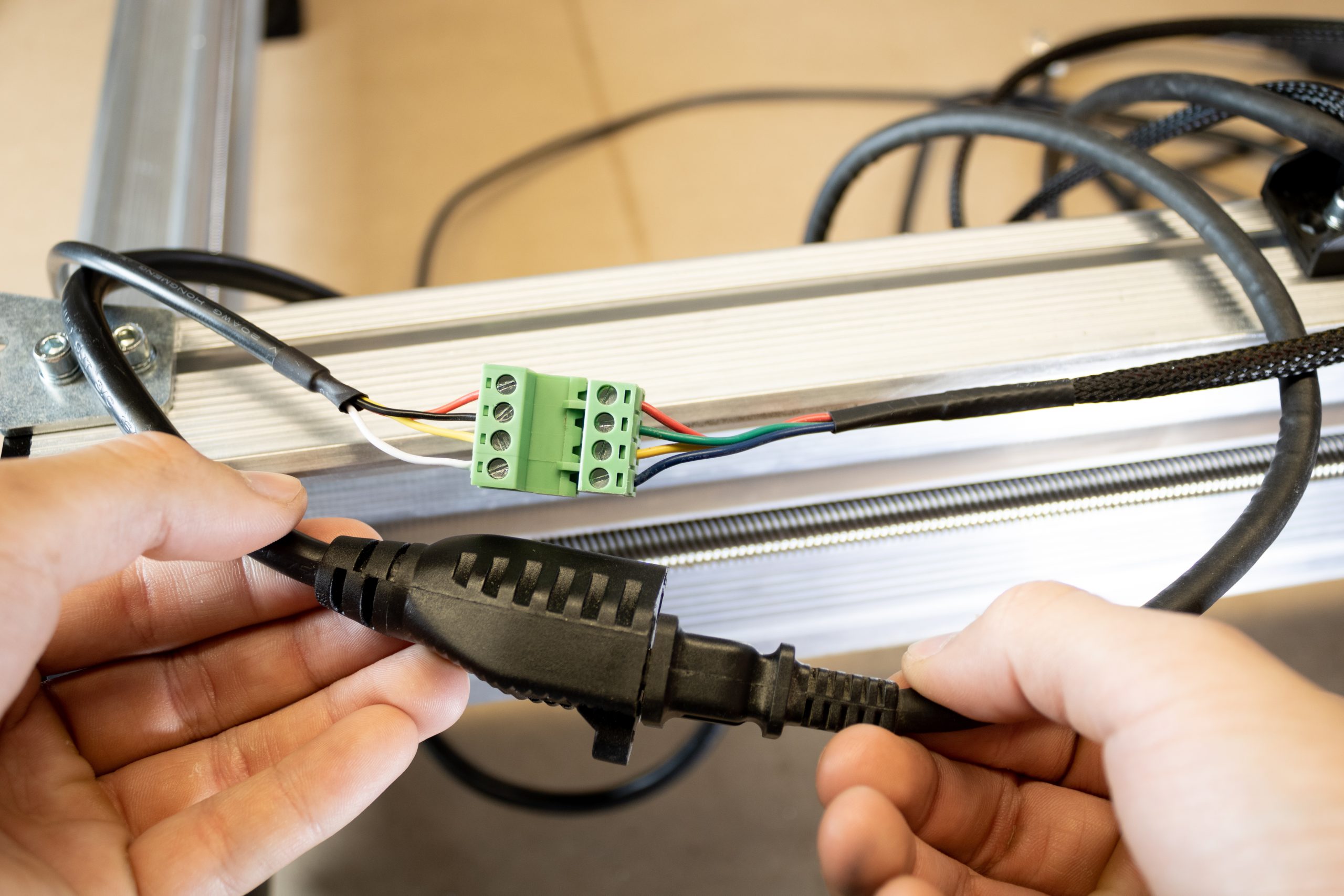
Disconnecting wiring
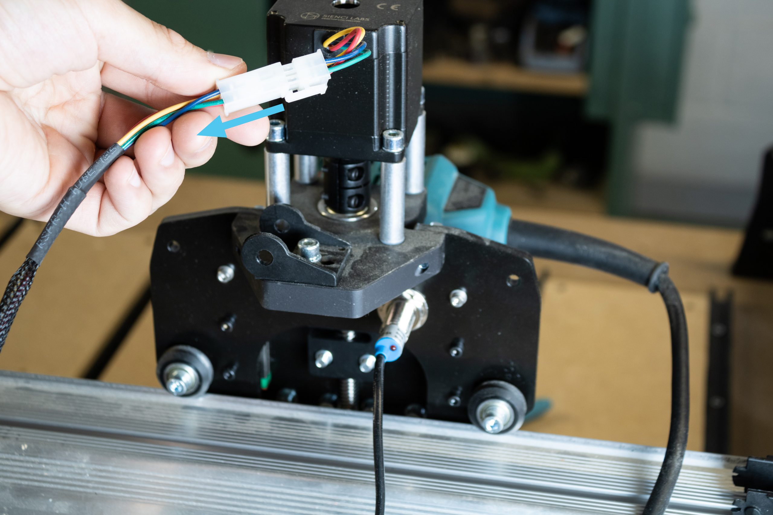
Disconnect the motor cables going to the Z-axis motor and X-axis motor. Disconnect and remove any other add-ons such as limit switches or laser if installed. Disconnect any of these cables from your control box as well.
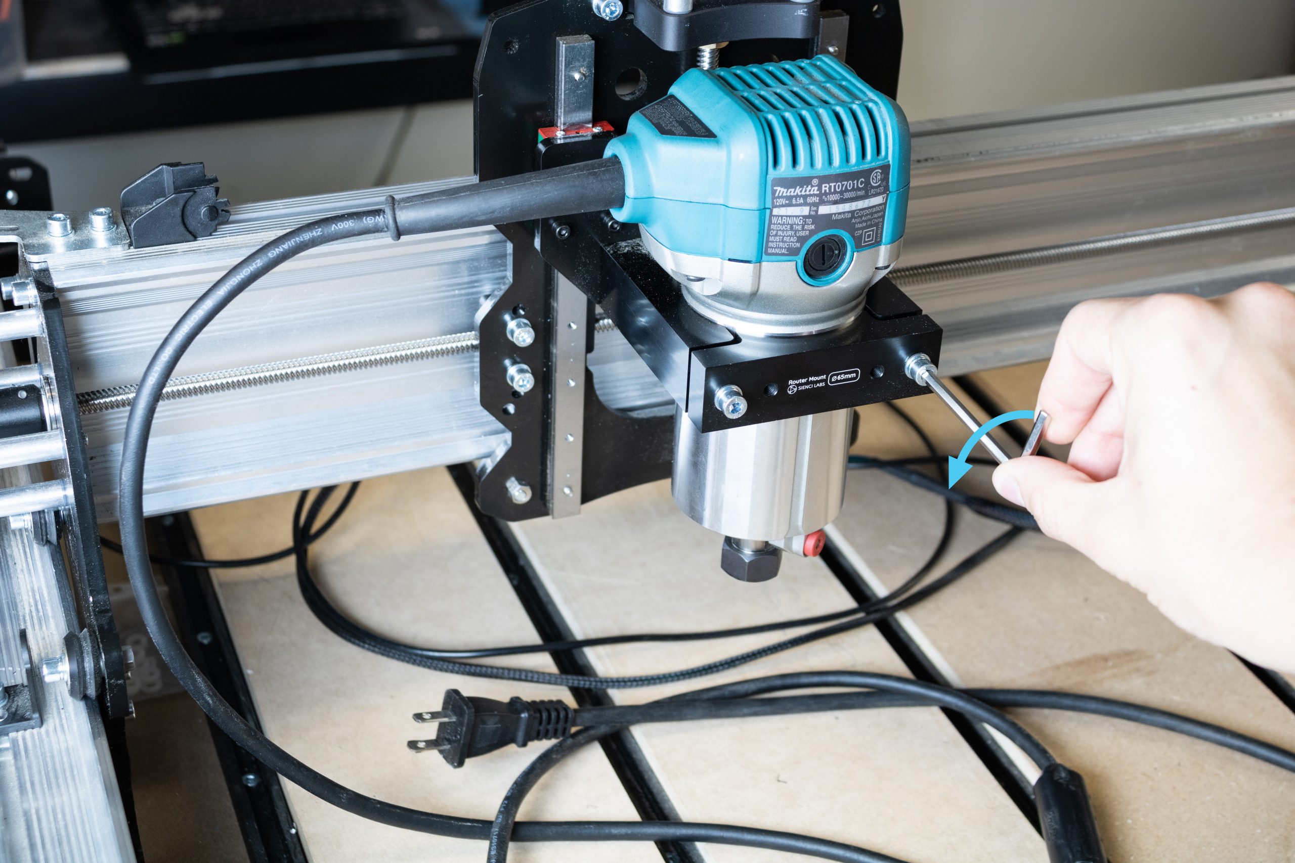
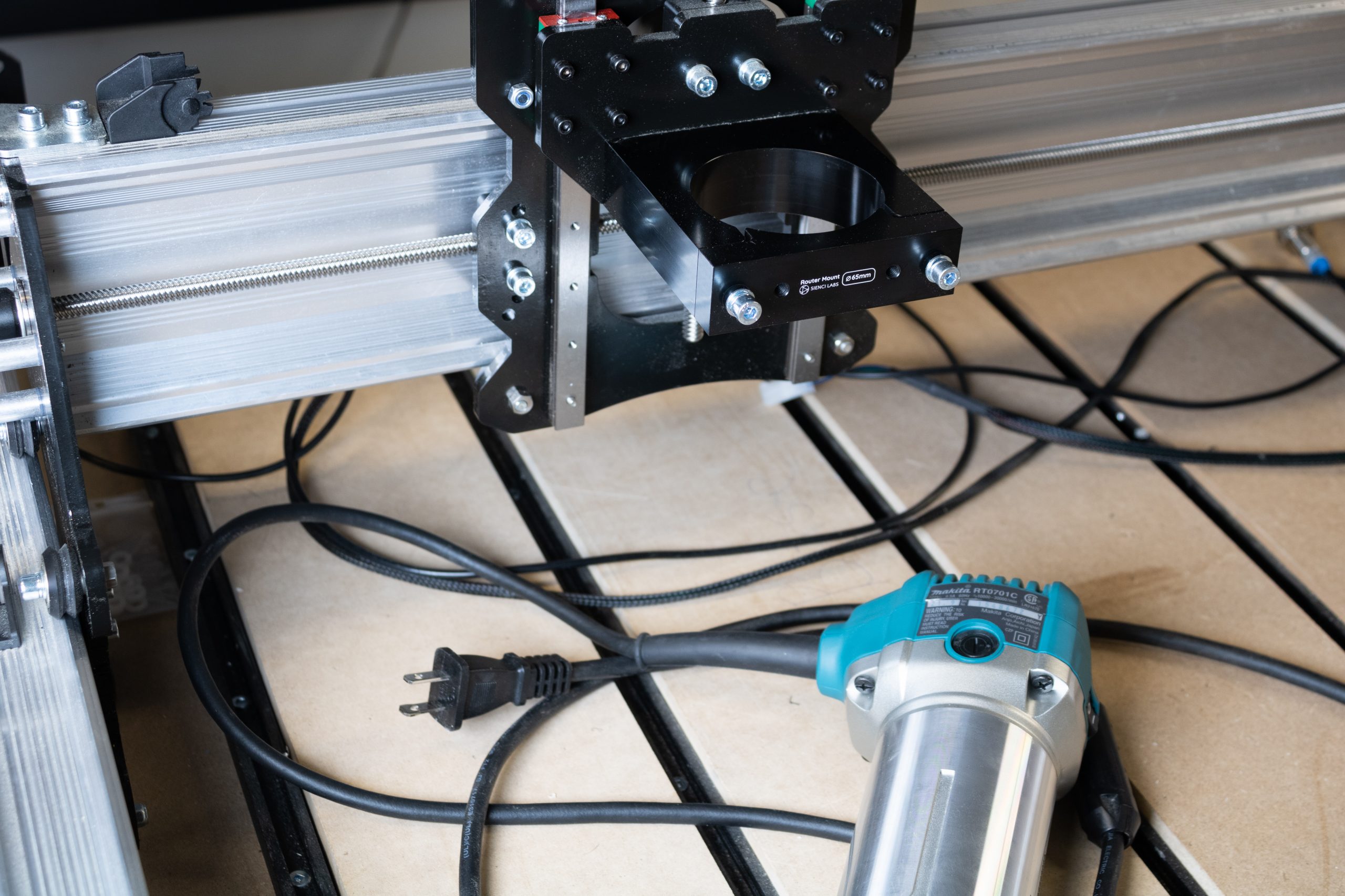
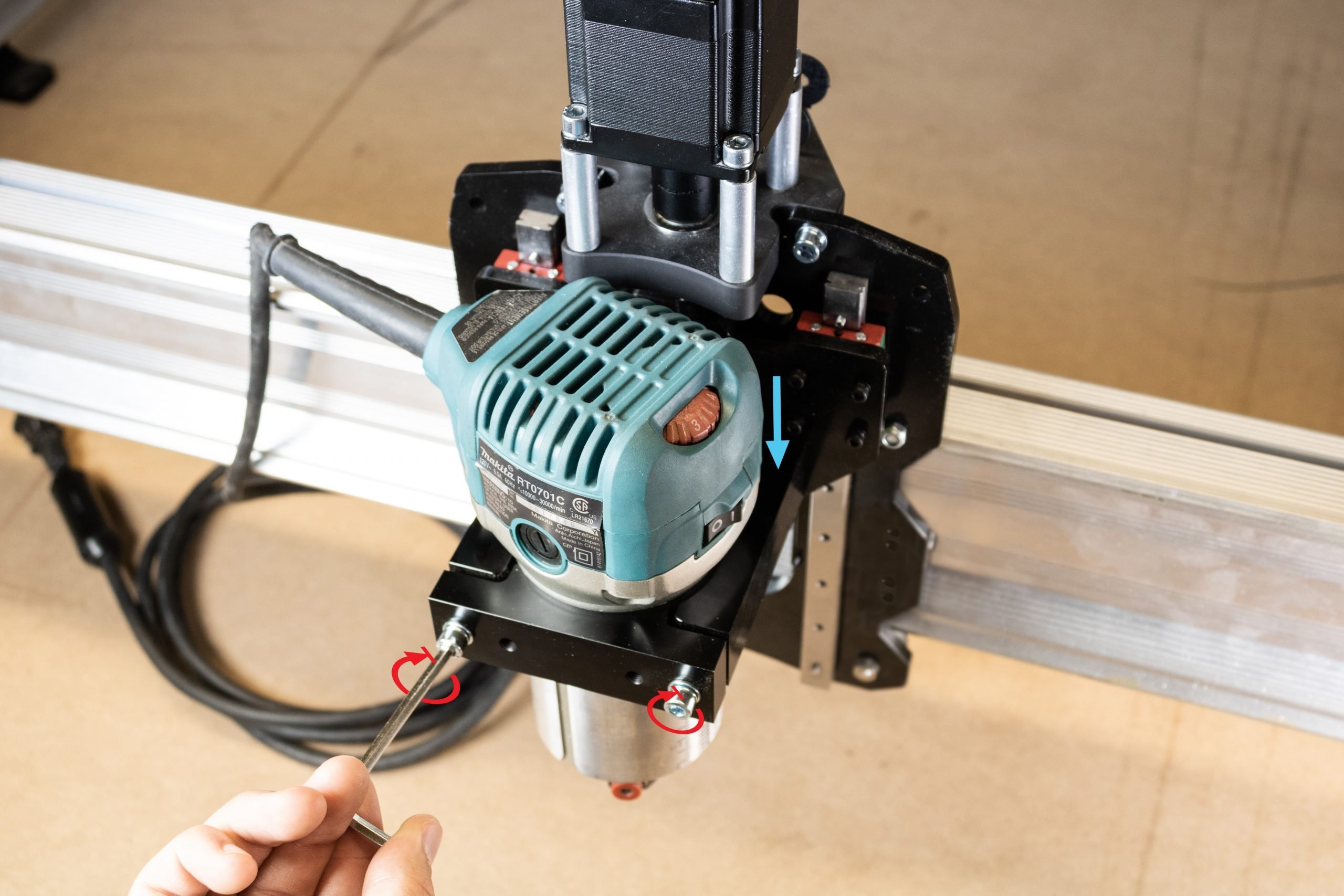
Remove the router from the router mount by loosening the two M5 screws at the front of the router mount. Slide the router body out and remove any zip ties holding the router power cord if applicable. Set the router aside for re-installation later on.
Parts to be reused
Set aside any cables removed, router, as well as the shorter Y-axis drag chain.
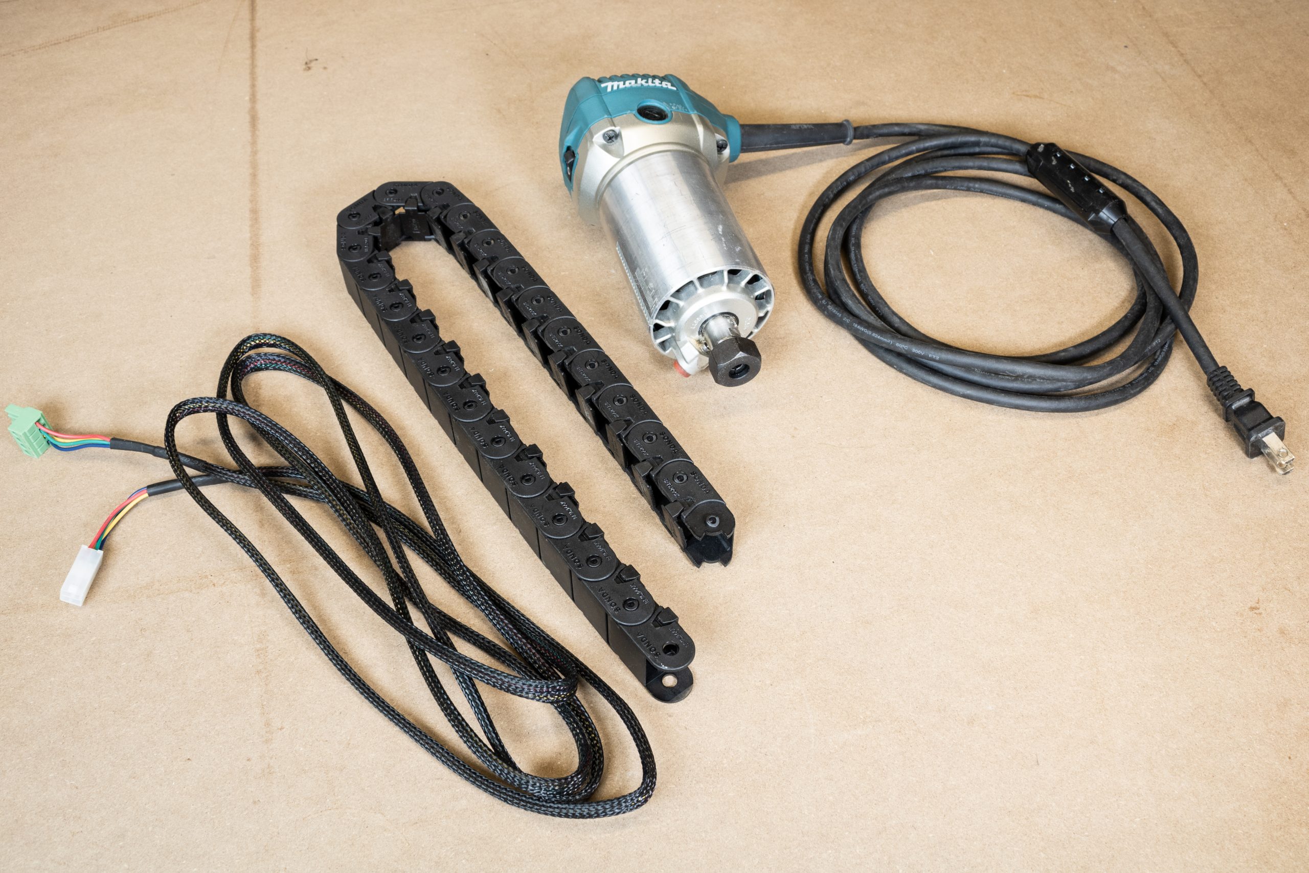
Discard the longer X-axis drag chain – this won’t be reused during assembly.
X-axis Disassembly
Dismounting machine
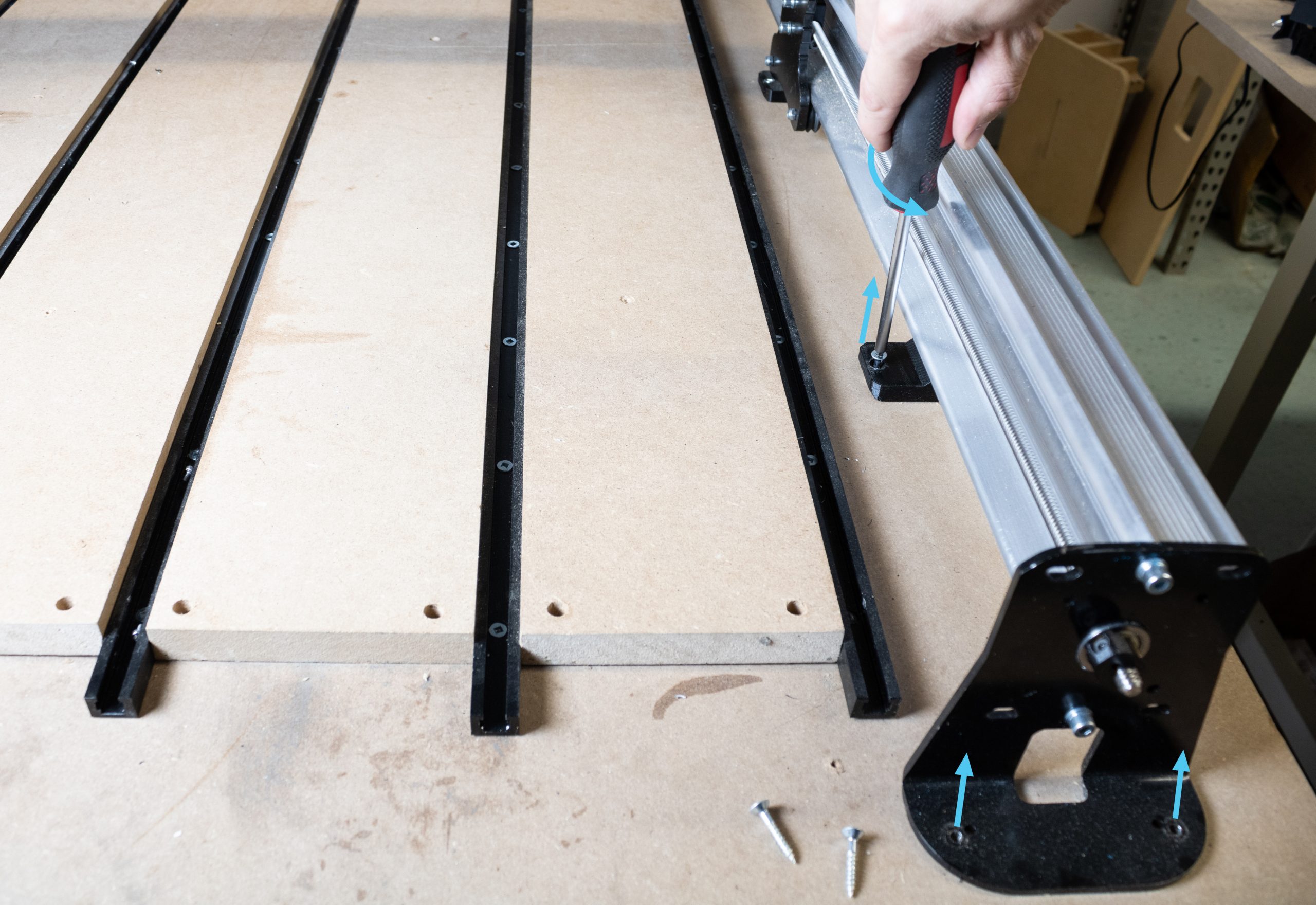
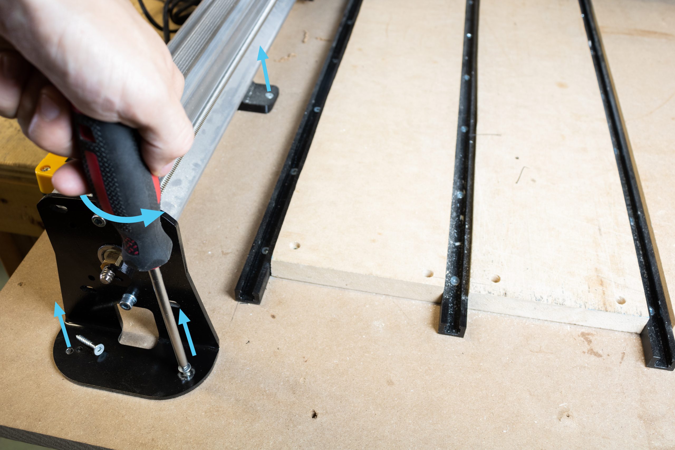
Before beginning the disassembly and replacement of components which make up the X-axis of the machine, start by unmounting the machine from your current wasteboard. Undo each of the eight wood screws installed on the left and right sides of your machine.
X-axis motor and lead screw removal
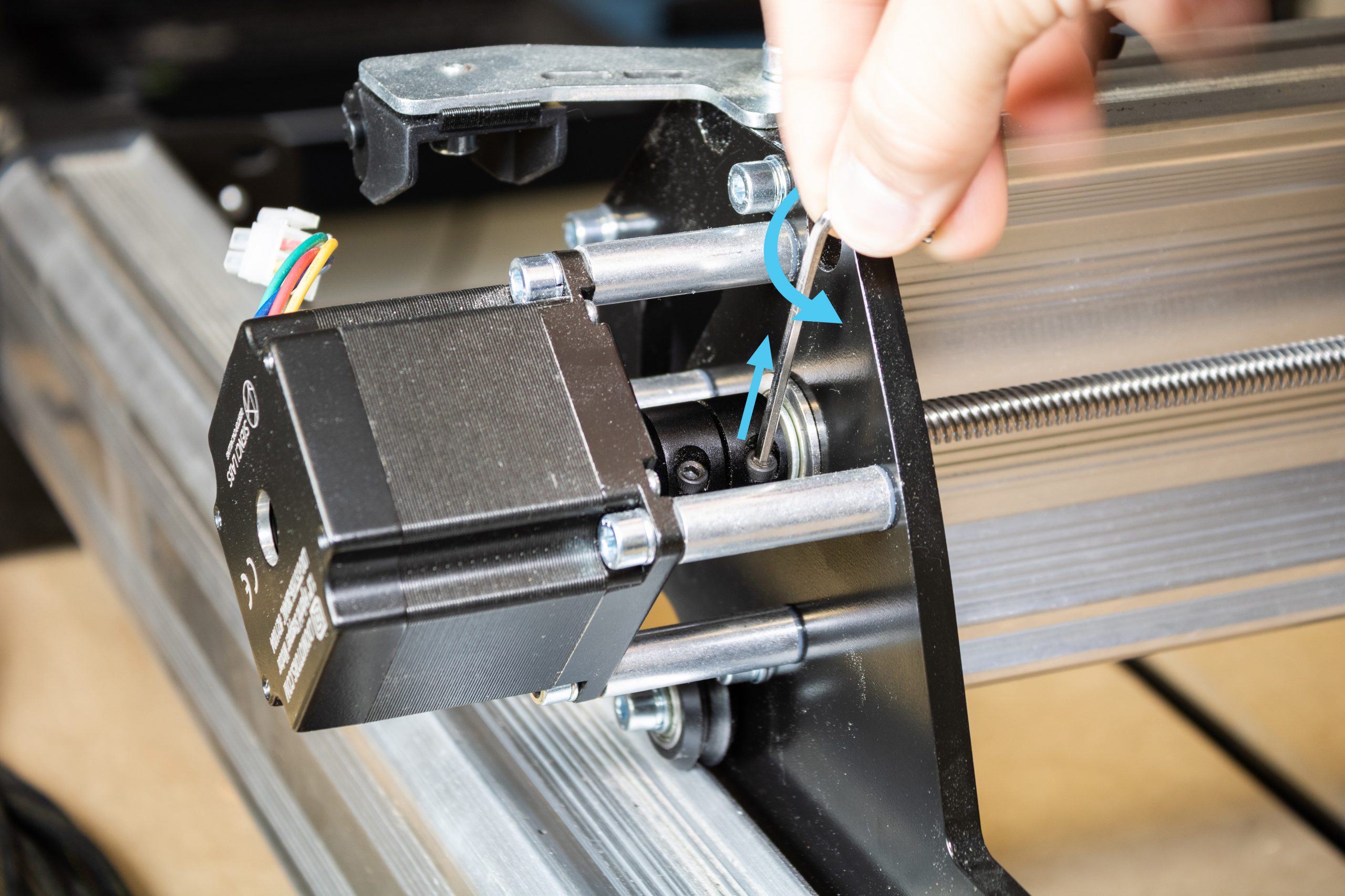
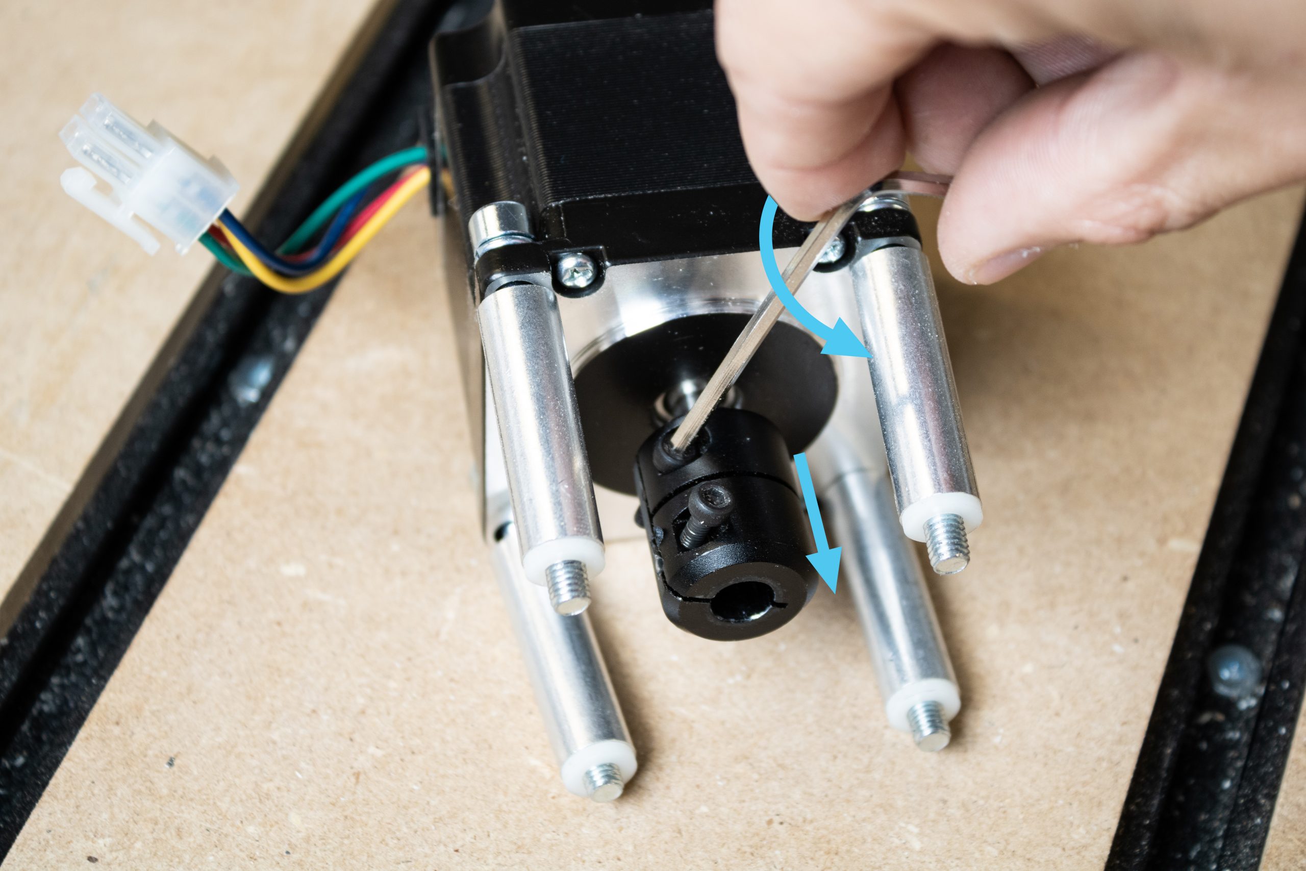
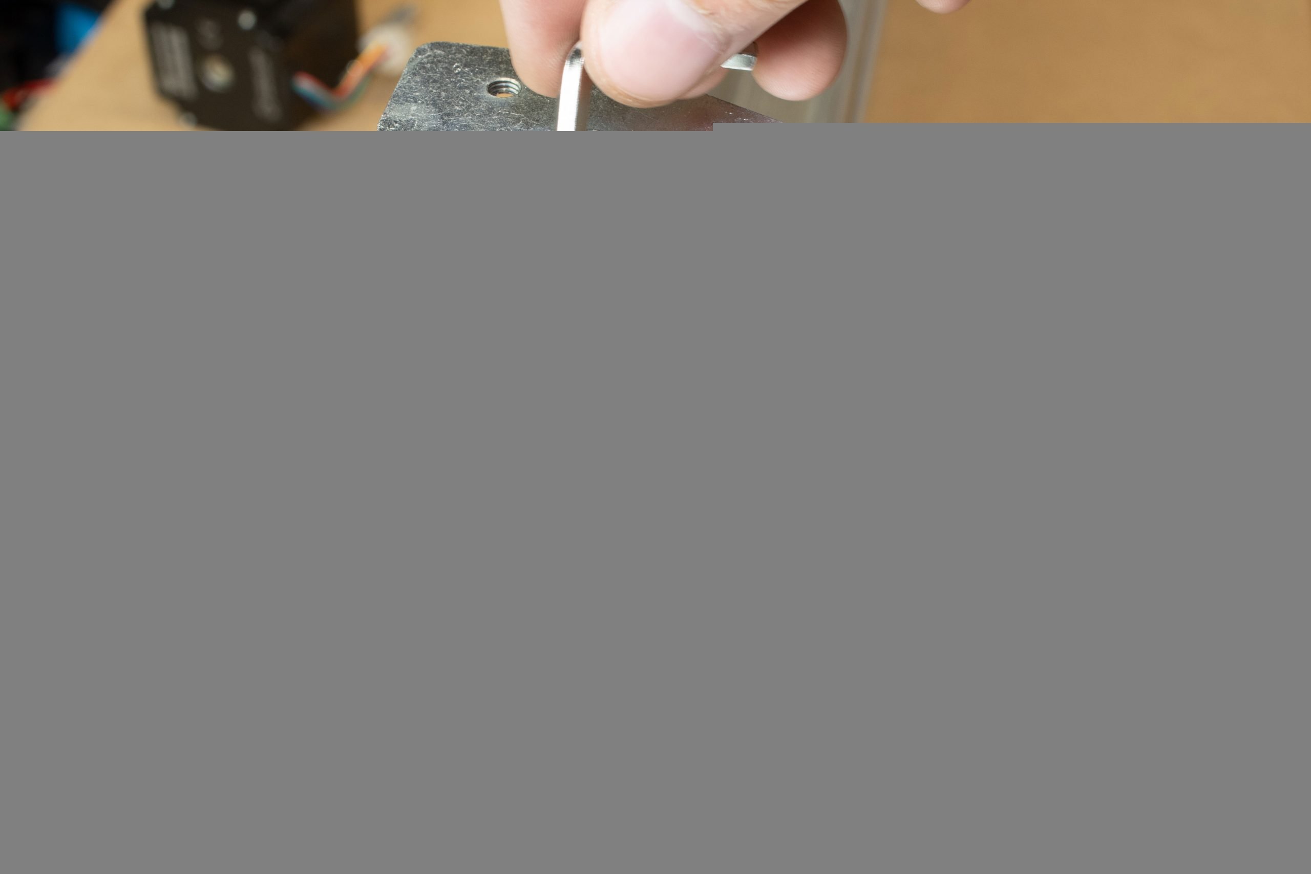
Working backwards from how your LongMill was assembled, we’ll first start by removing the X-axis motor, then X-axis lead screw. First, loosen the coupler clamping screw at the lead screw side as shown.
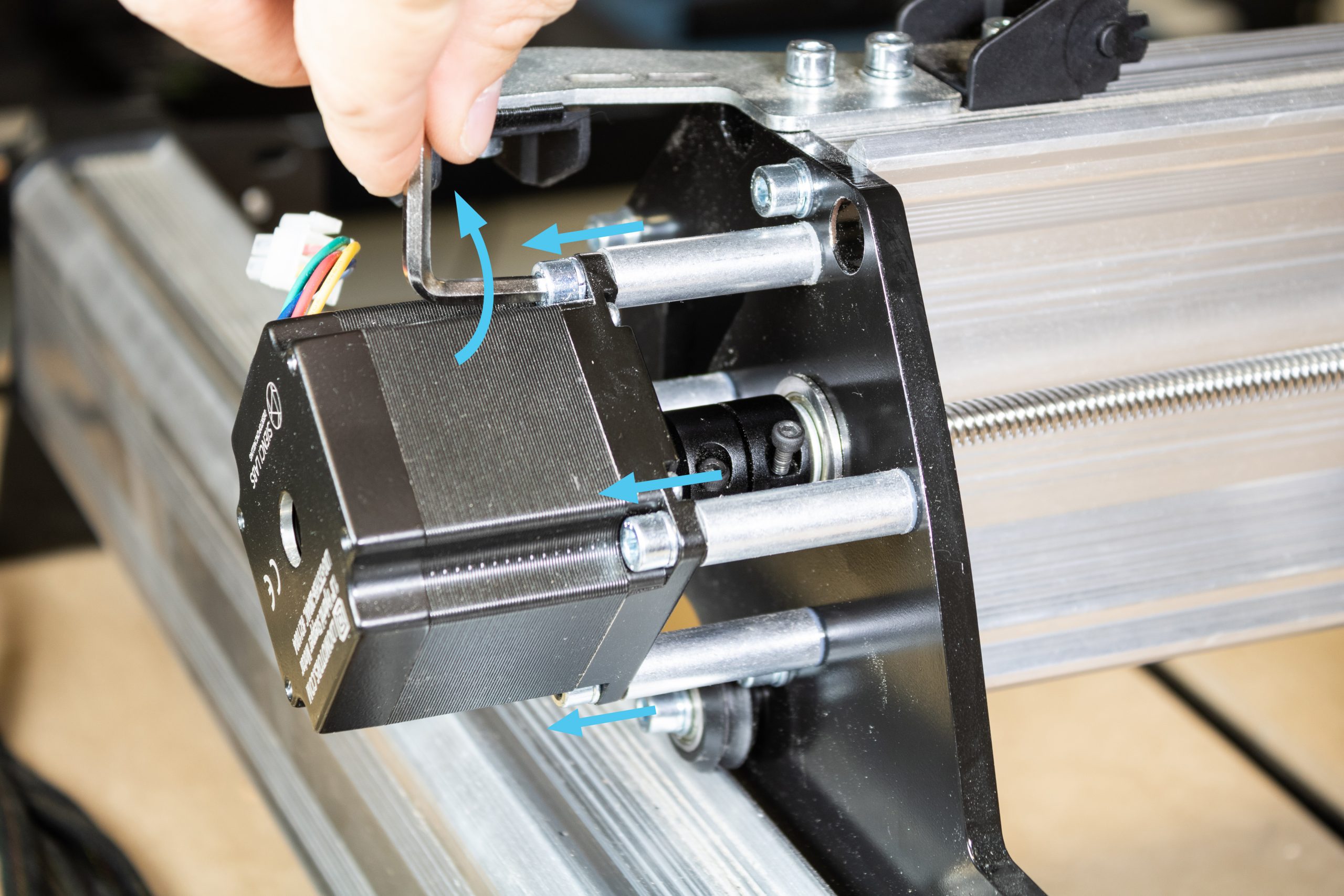
Unscrew each of the four M5-50mm screws holding the motor onto the Y-gantry plate. While doing so, be careful not to lose any of the aluminum standoffs which may slide off the four screws. Set this motor with these screws and standoffs aside for now – these will be reused later.
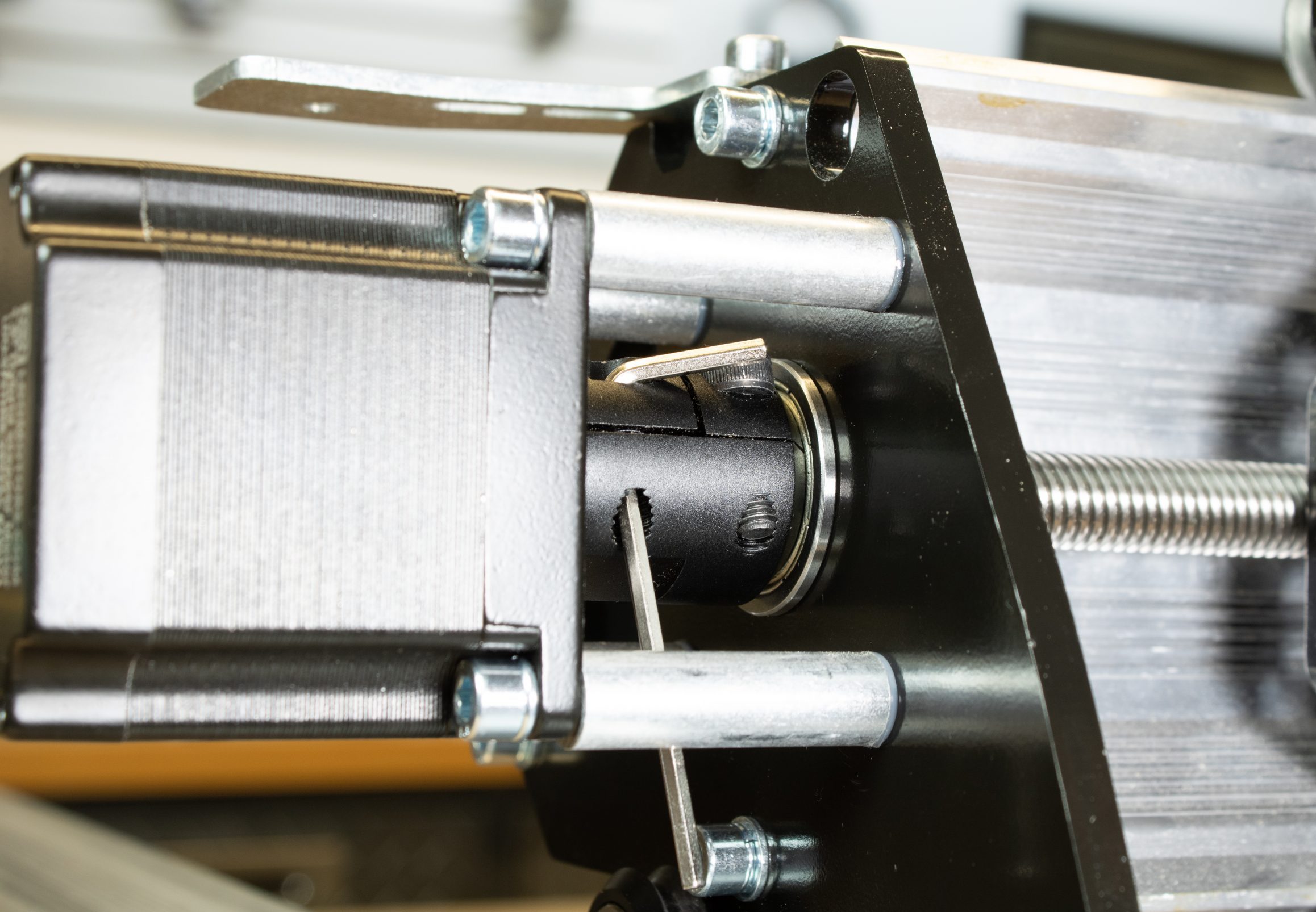
On the removed X-axis motor assembly, loosen the coupler screw at the motor side, and remove this coupler from the motor.
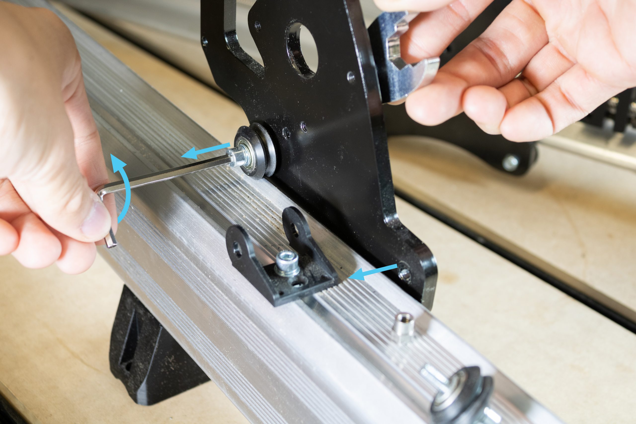
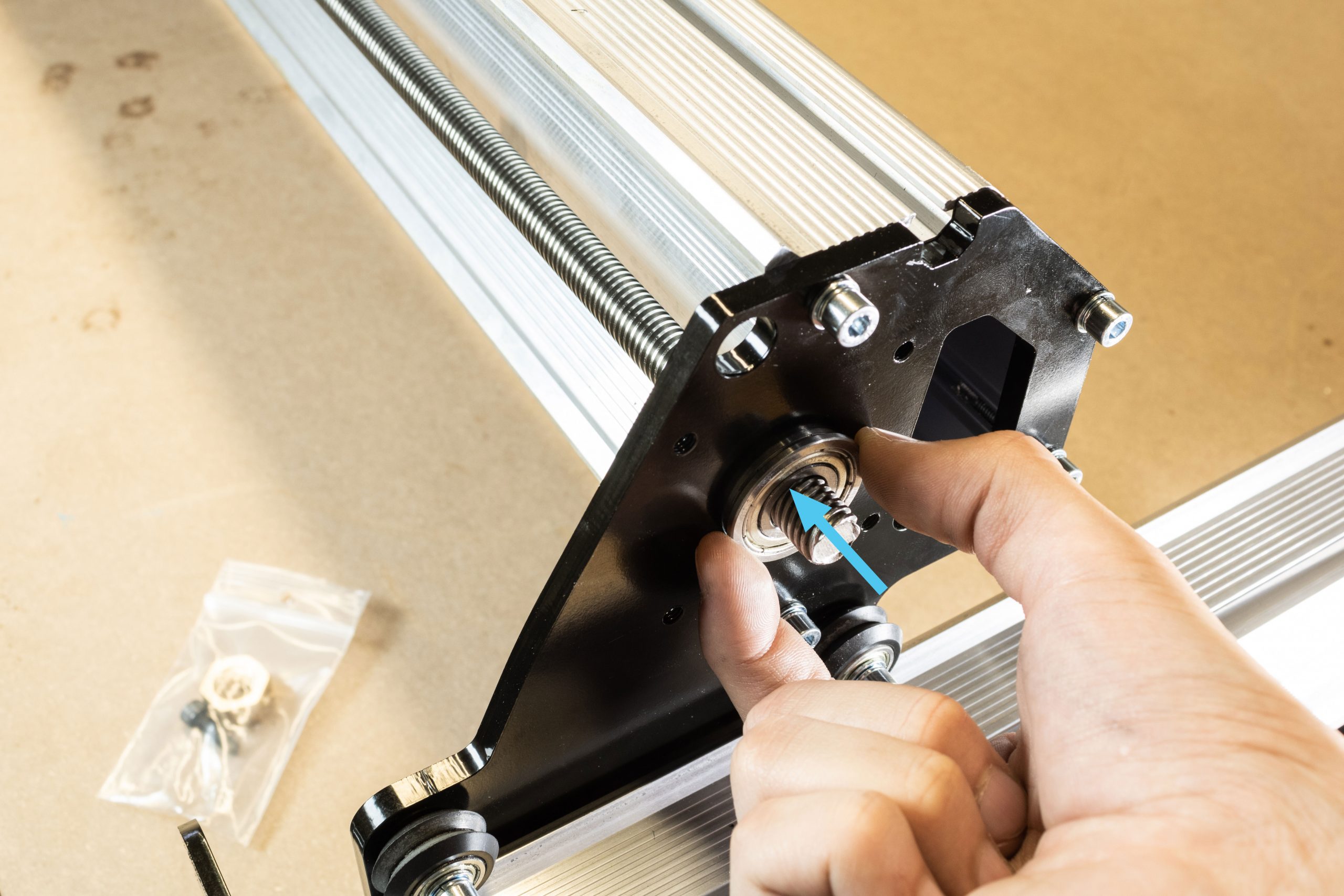
At the left side of the machine where the motor assembly was removed, slide the flange bearing out of the Y-gantry plate and off of the lead screw.
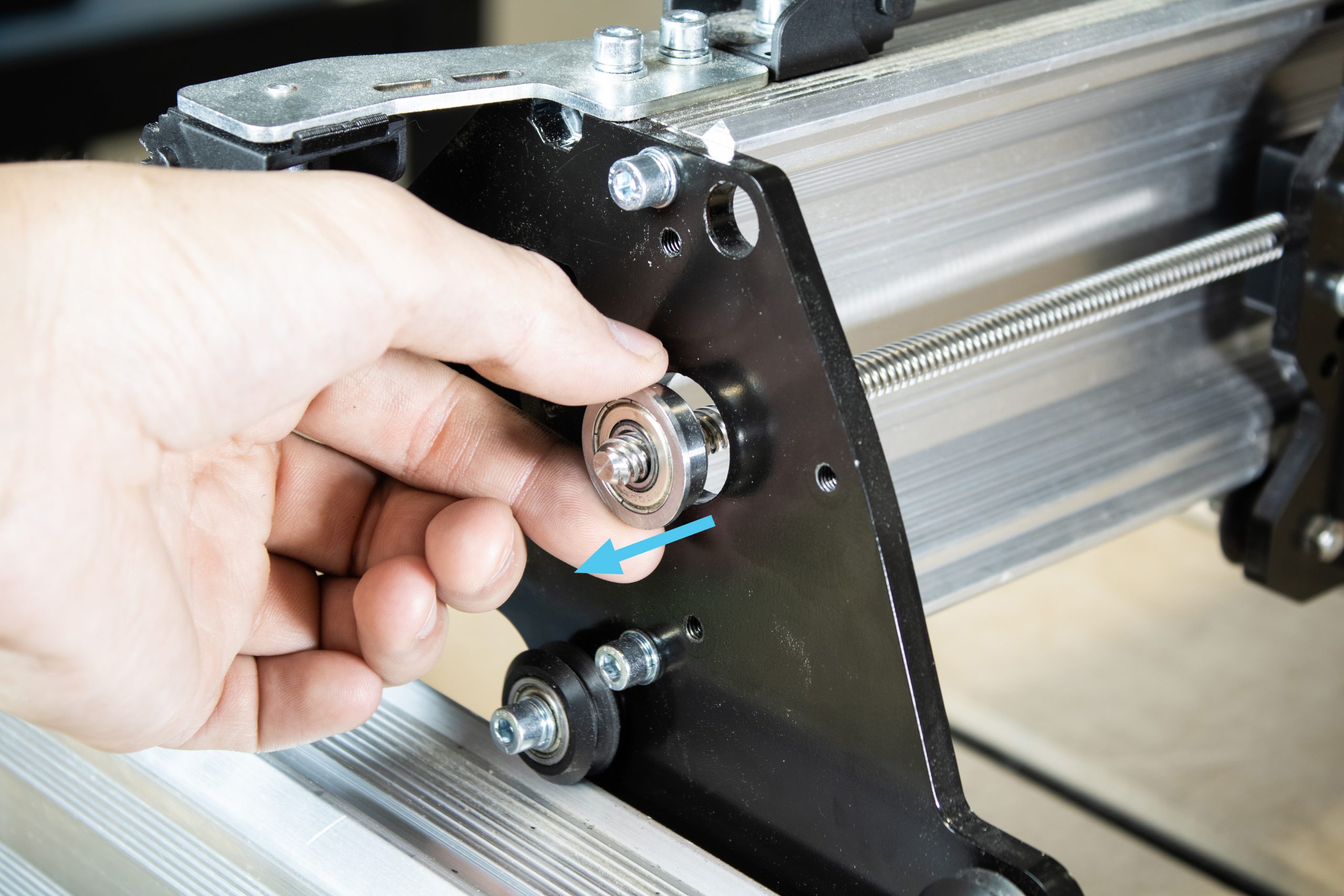
At the right side of the machine pull on the other bearing to start rolling the XZ-axis assembly toward you and separate the bearing from the plate.

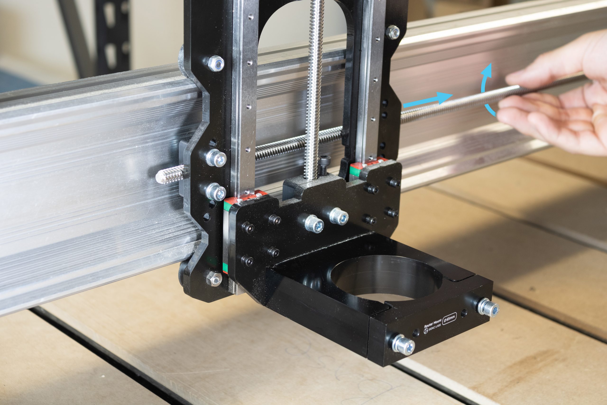
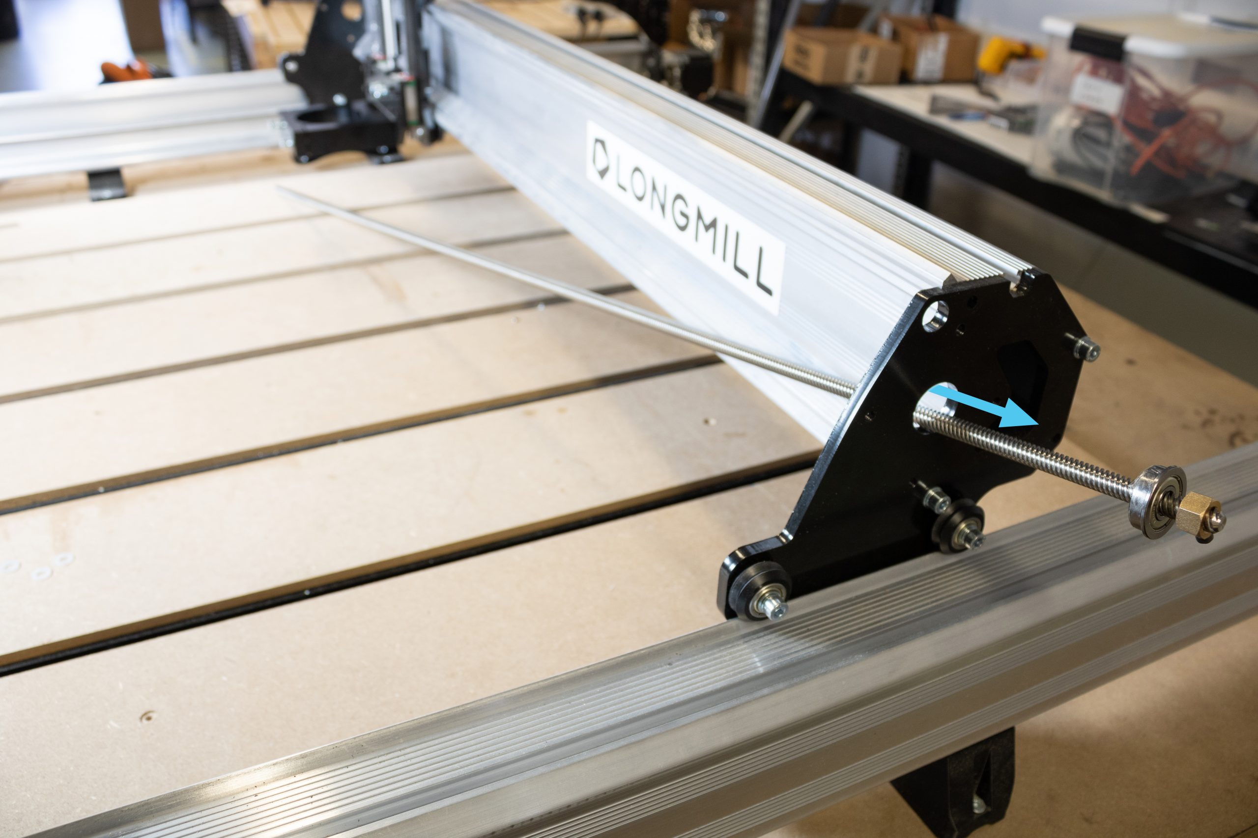
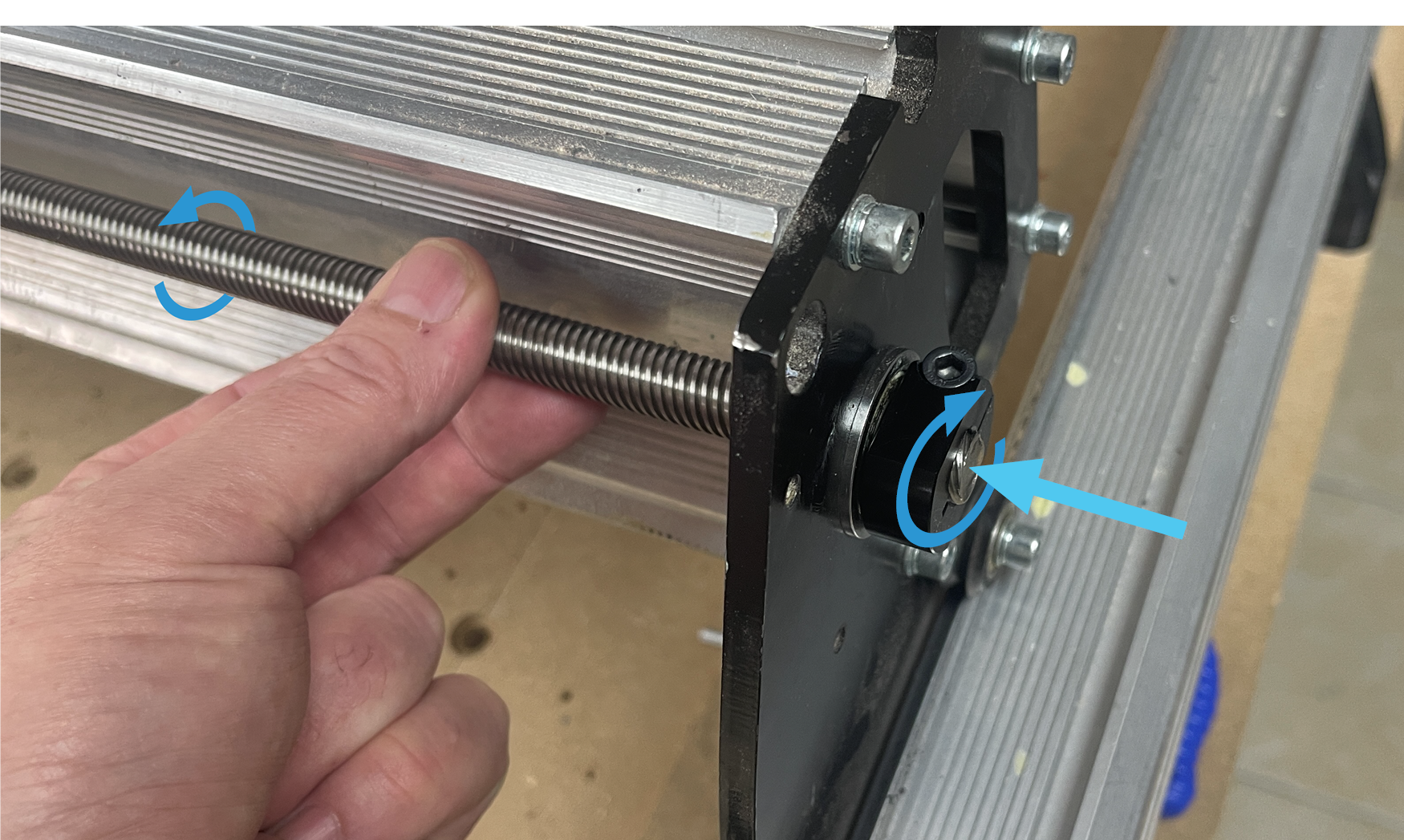
Turn the lead screw counter-clockwise by hand to unthread it from behind the XZ gantry assembly. Once fully unthreaded, remove the lead screw from the machine by removing it from the right side. This lead screw can be discarded as it will not be reused later on.
X-axis rail disassembly
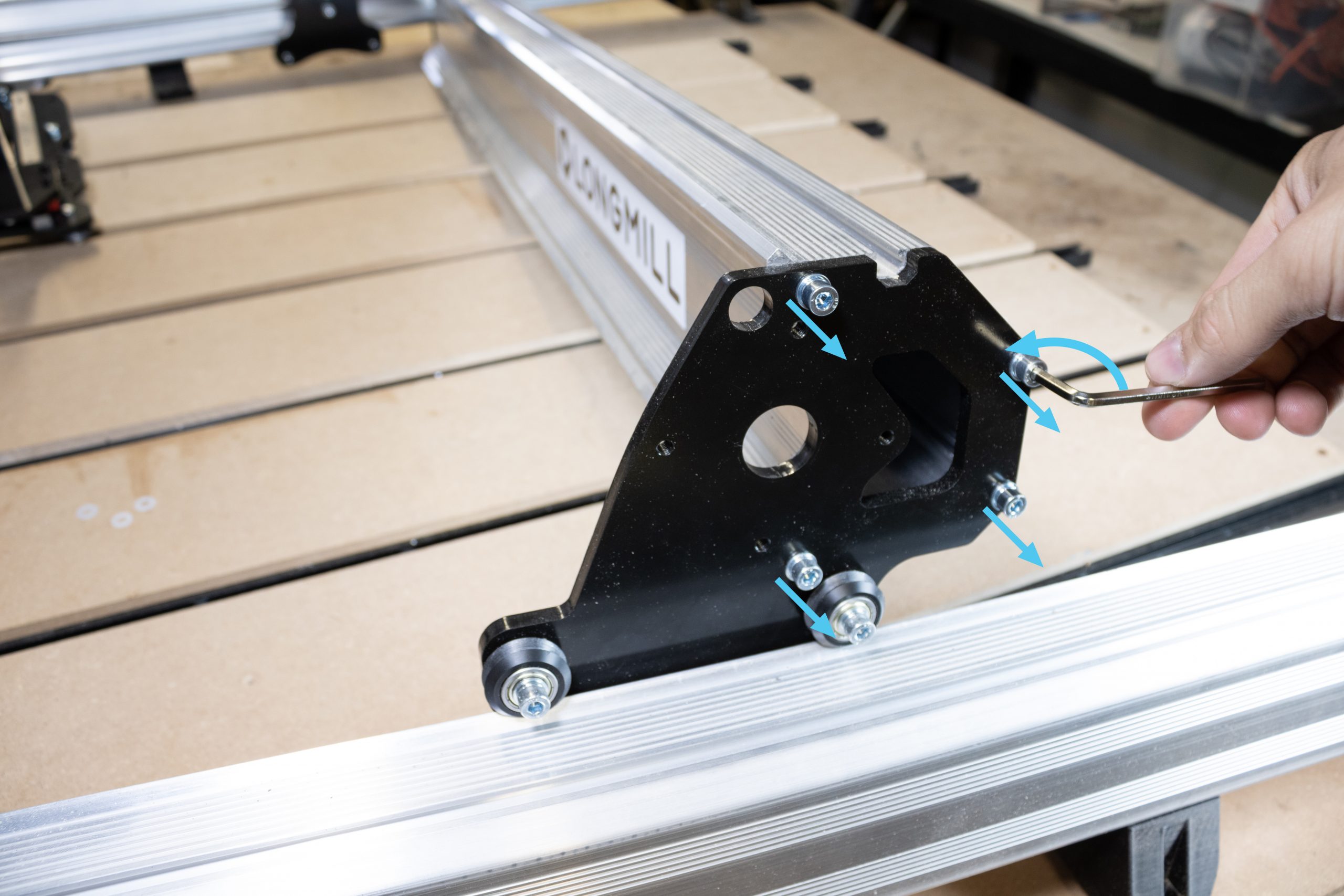
Remove the four M5-25mm screws on the left Y-gantry plate as shown, leaving the X-axis rail to rest on the drag chain mount.
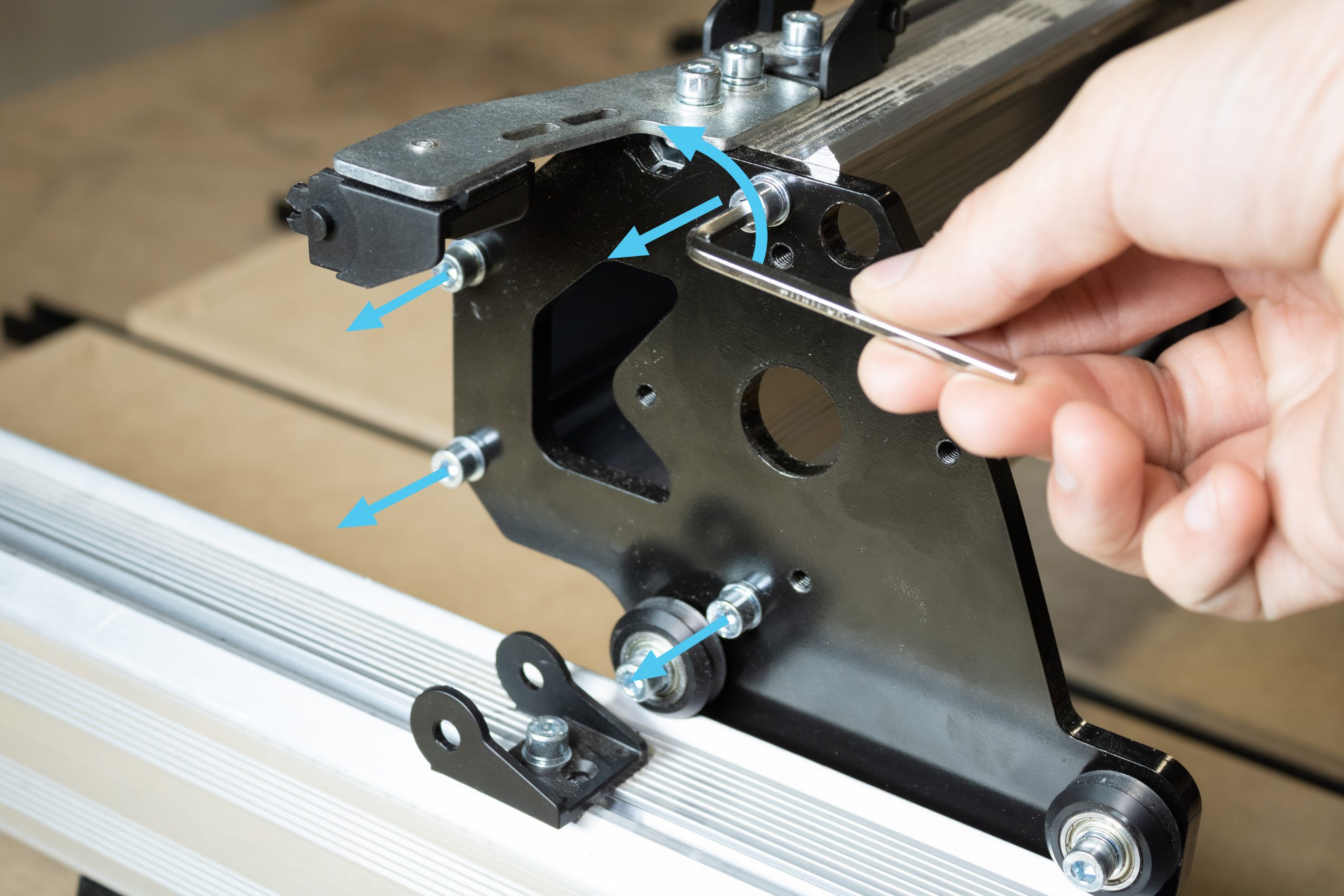
Lift the X-axis rail slightly, then pull out the entire left Y-axis rail and gantry from underneath. Rest the X-axis rail on the wasteboard for now.
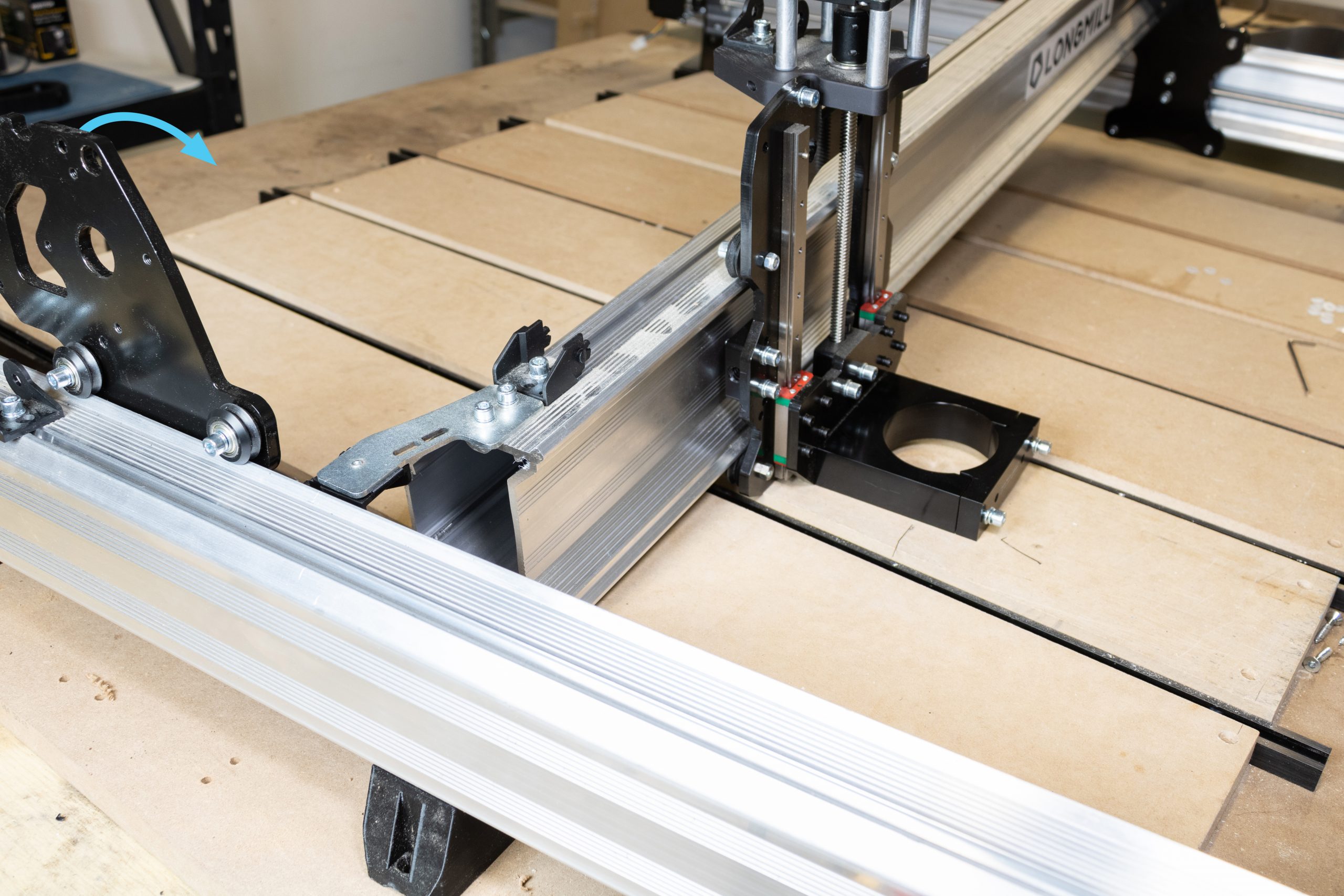
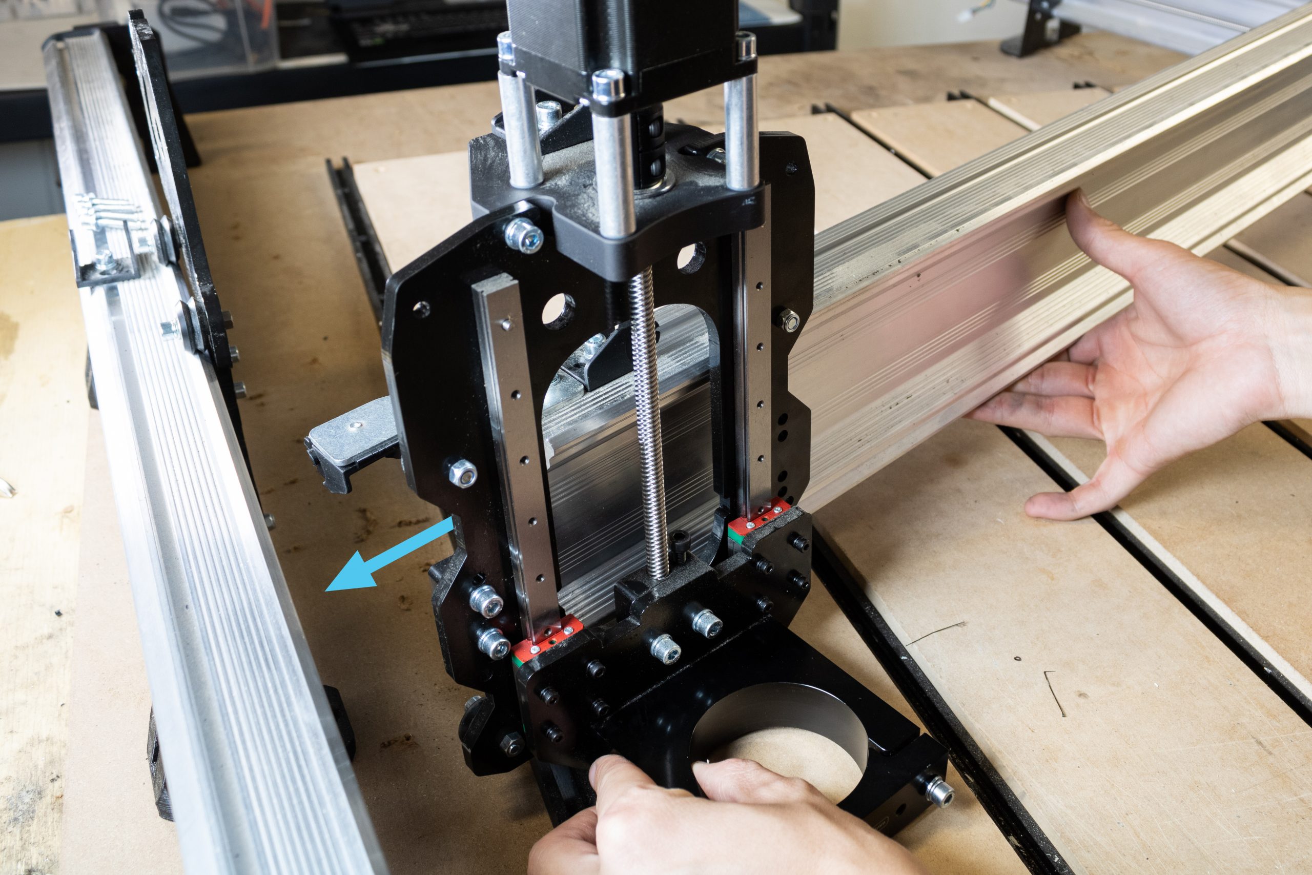
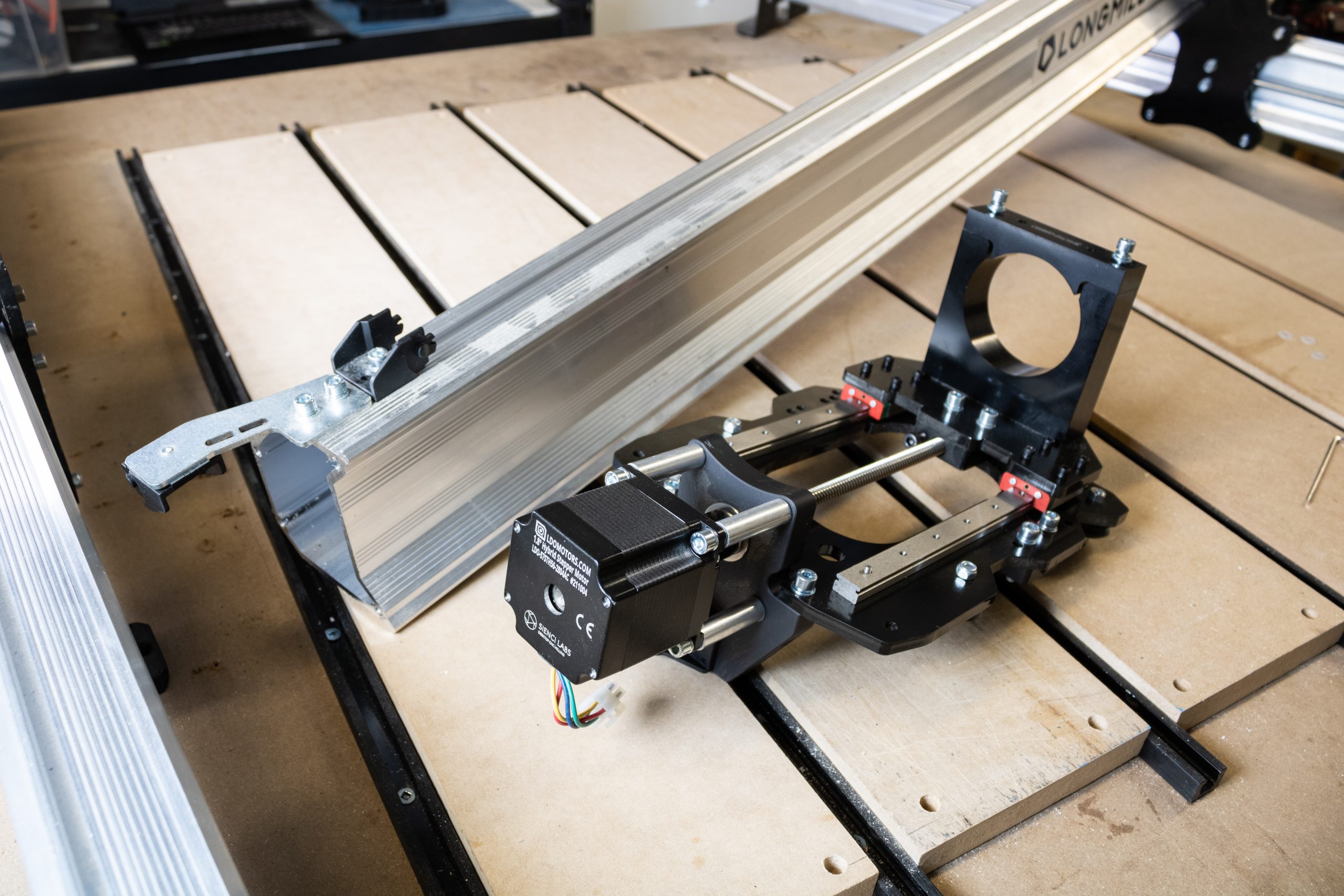
Slide XZ gantry assembly to the left, removing it from the X-axis rail entirely.
At the right Y-gantry plate, undo the four M5-25mm screws to completely detach the X-axis rail.
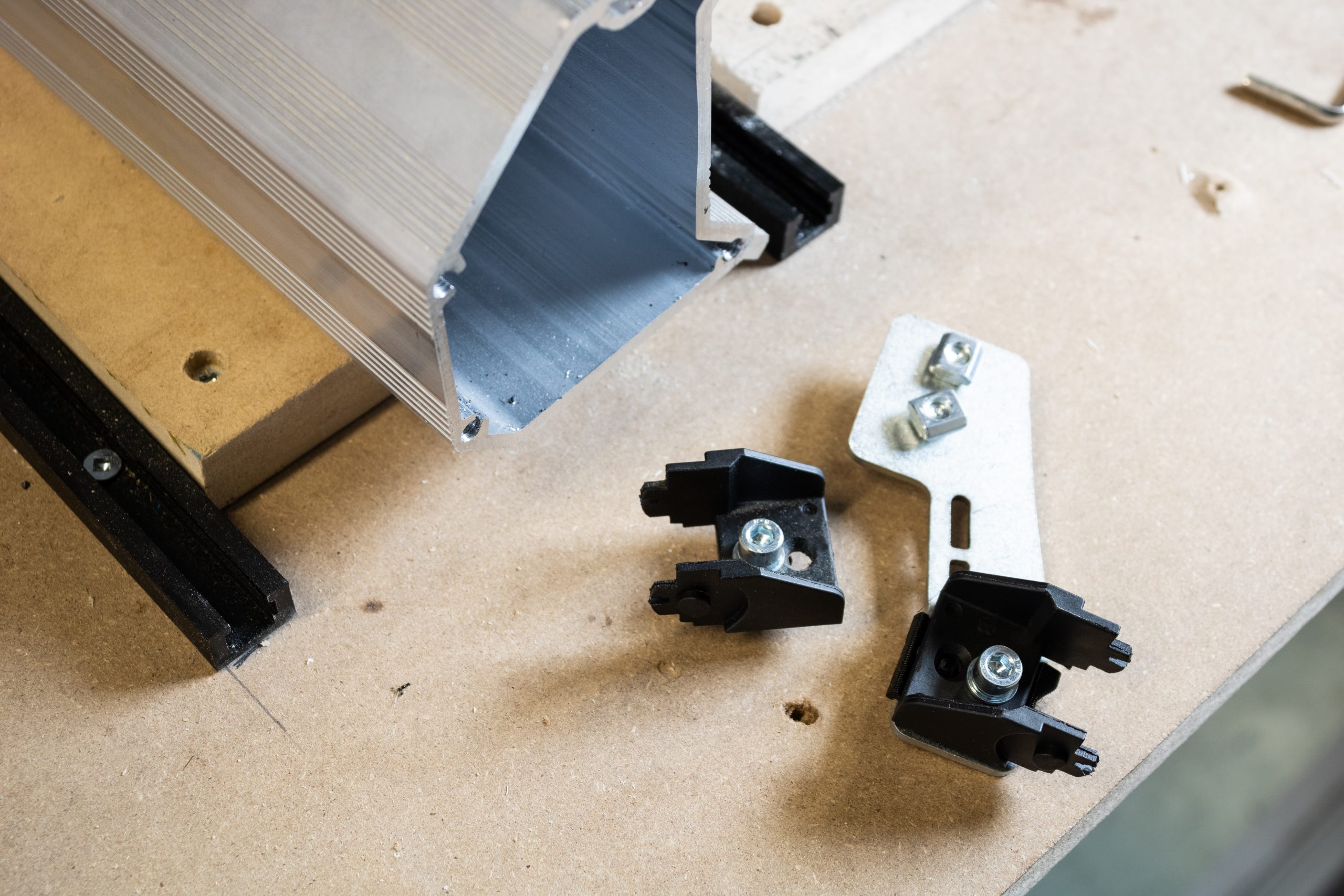
Remove the drag chain mount and drag chain end link from the left side of the X-axis rail by loosening all three M5-10mm bolts and sliding the components off. Set the X-axis rail and drag chain mount with screws aside. The drag chain mount and drag chain end link will be getting reused later, but the X-axis rail will of course not be.
At this point, you’ll want to transfer the two Y-axis rail assemblies and XZ-gantry assembly onto your larger MDF waste board since the soon-to-be 48×30″ machine likely will not fit on your existing wasteboard anymore.
Y-axis gantry disassembly
Since the left and right Y-axis rails are perfectly mirrored assemblies, repeat any of the steps for this section on both Y-axis rail assemblies. Start by removing the two M5-25mm screws which attach the Y-gantry plate to the delrin nut behind it.

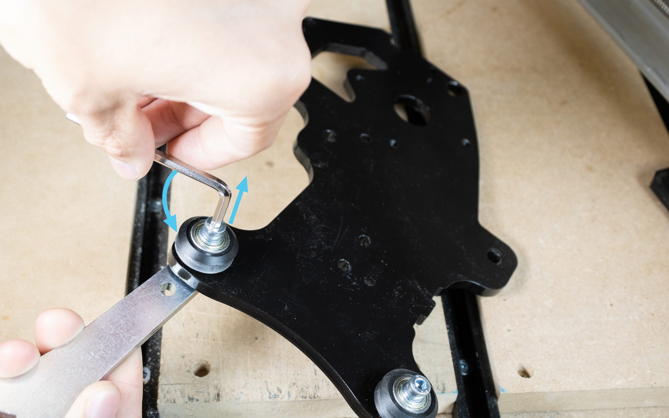
Next, remove the upper two V-wheels from the Y-gantry plate to allow the Y-gantry plate to detach from the rail.
Once both Y-gantry plates are detached from the rails, remove the lower set of V-wheels as well and set all V-wheels aside with their associated washers and nuts.
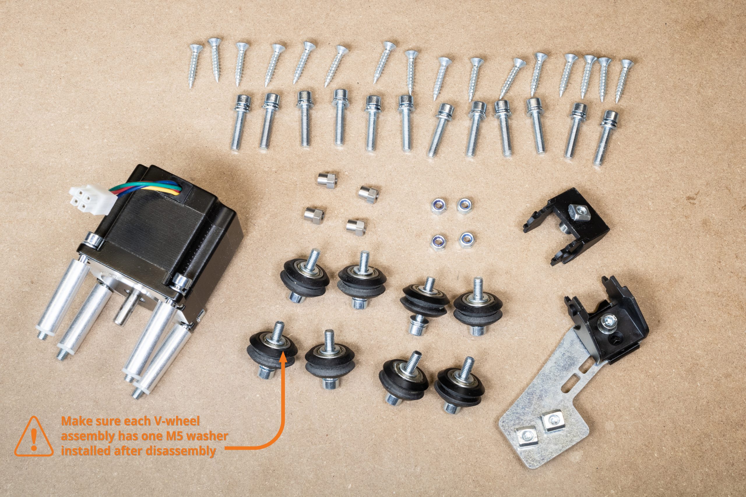
Parts to reuse
At the end of the disassembly of the X-axis, stop to make sure you haven’t lost any parts which will be reused later. These are all shown below, any other parts not shown can be discarded.
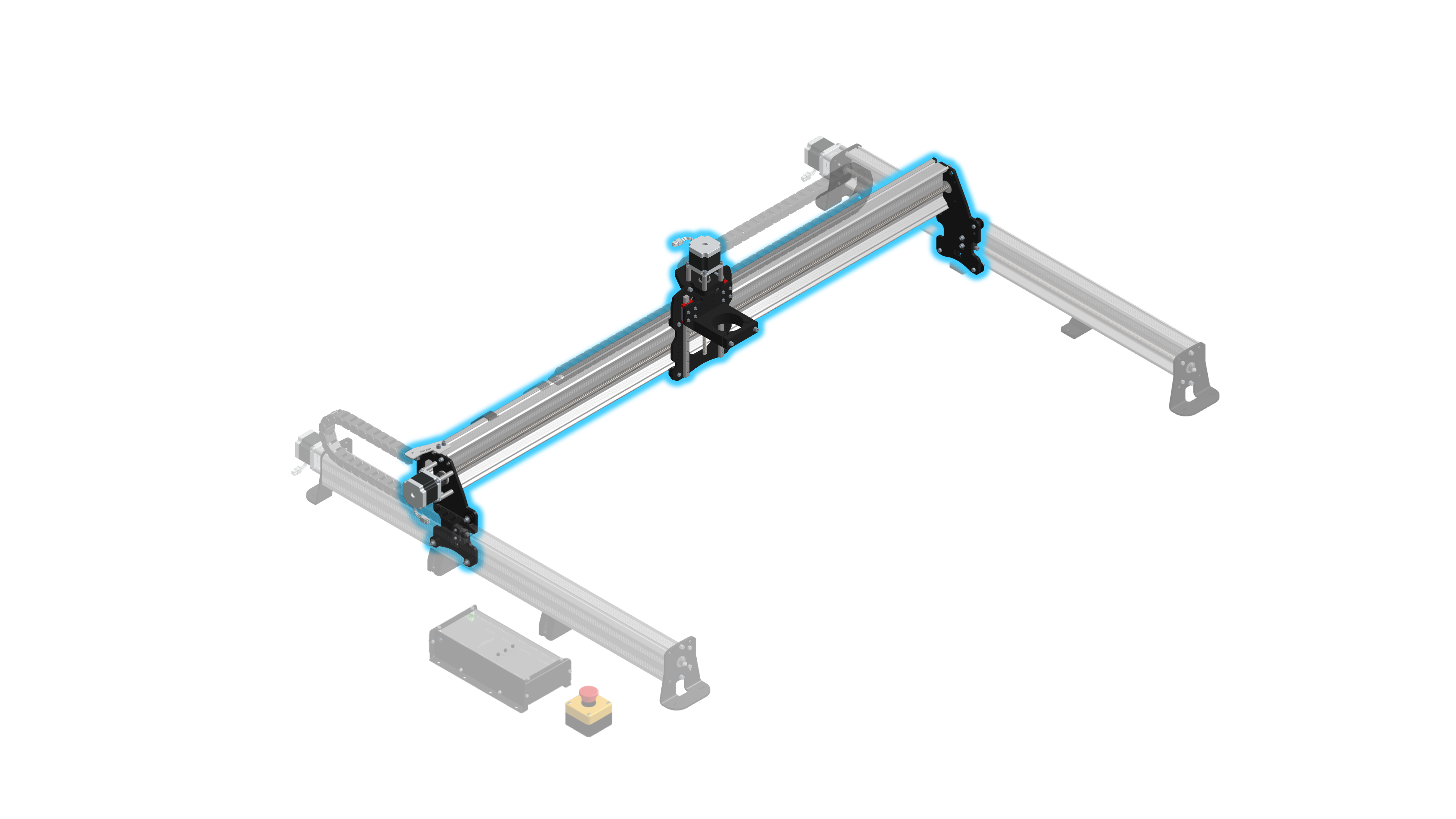
48″ Extension X-axis assembly
EX Y-gantry plate assembly
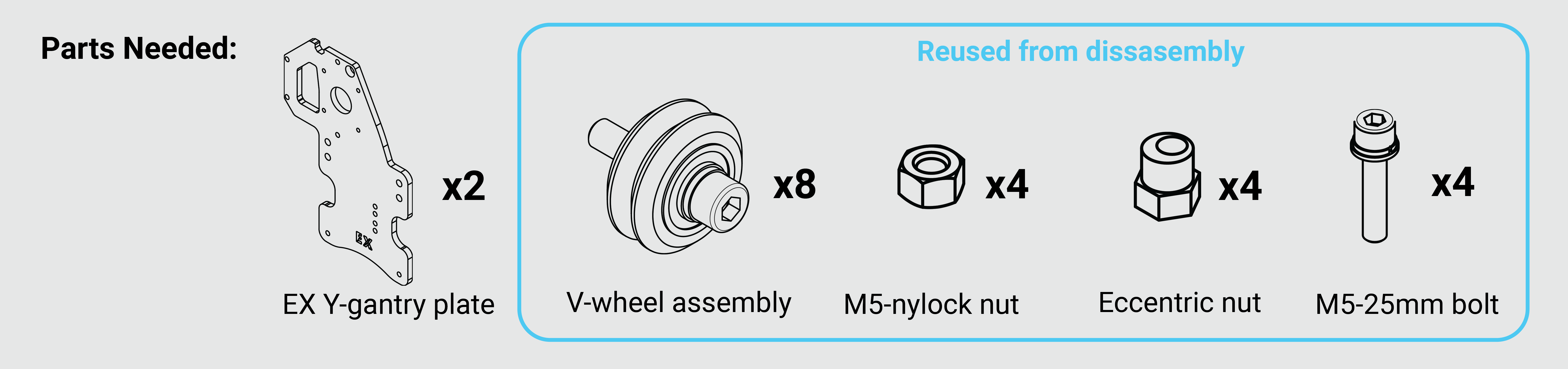
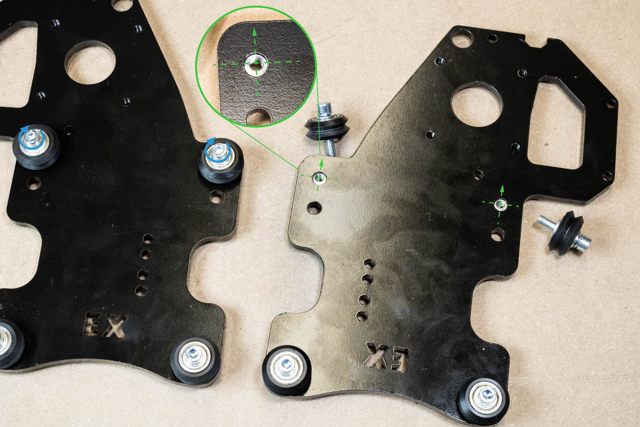
On the new Y-gantry plates included in the extension kit marked ‘EX’, begin installing the V-wheels into the upper holes of the Y-gantry plates. Make sure the eccentric nuts are rotated so that the V-wheels are in their highest ‘open’ position to make assembly easier.
Rest the Y-gantry plates onto the Y-axis rails and install the lower V-wheels into the Y-gantry plate to secure the Y-gantry plate on the rail. Check to make sure the gantries roll/slide easily along the rail.
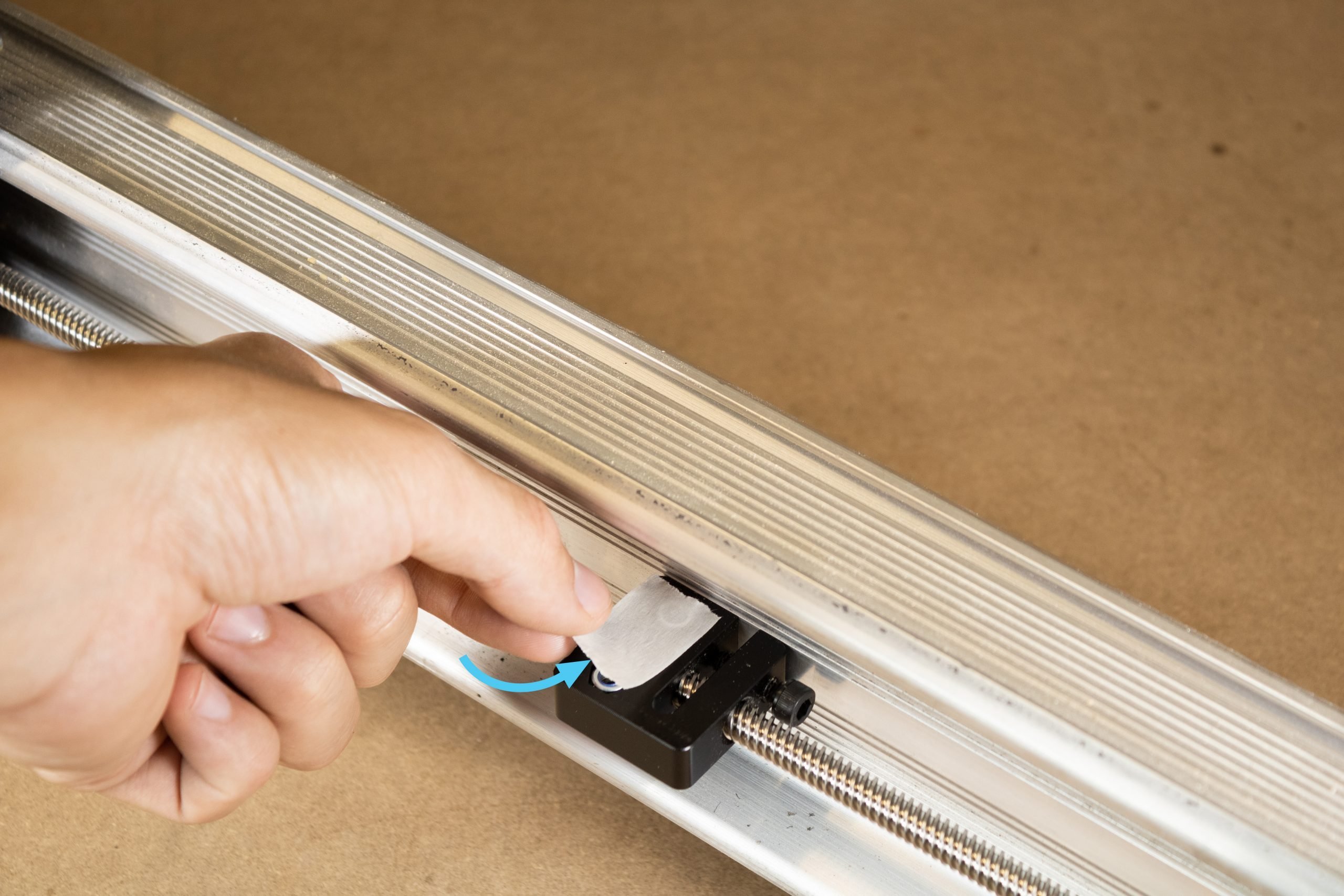
If the two M5-nylock nuts have fallen out of the Y-axis anti-backlash delrin nuts, you’ll want to re-install these. If you find that they fit loose and are continuously falling out, you can apply a small piece of tape to the back of the delrin nut to hold these in place as shown below.
Slide the Y-gantries to line up the highlighted two holes in the plate with the Y-axis delrin nuts.
Fasten the Y-gantry to the delrin nut by using the two M5-25mm screws removed during disassembly. Only tighten these screws until snug.
EX X-axis preparation
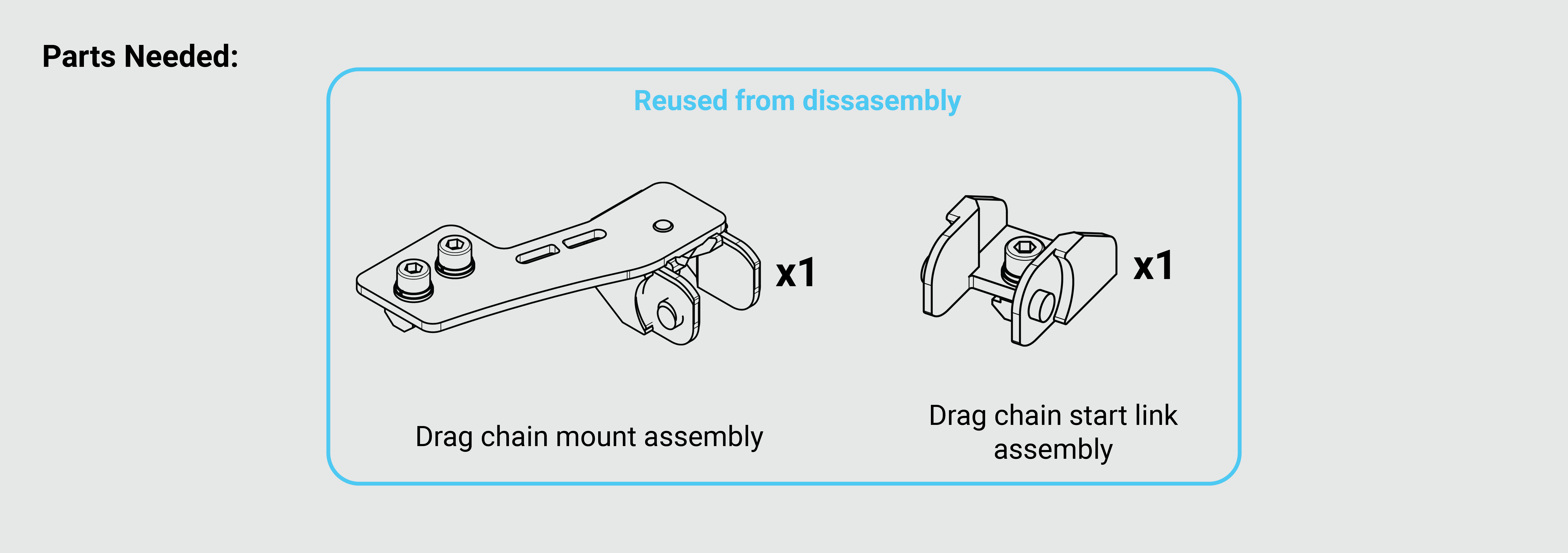
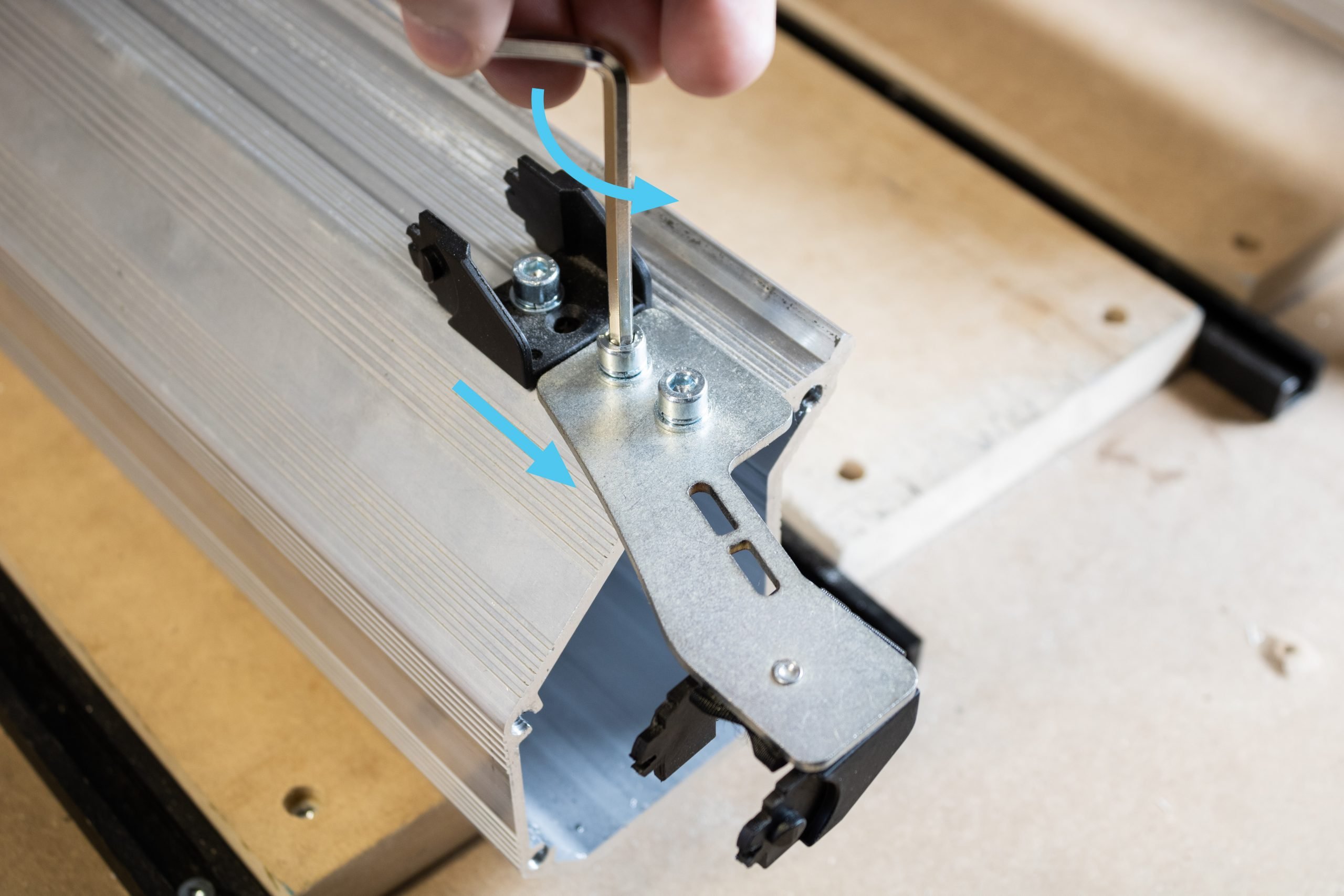
On the new 48″ X-axis rail extrusion, slide the reused drag chain end link assembly into the T-slot using the T-nut.
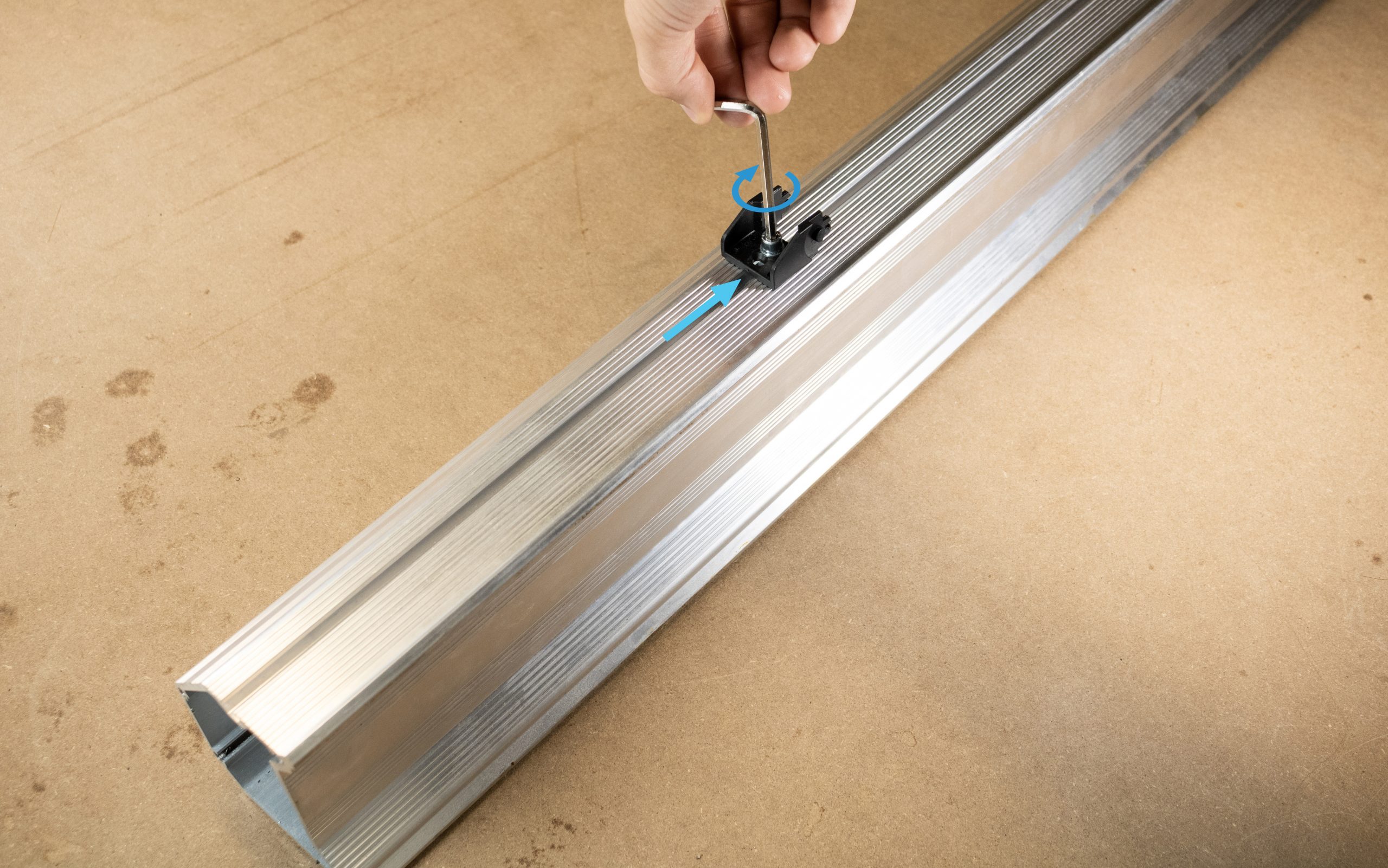
Slide this end link ~10″ away from the end of the X-axis rail, then tighten the screw.
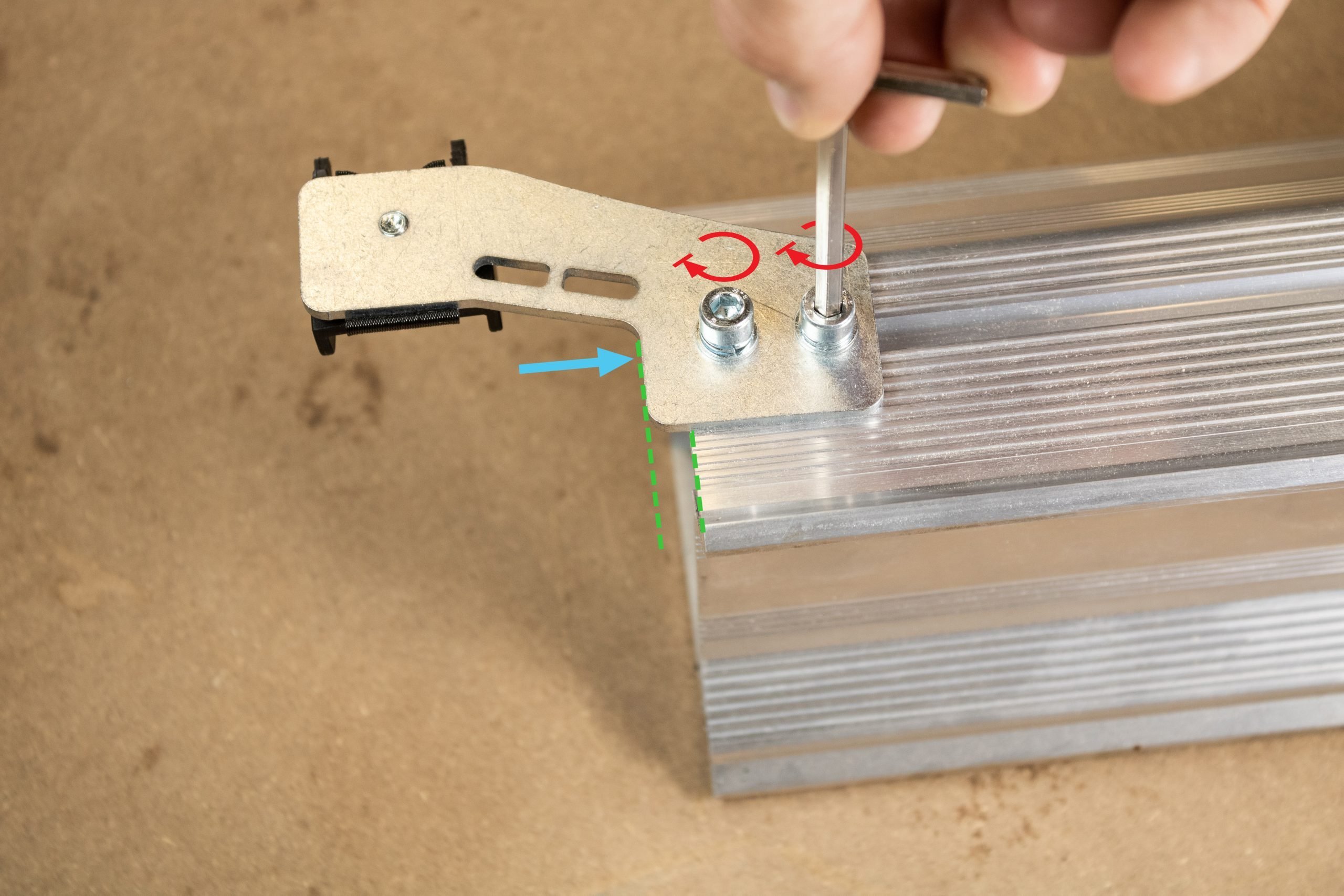
Slide in the drag chain mount by sliding in the two T-nuts into the T-slot of the rail. Fasten the mount by tightening the two screws. Ensure that it is offset from the edge of the rail by about 6mm or ¼” (pictured)
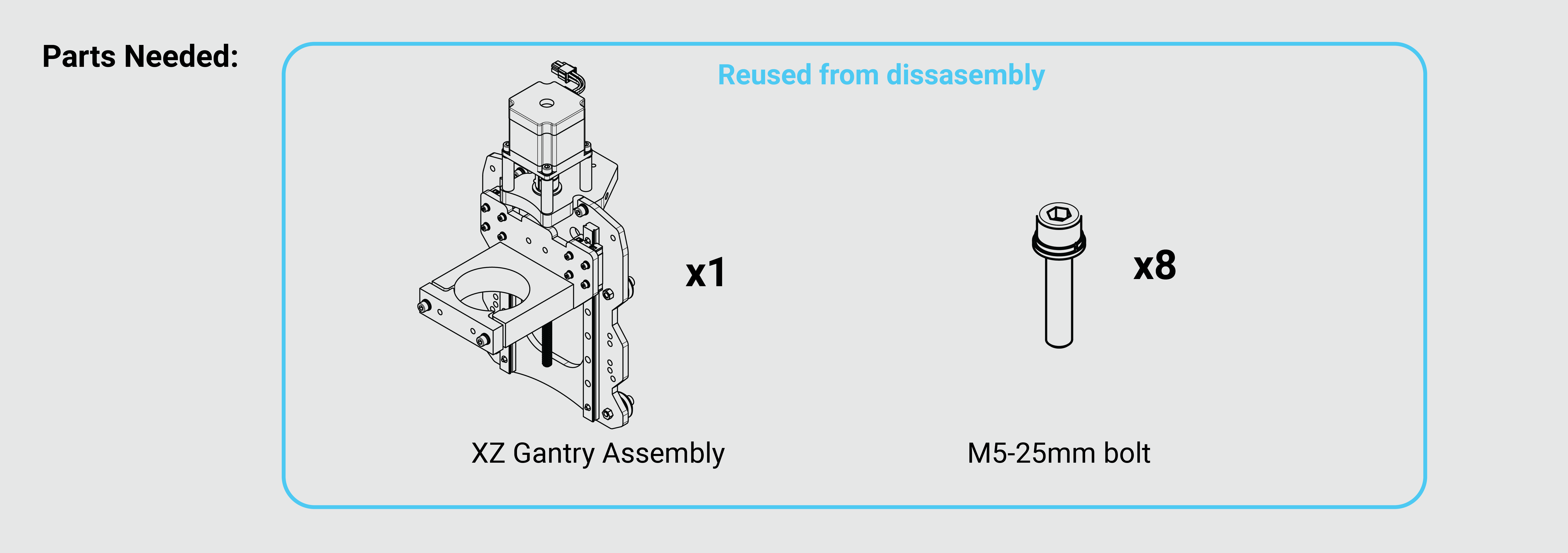
Grab the XZ gantry that was previously removed from the original X-axis rail. To accommodate the larger X-axis lead screw the Delrin nut on the back of the XZ gantry will need to be swapped out with the much larger EX Delrin nut. Remove the two M5-25 screws holding this Delrin nut on.
Once separated from the XZ gantry, remove the nylock nuts from this Delrin nut. Use one of the two screws just removed to push the nuts out from the opposite side.
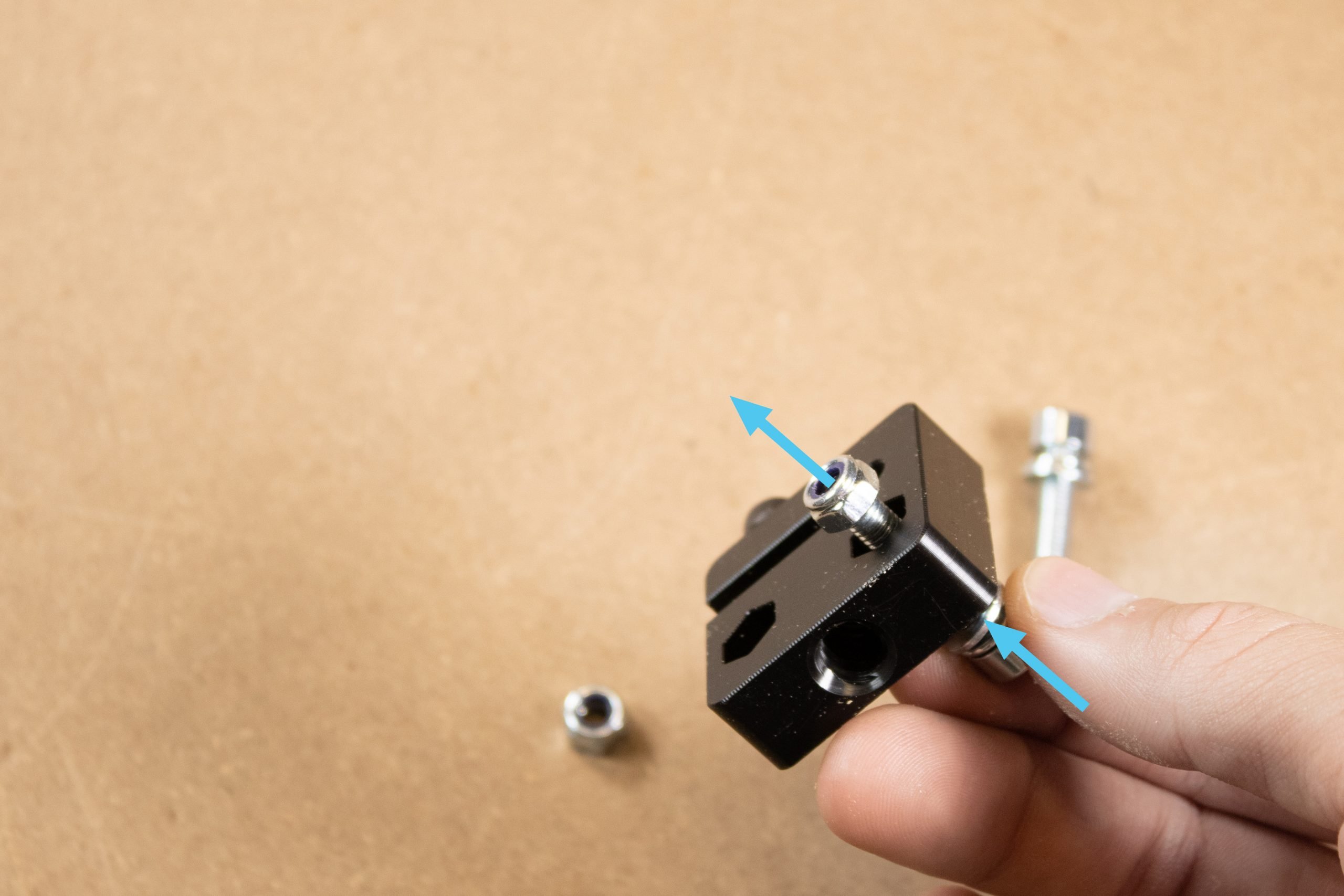
Install these M5-nylock nuts into the larger EX Delrin nut.
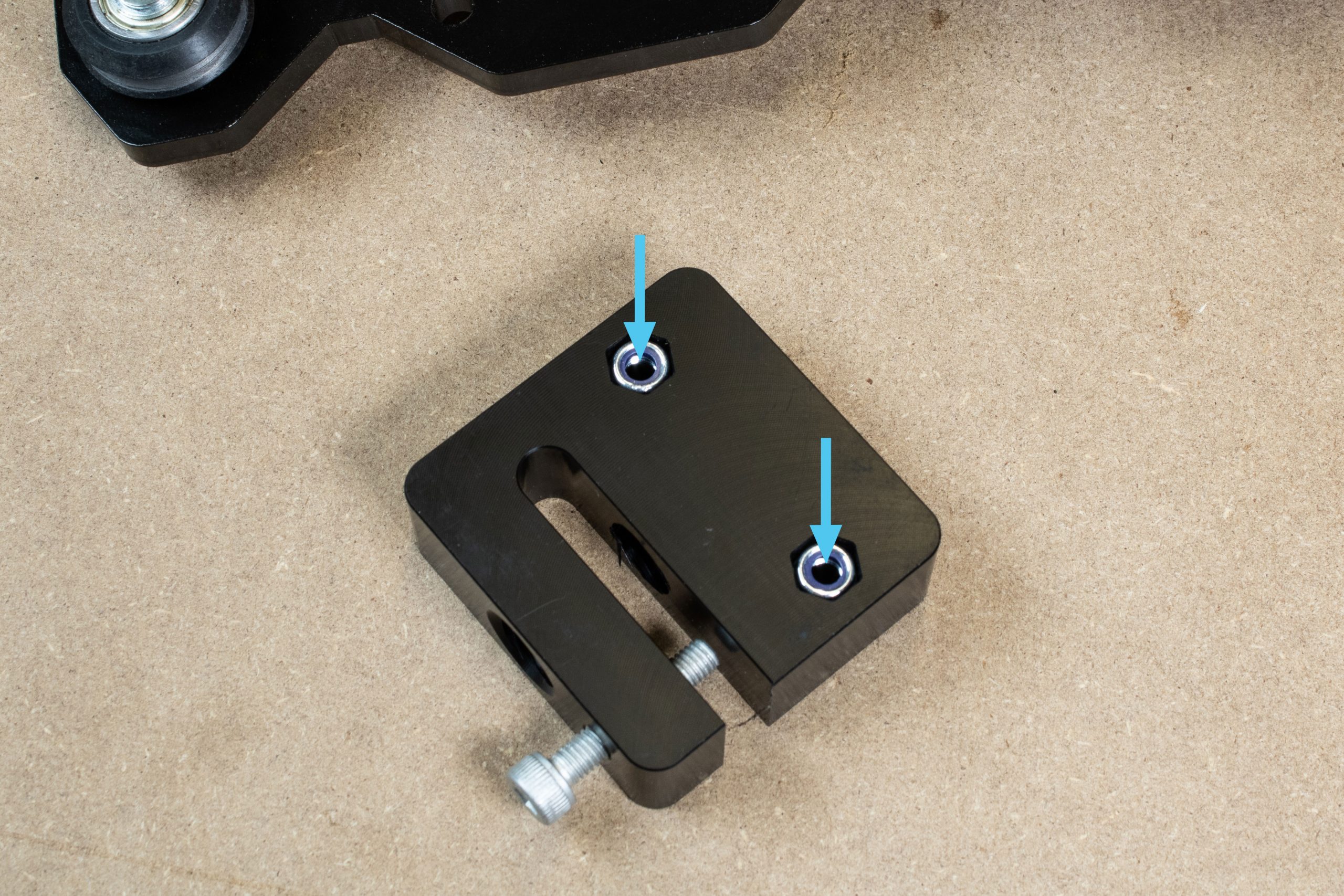
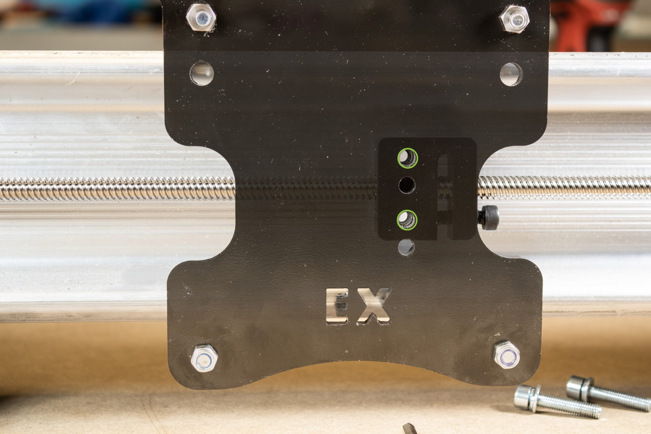
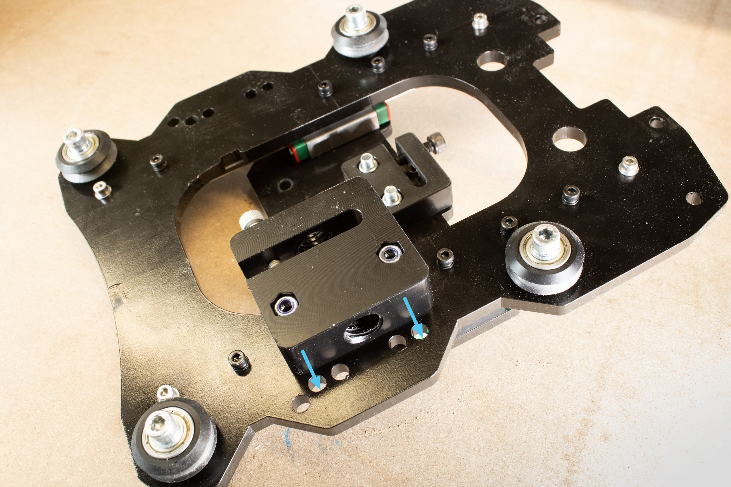
The EX delrin nut is now installed onto the XZ gantry using the two further holes circled below. Insert the M5-25 bolts into the front of the XZ gantry and into the EX Delrin nut.
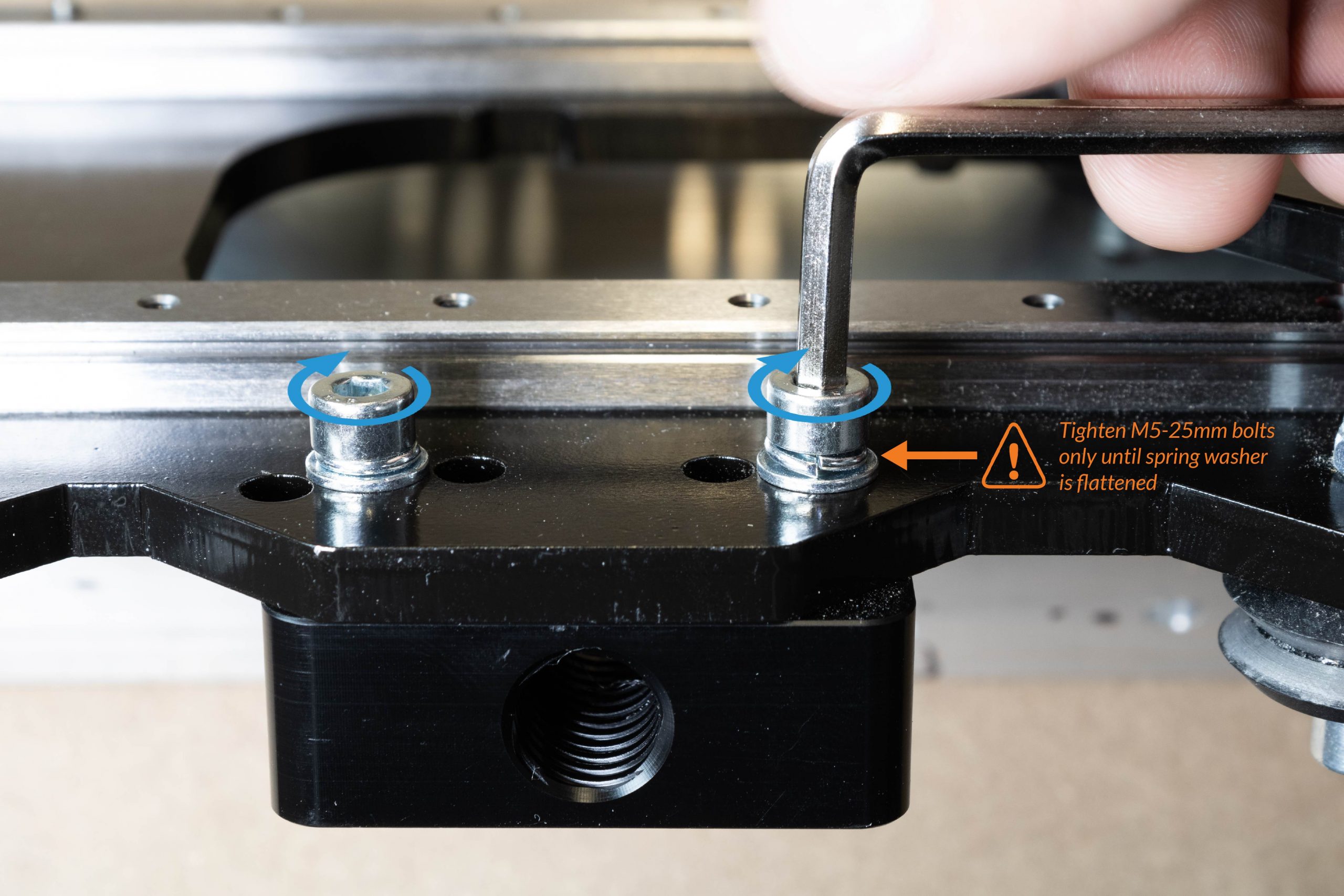
Tighten these screws only until the spring lock washer has been flattened on the two M5-25mm bolts. These should only be snug as over-tightening will not allow the Delrin nut to self-align and may bind up later on.
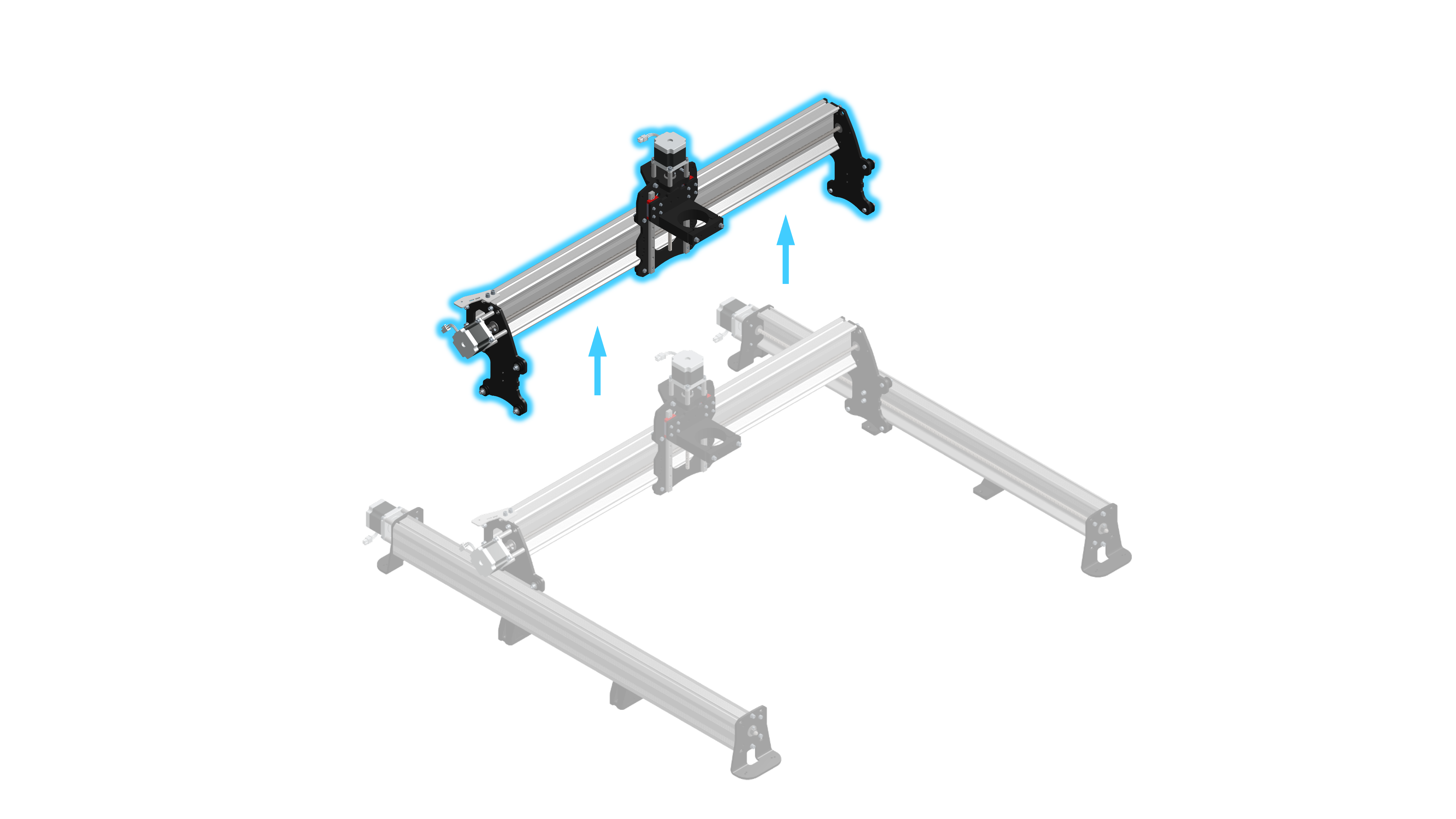
EX X-axis rail mounting
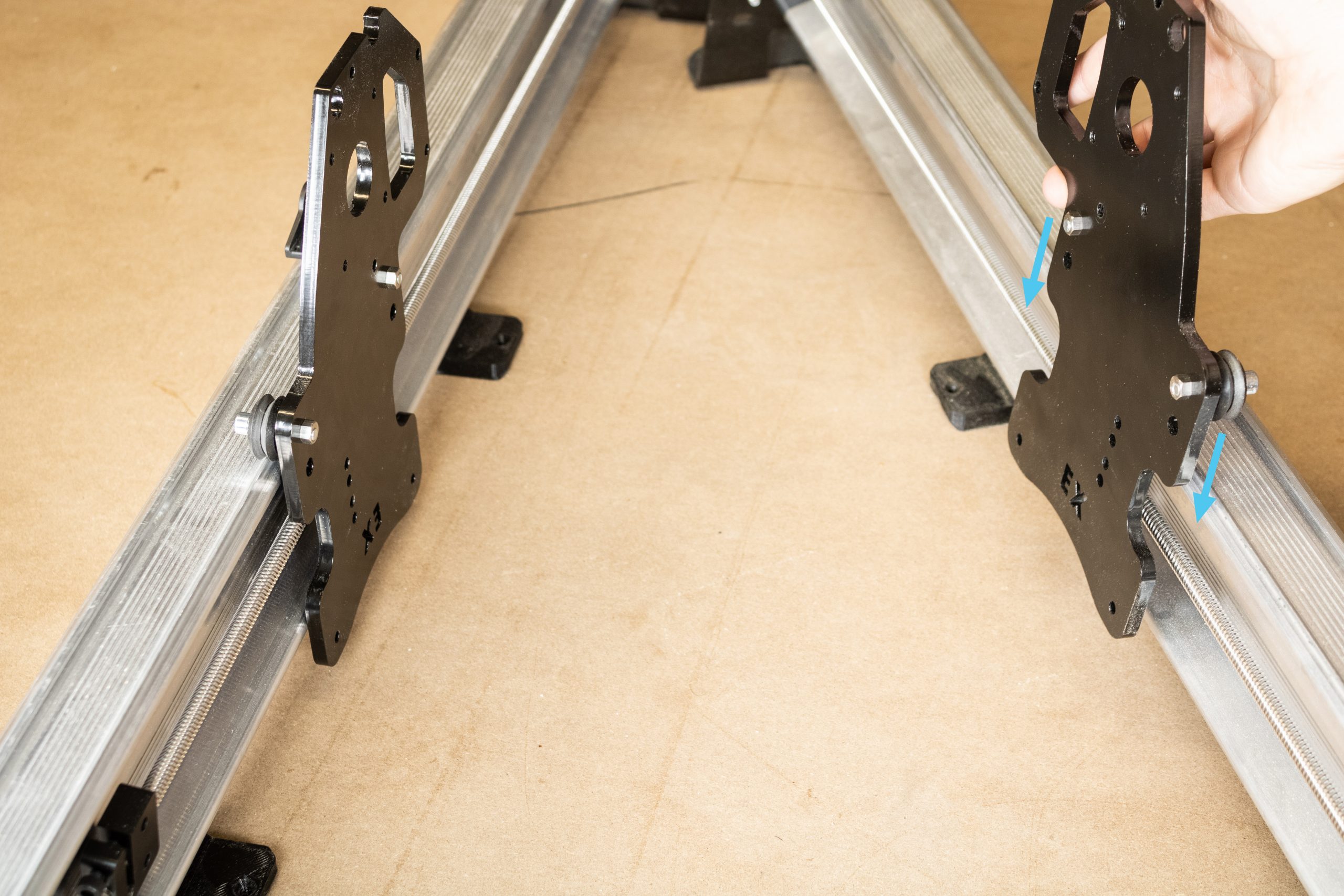
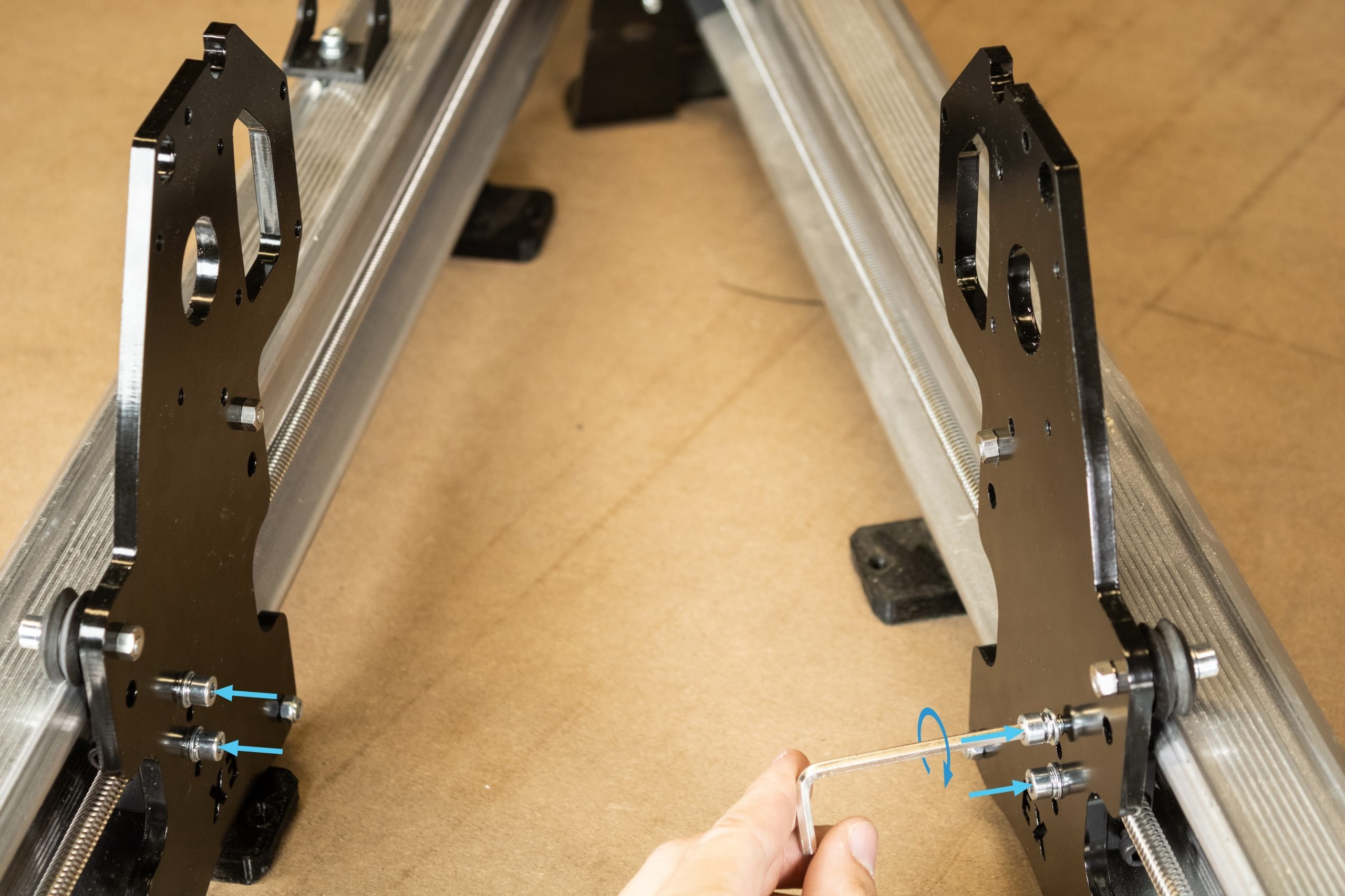
Attach the X-axis rail to the right Y-axis gantry plate using the four M5-25mm bolts.
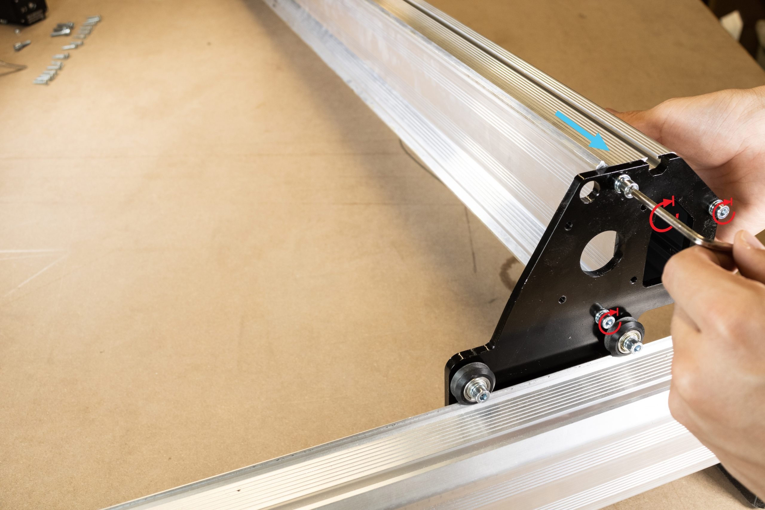
Lift up the left side of the X-axis rail and begin sliding the XZ gantry onto the rail.
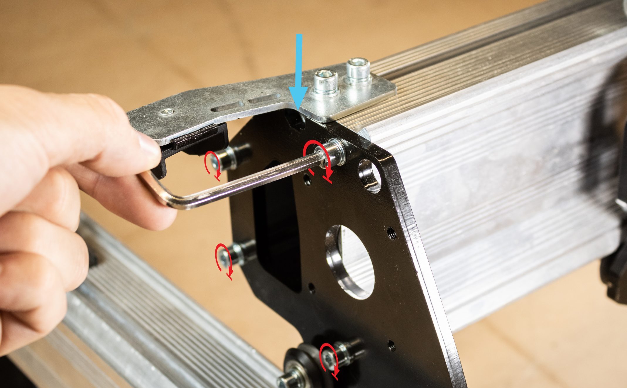
Lift the left side of the rail upwards and rest the drag chain mount on the left Y-gantry plate. Fasten the left Y-gantry plate onto the X-rail using four M5-25mm bolts.
X-axis motor mounting
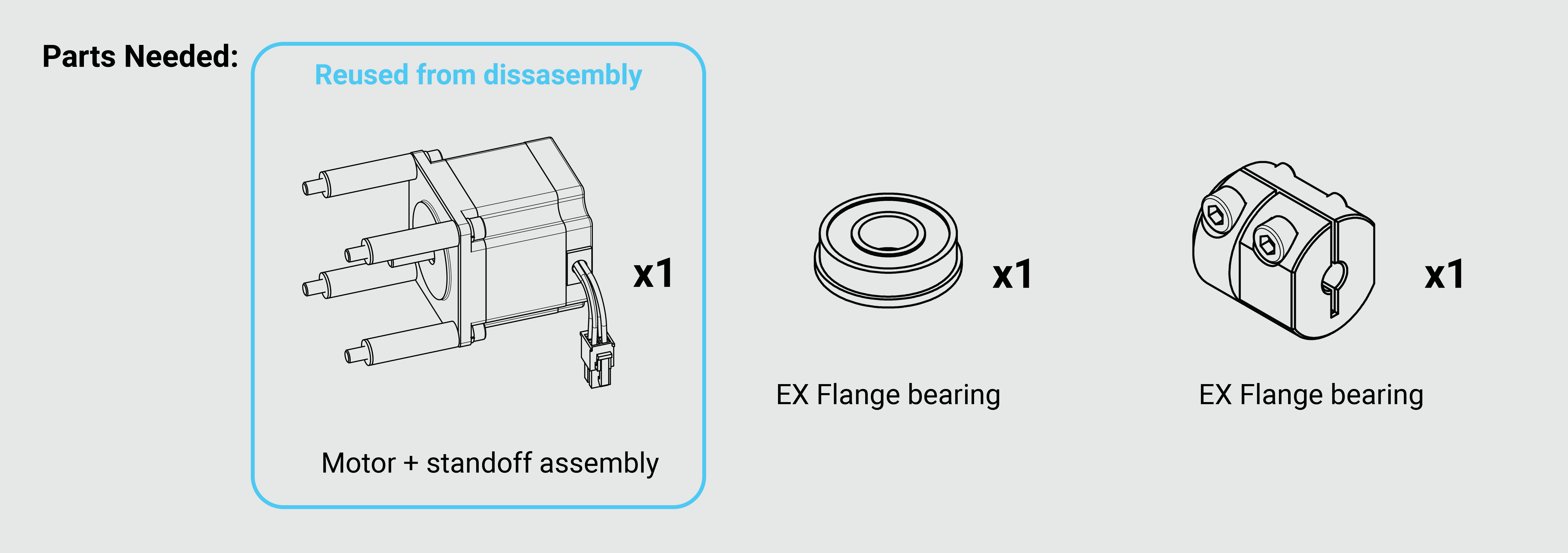
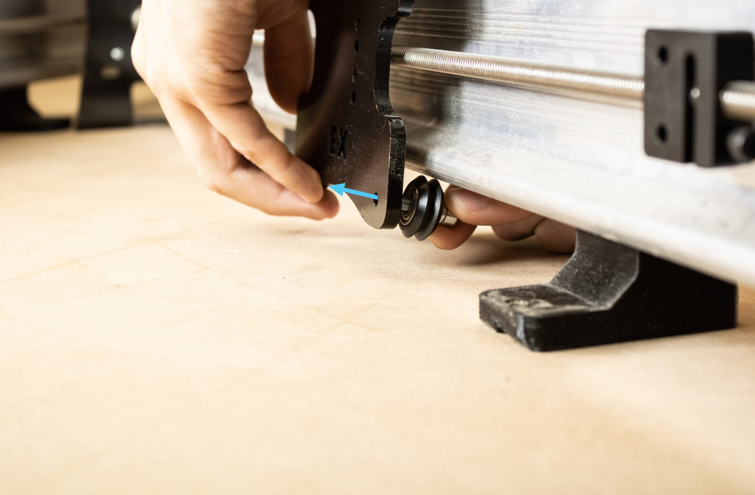
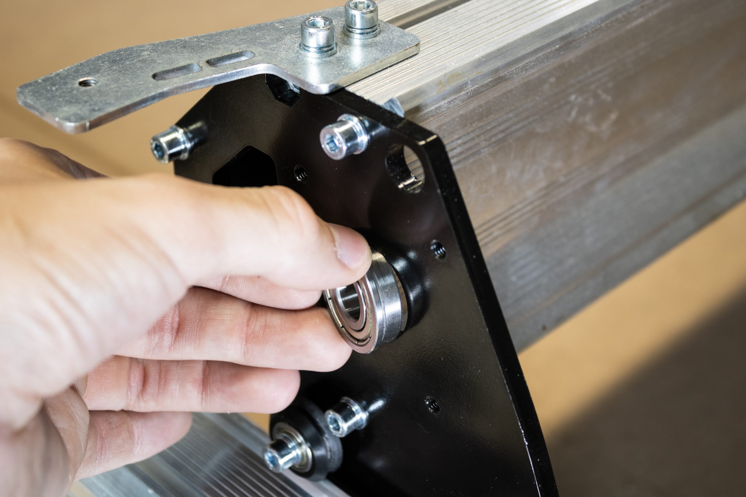
Slide a flange bearing into the left Y-gantry plate.
Grab the X-axis stepper motor assembly that was previously removed during disassembly. Slide the large EX coupler over the motor shaft. Do not tighten the bolts on the coupler, this will be left loose until the lead screw is installed.
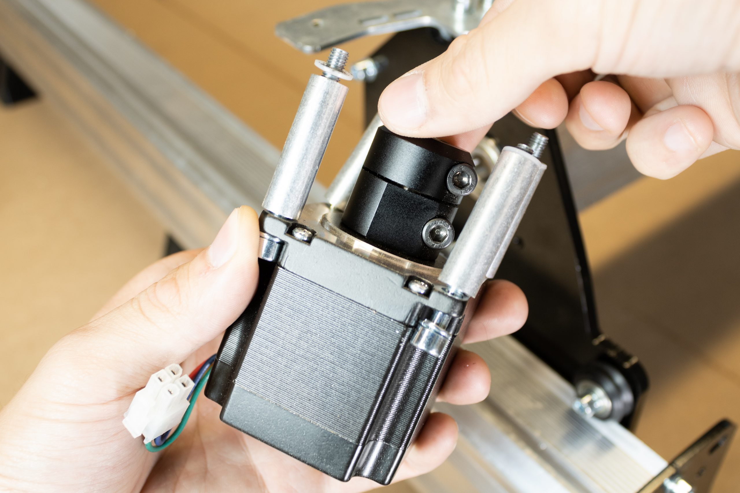
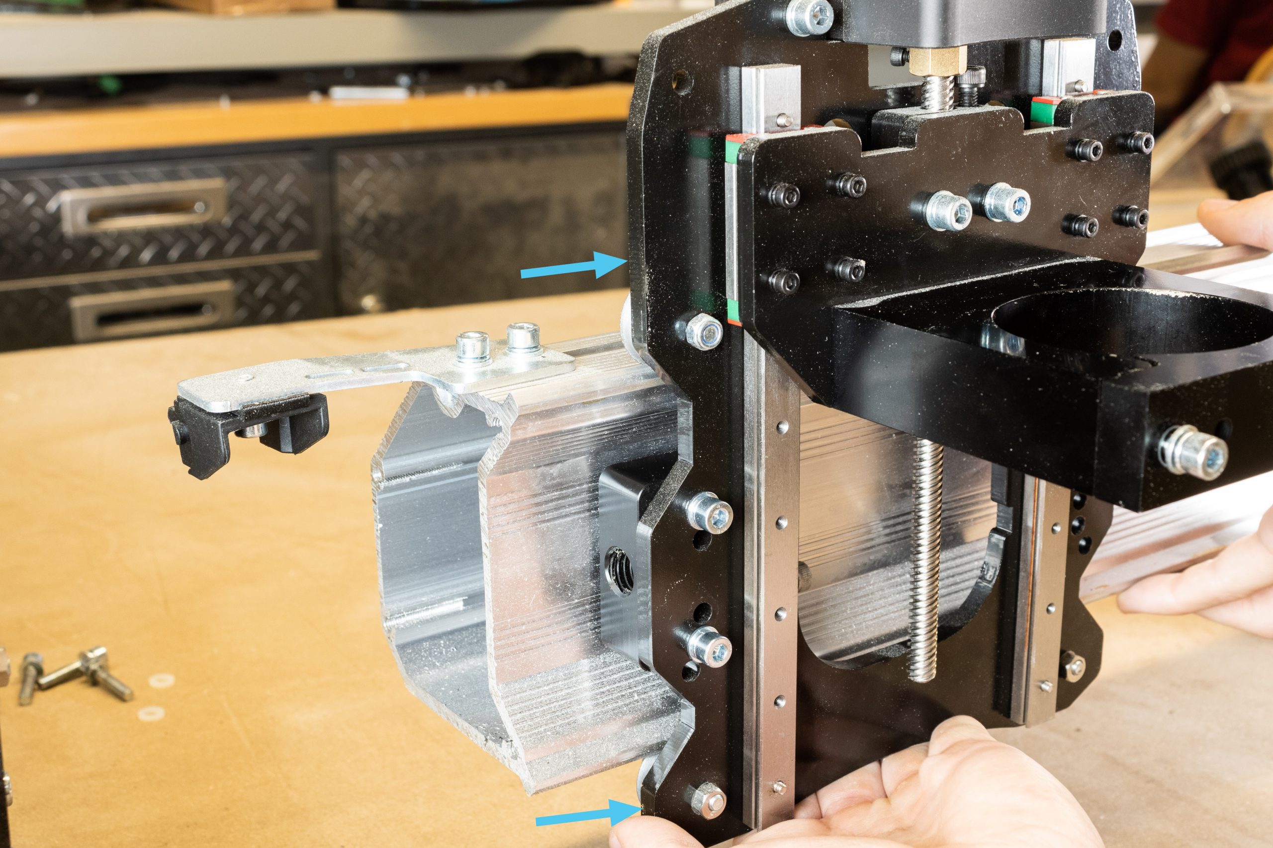
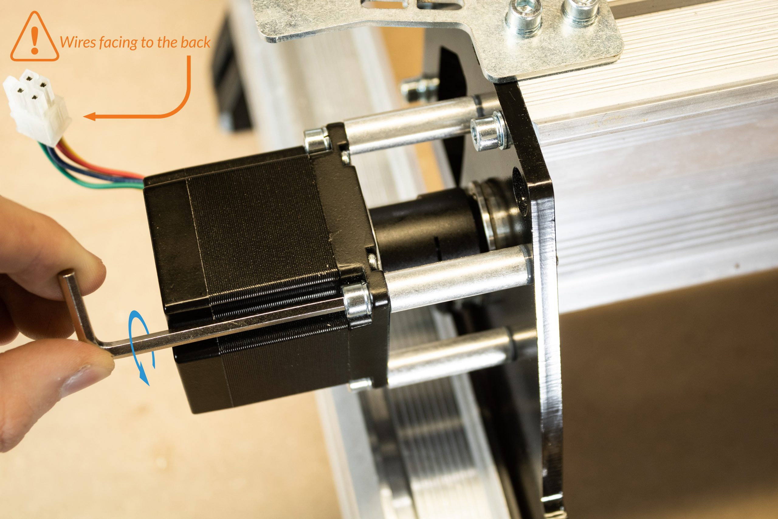
Mount this assembly onto the left Y-gantry plate, keeping the flange bearing in place. Orient the motor so the wires are facing towards the rear of the machine.
X-axis lead screw installation
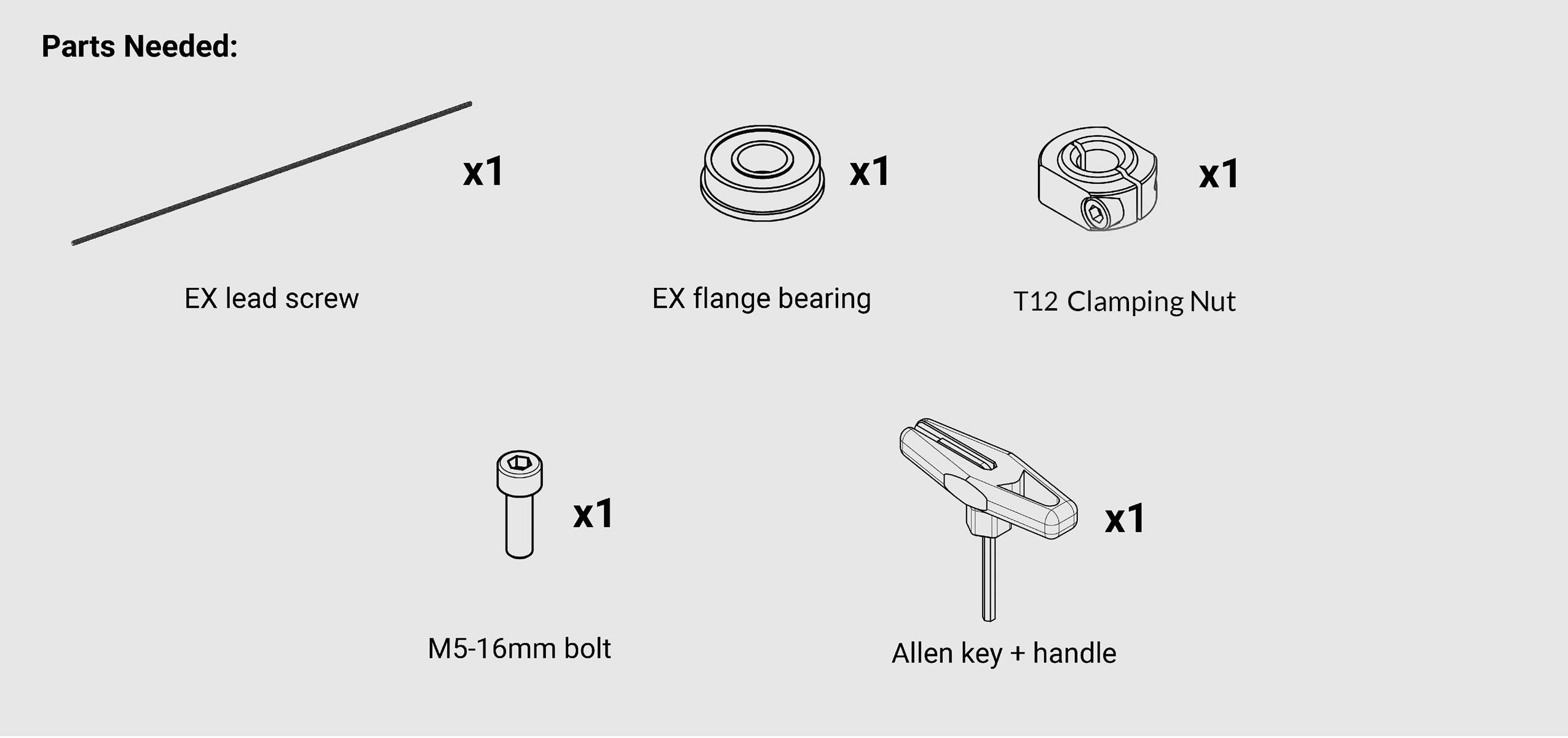
From the EX hardware box, grab the longer EX lead screw, as well as the second EX flange bearing, T12 Clamping nut with M5-16mm bolt, and Allen key + standoff assembly.
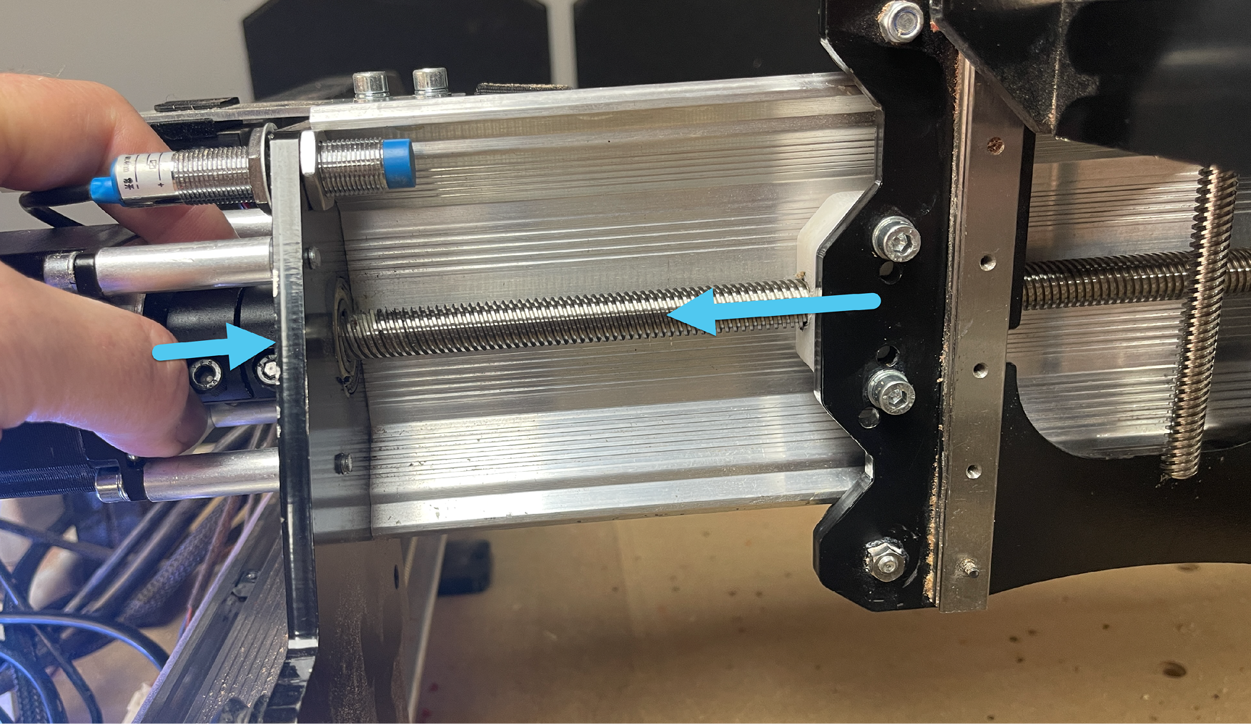
Pass the EX lead screw through the right Y-gantry plate towards the XZ-gantry assembly. Be careful not to bend the lead screw while doing this or handling it otherwise.
Begin threading the lead screw into the X-axis T12 anti-backlash nut.
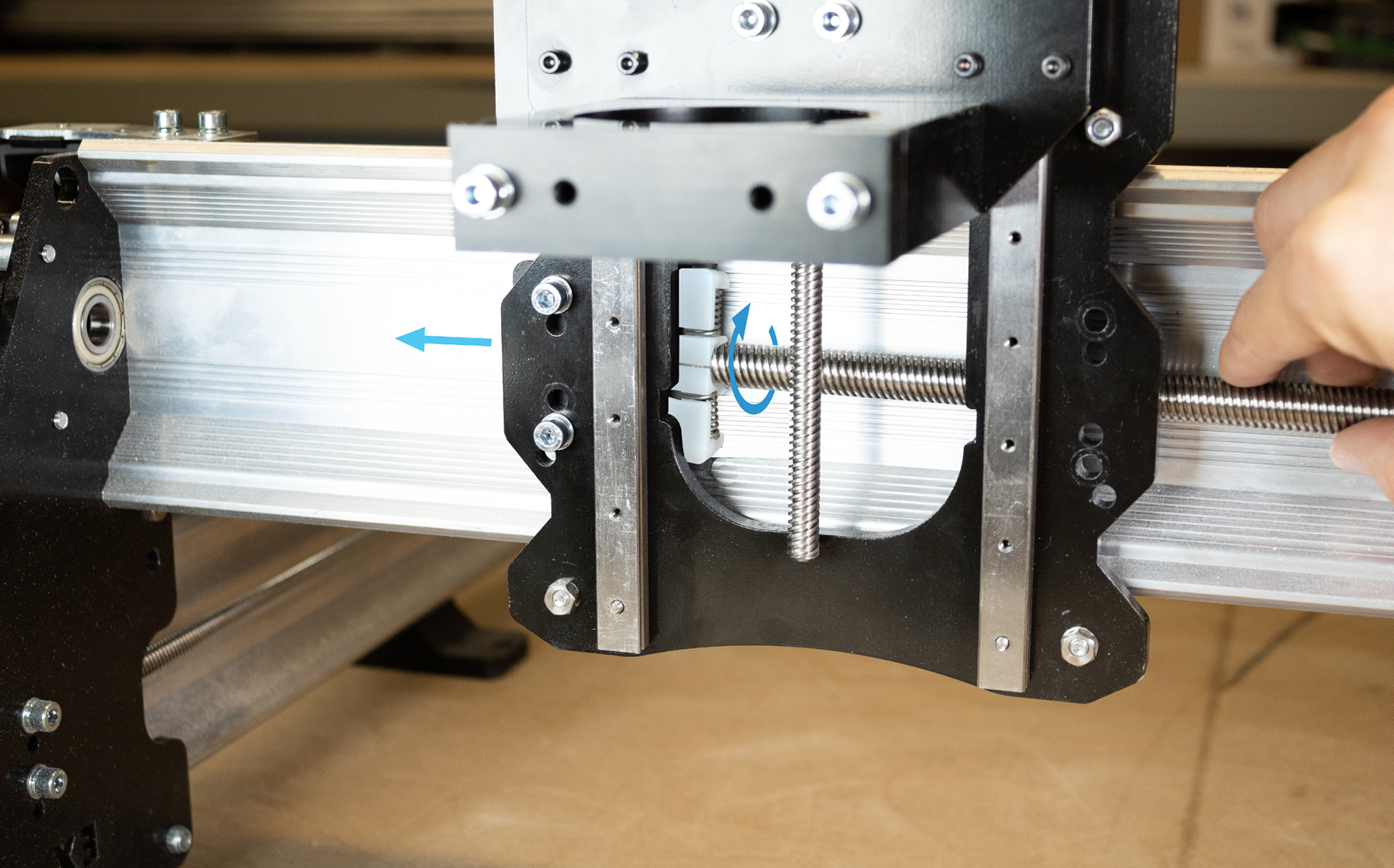
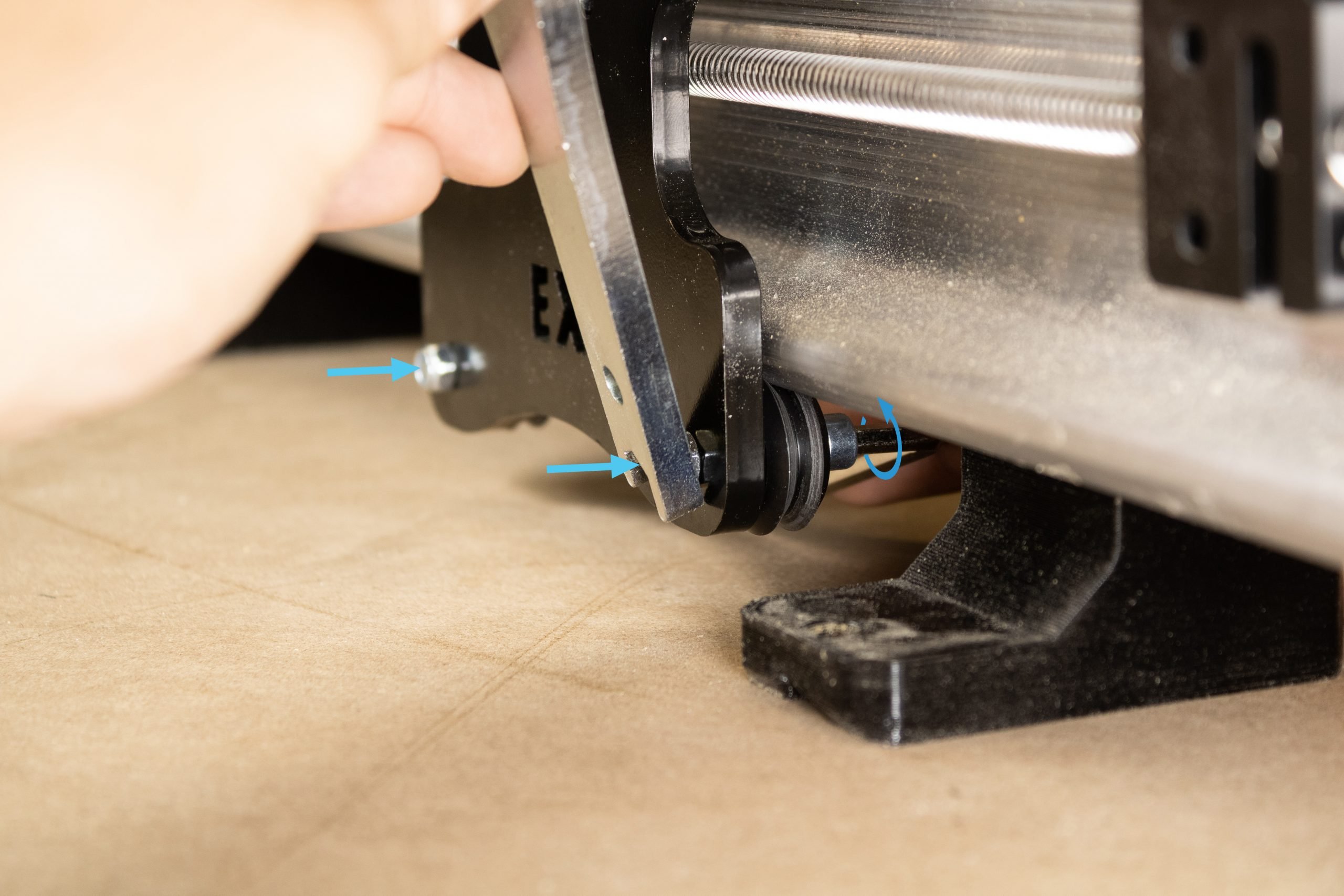
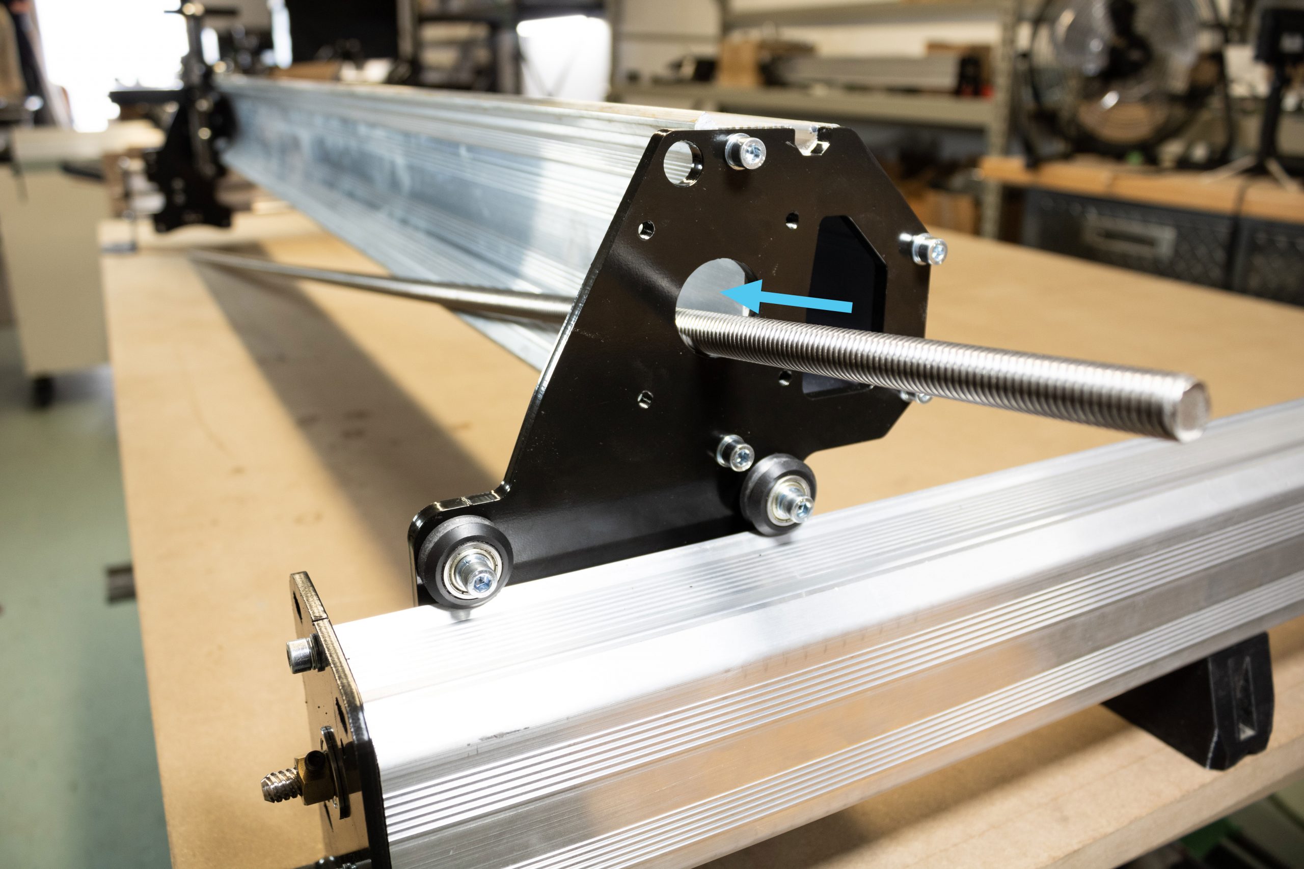
Continue threading the lead screw until it sticks out from the left side of the X-axis gantry. Slide the lead screw and X-axis gantry towards the left and pass the end of the lead screw into the flange bearing and into the motor coupler.
Push the coupler towards the right, and the X-gantry towards the left to ensure the lead screw is seated properly inside the coupler.
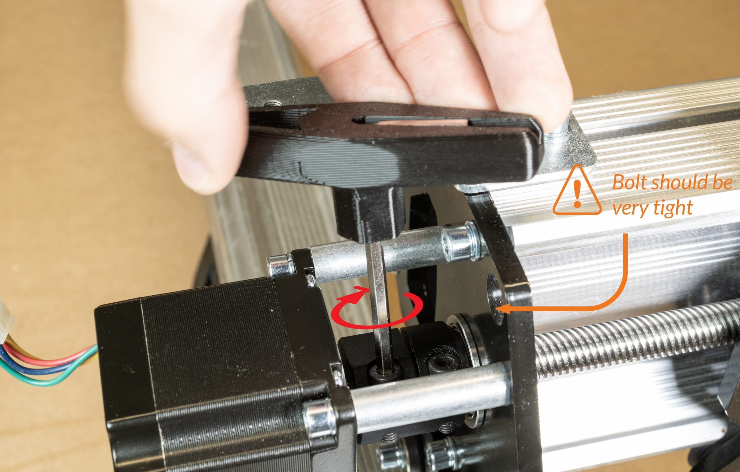
Tighten the motor coupler onto the lead screw. Use the Allen key + handle to do this as this bolt must be very tight.
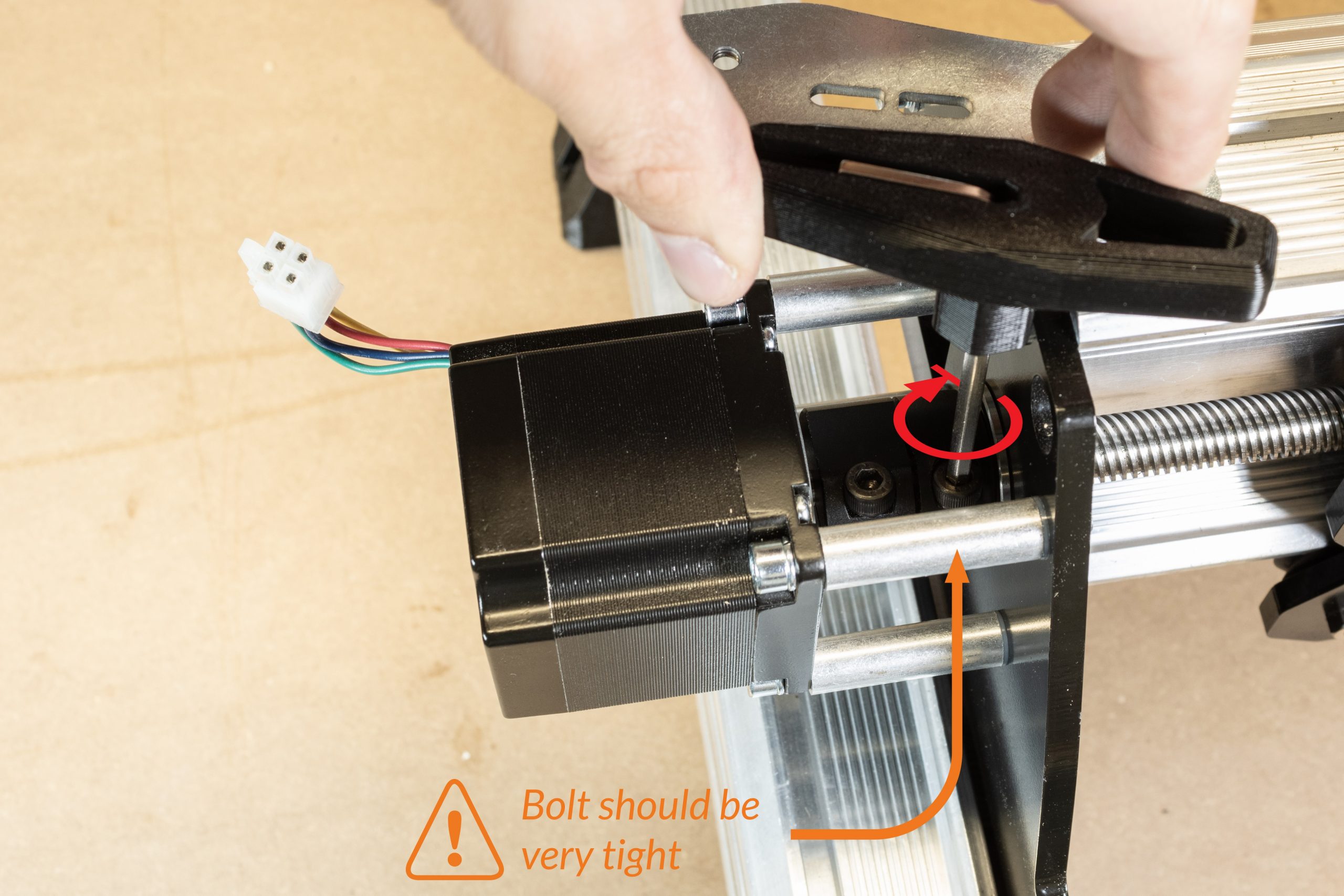
Remove the bolt from the other end of the coupler completely.
Pass an Allen key through this hole of the removed bolt to lock the coupler against the motor standoffs from rotating. Alternatively, a small screwdriver, bolt, or rod can be passed through instead. Locking the lead screw from rotating will allow for easier installation of the T12 clamping nut at the opposite side.
At the opposite side of the lead screw on the right Y-gantry plate, slide a flange bearing over the lead screw and into the Y-gantry plate.
Grab the T12 Clamping nut and begin threading this onto the lead screw.
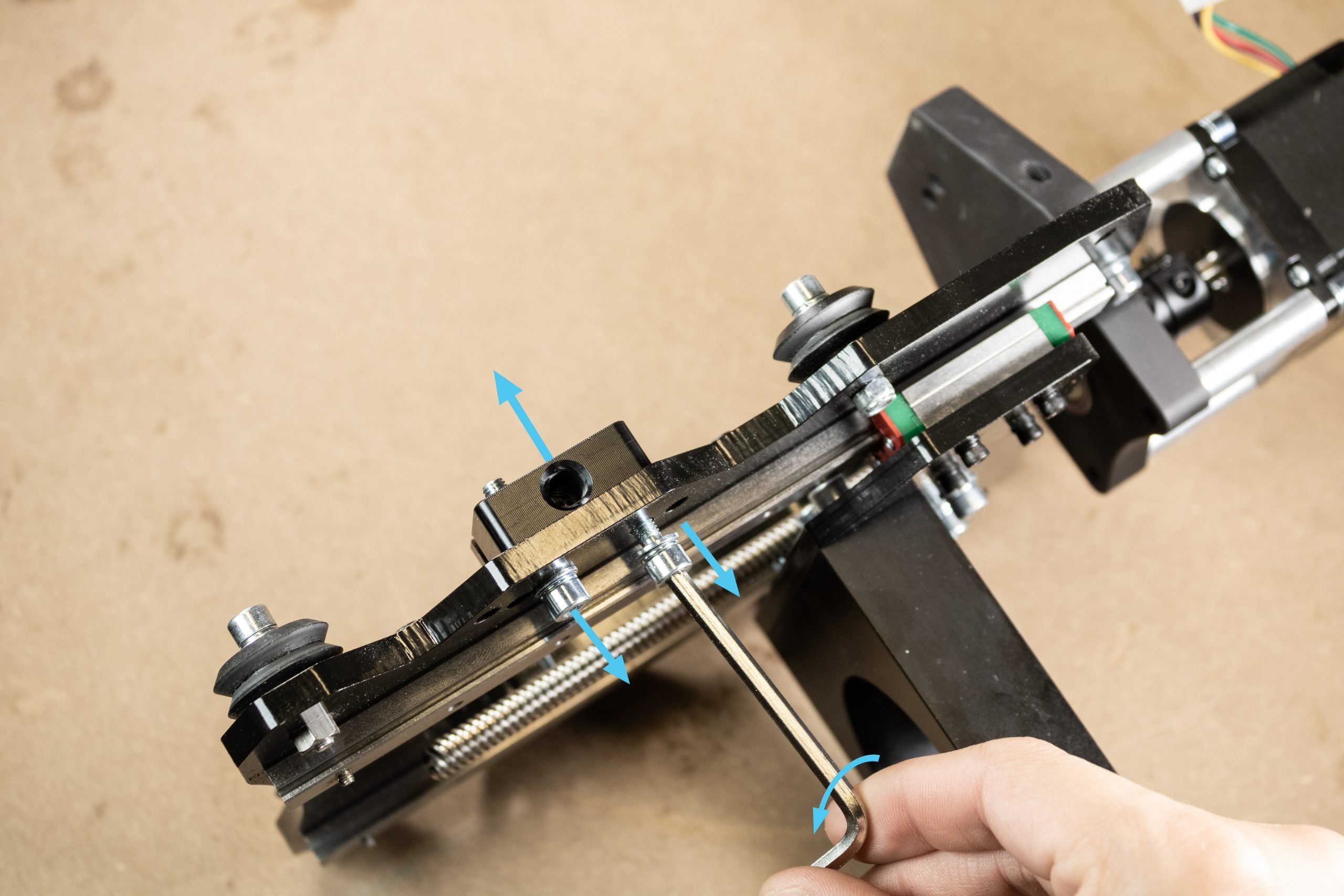
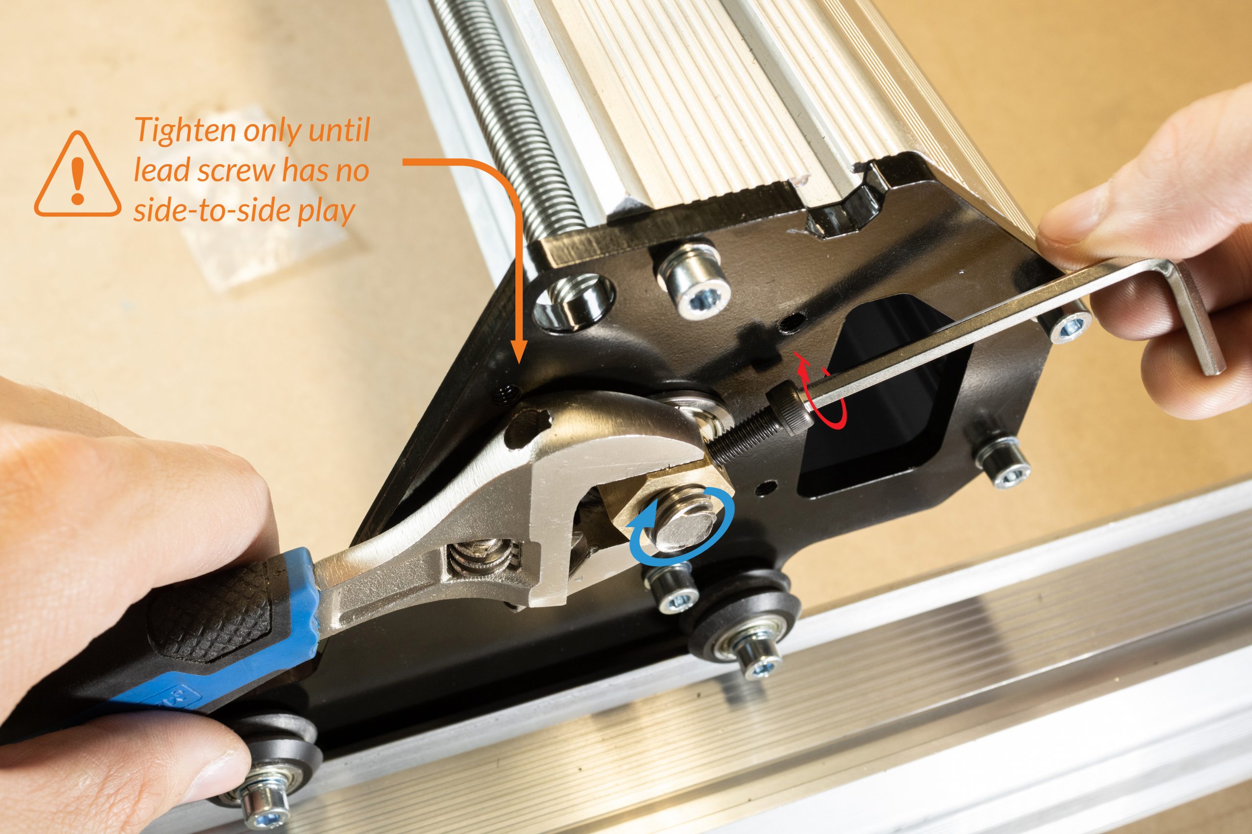
Using a 19mm, 3/4″ , or adjustable wrench, tighten this T12 Clamping nut only until the lead screw no longer has any side-to-side play. Then tighten the M5 locking bolt into the T12 locking nut to secure this.
Turn the lead screw by hand afterwards to make sure it spins freely. If you feel any significant resistance, undo the M5 locking bolt and loosen the T12 Clamping nut a small amount.
Remove any screwdrivers, Allen keys, or bolts from the coupler on the opposite side to allow the coupler and lead screw to freely rotate. Then reinstall the M5-16mm bolt into the motor side of the coupler and tighten this using the Allen key handle – this should be tightened very tight.
Drag chain and Wiring installation
Attaching drag chains
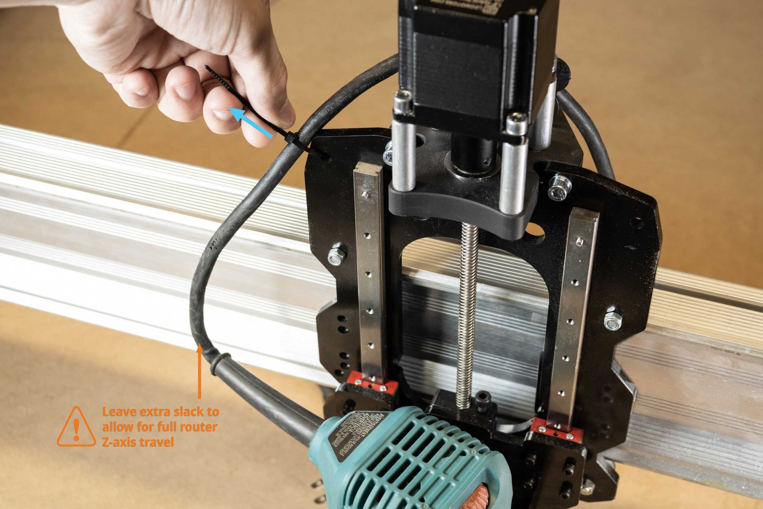
Reinstall your router into the router mount and optionally use the top left hole on the X-gantry as a zip tie point to keep your router wire out of the way during operation. If using a zip tie, ensure the cord has some extra slack to allow the router to travel all the way down during use.
Grab one of the two motor cables which were previously disconnected and connect it to the plug on the Z-axis NEMA 23 motor.
Connect the remaining motor cable to the plug on the X-axis NEMA 23 motor.
Grab the EX drag chain and position this running along the X-axis with the correct end of the drag chain oriented to clip on to the start and end links along the X-axis. Seat the Z-axis motor cable and router power cord into this drag chain.
Note: if you purchased the limit switch add-on kit, you’ll want to install the Z-axis limit switch and route this through the X-axis drag chain as well.
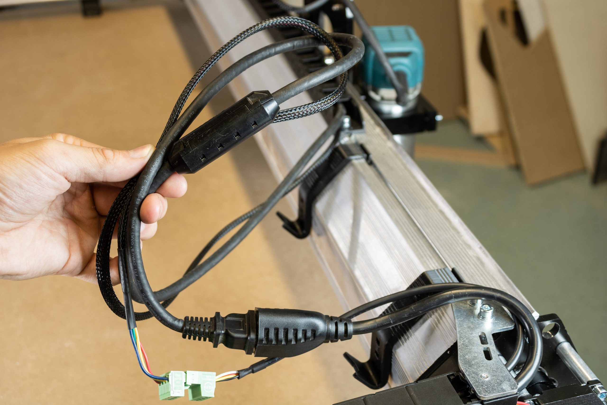
Grab the router power extension cable and motor extension cable from the EX drag chain & cable box in the X-axis rail box.
Connect the power extension and motor extension cables to the router power cord and Z-axis motor cable coming out from the X-axis drag chain. Connect the limit switch extension cable as well if applicable.
Note: if you purchased the limit switch add-on kit, grab the limit switch extension cable as well. Connect this extension cable to the Z-axis limit switch cable similar to the motor cable extension.
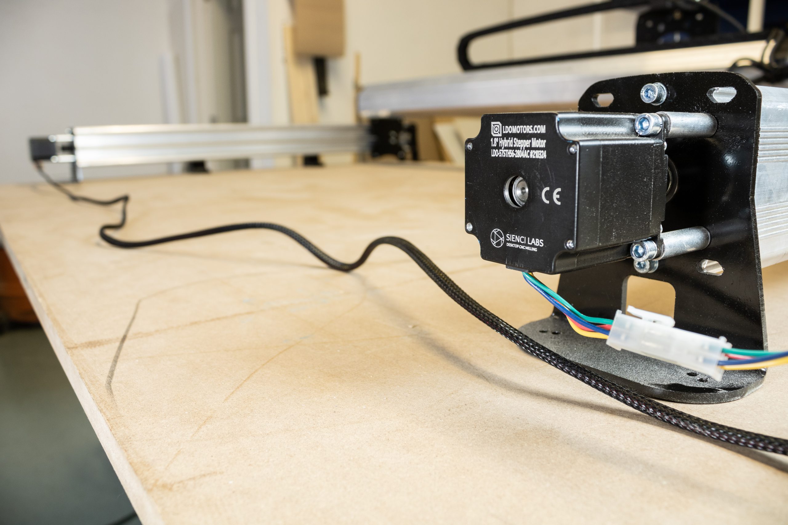
Grab a motor cable and connect it to the X-axis motor.
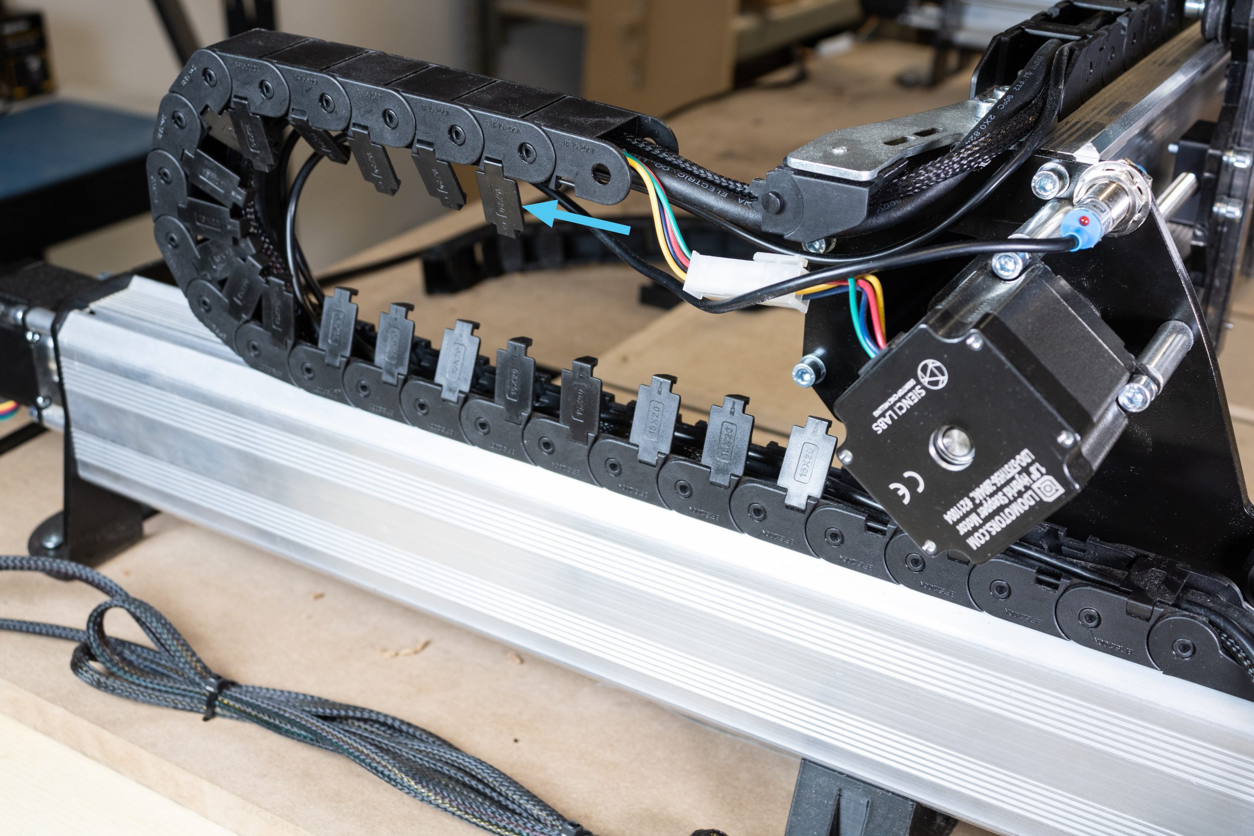
Begin routing these cables into the Y-axis drag chain, fitting these cables underneath the drag chain mount. Allow the connectors to sit outside of the Y-axis drag chain as shown. This excess bundling of cable will be organized neatly in the next step.
Secure the cables inside the drag chain by re-clipping each clip, then Attach the drag chain onto the start and end links mounted on the machine.
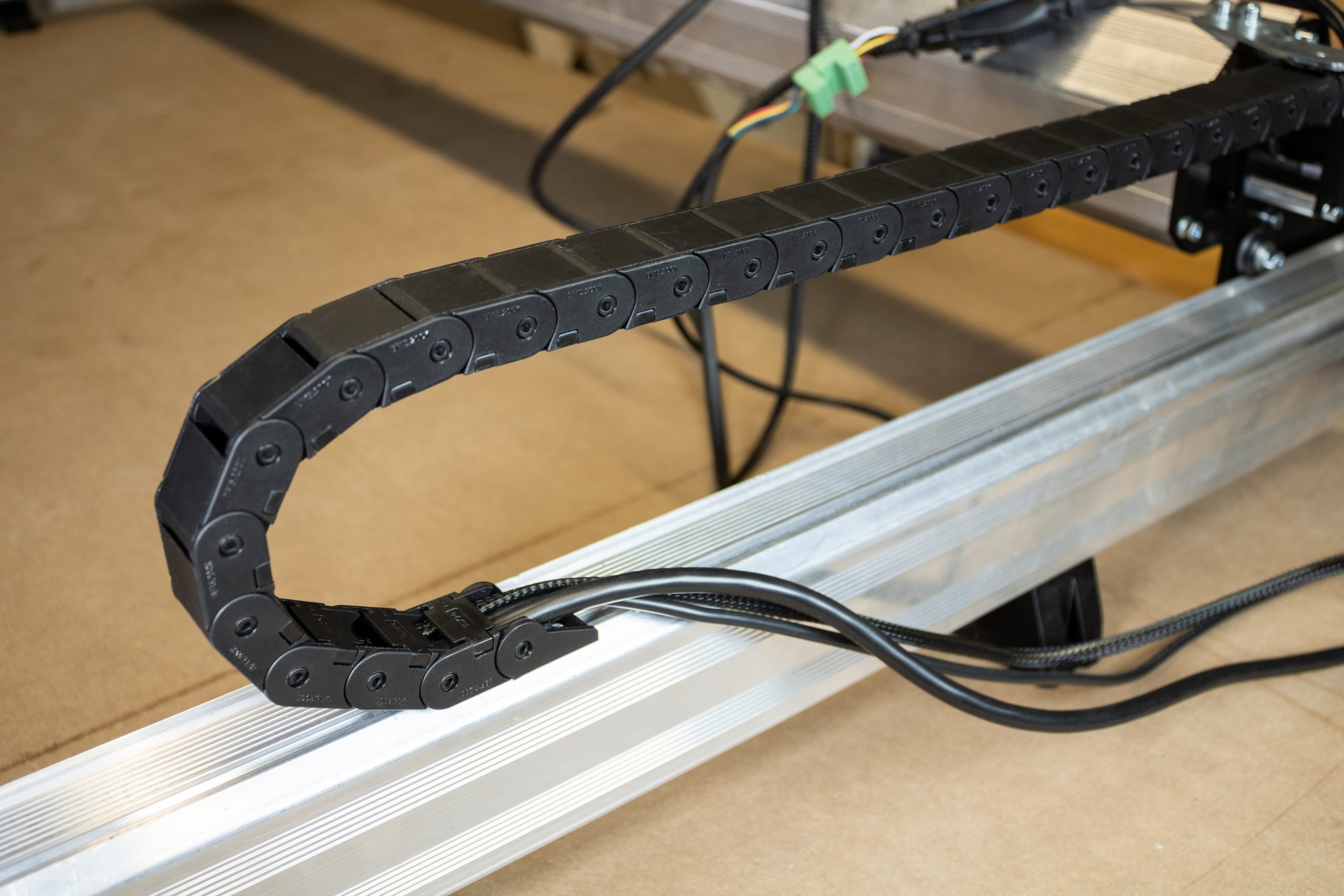
Organizing excess cable lengths
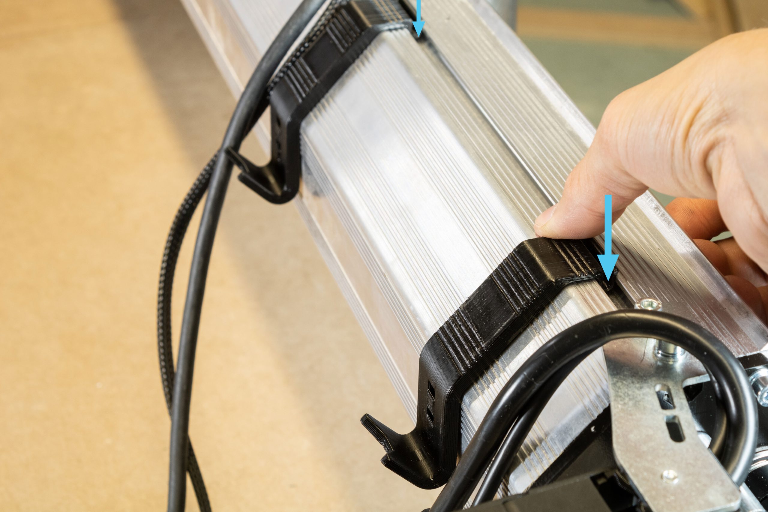
Grab the two ‘cable hangers’ from the EX hardware box. Align the clip portion of these into the T-slot on the X-rail and press directly downwards firmly to clip these in place. These are installed between the X-axis drag chain end link and the steel drag chain mount as shown.
Should you need to unclip these hangers for any minor adjustments, pull the bottom edge of the hanger upwards to rotate and unclip from the T-slot.
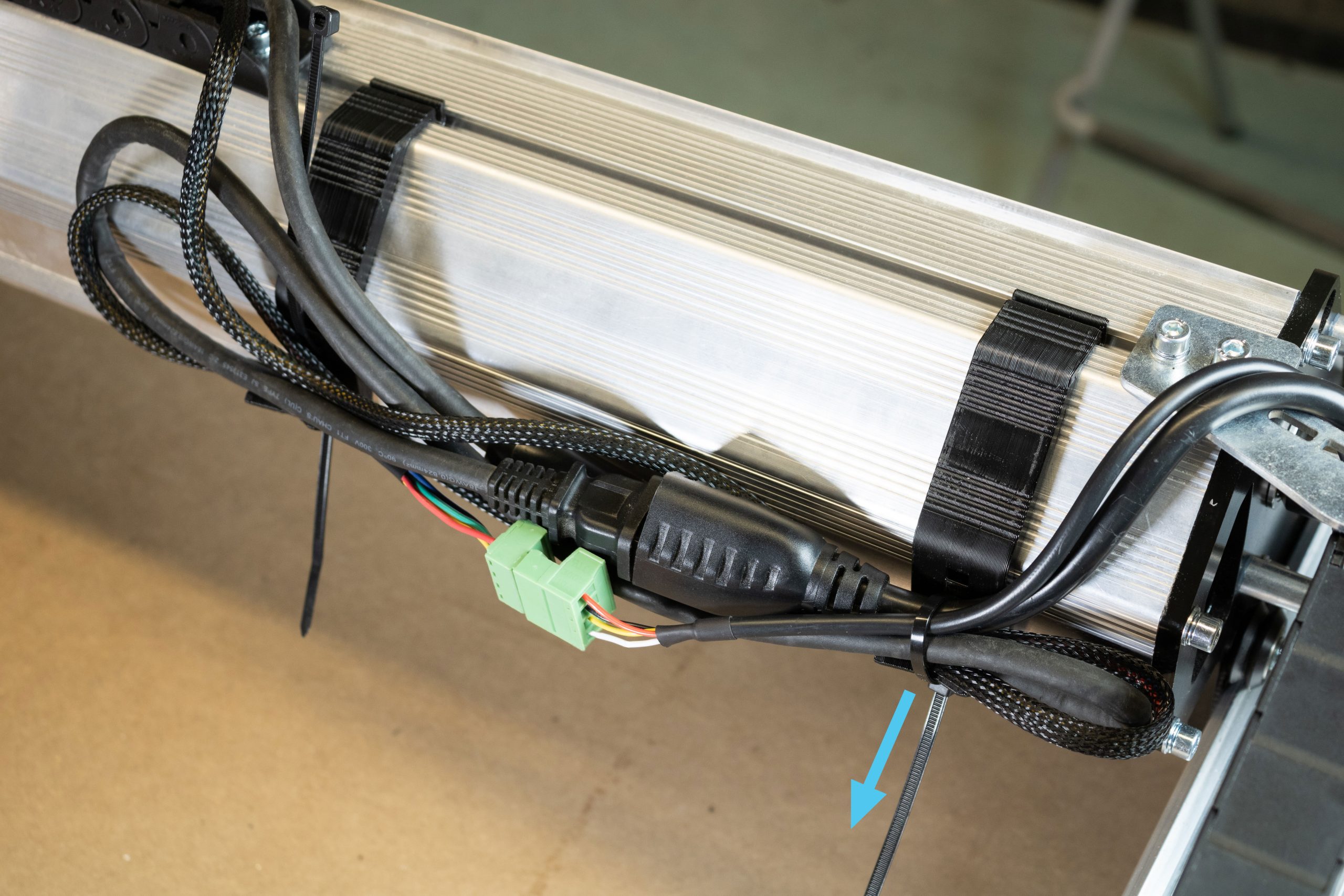
Get two zip ties from the X-axis EX hardware bag and insert these into the lower hole in each of the drag chain mounts.
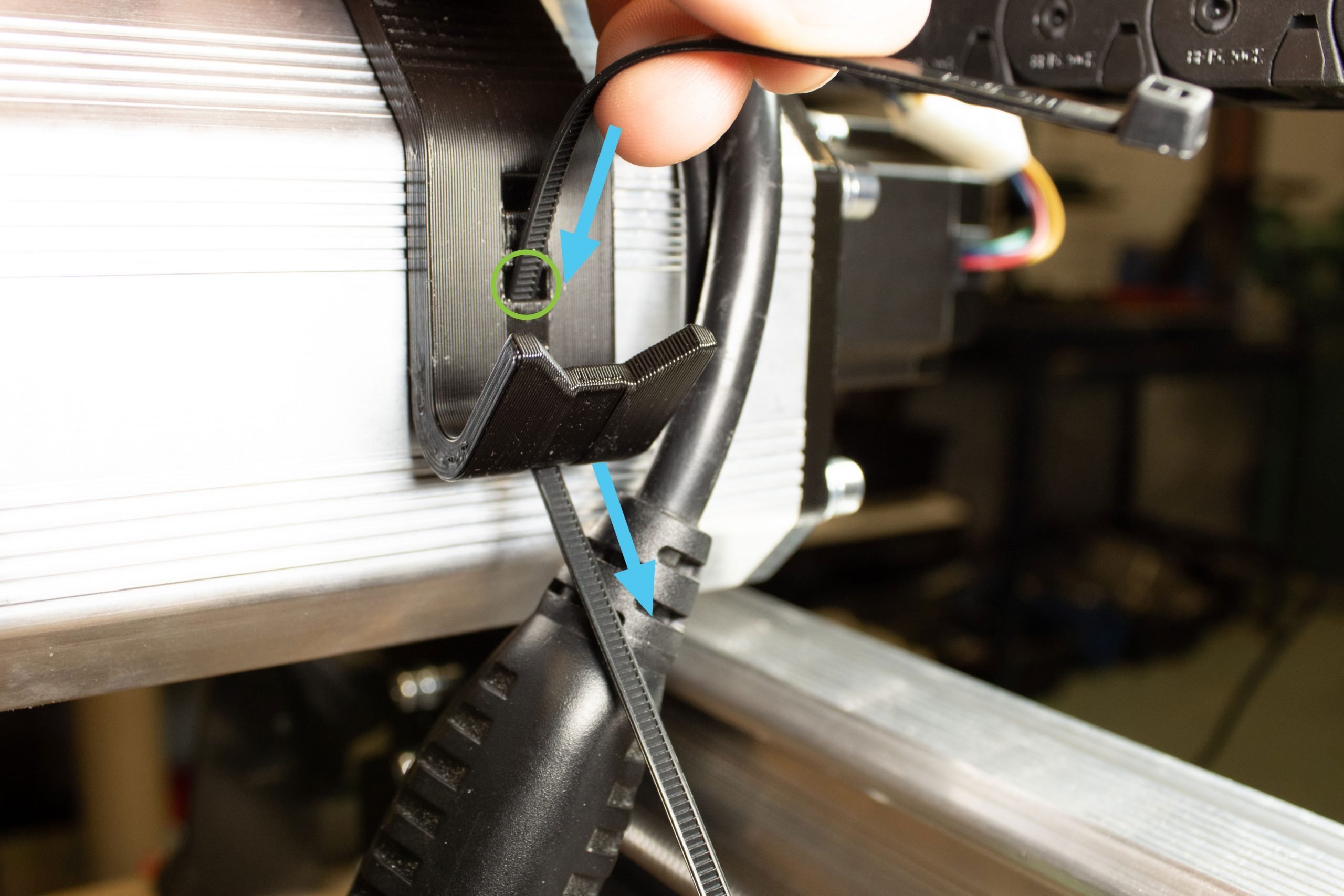
Straighten out the excess cabling into one bunch, then fold this in half.
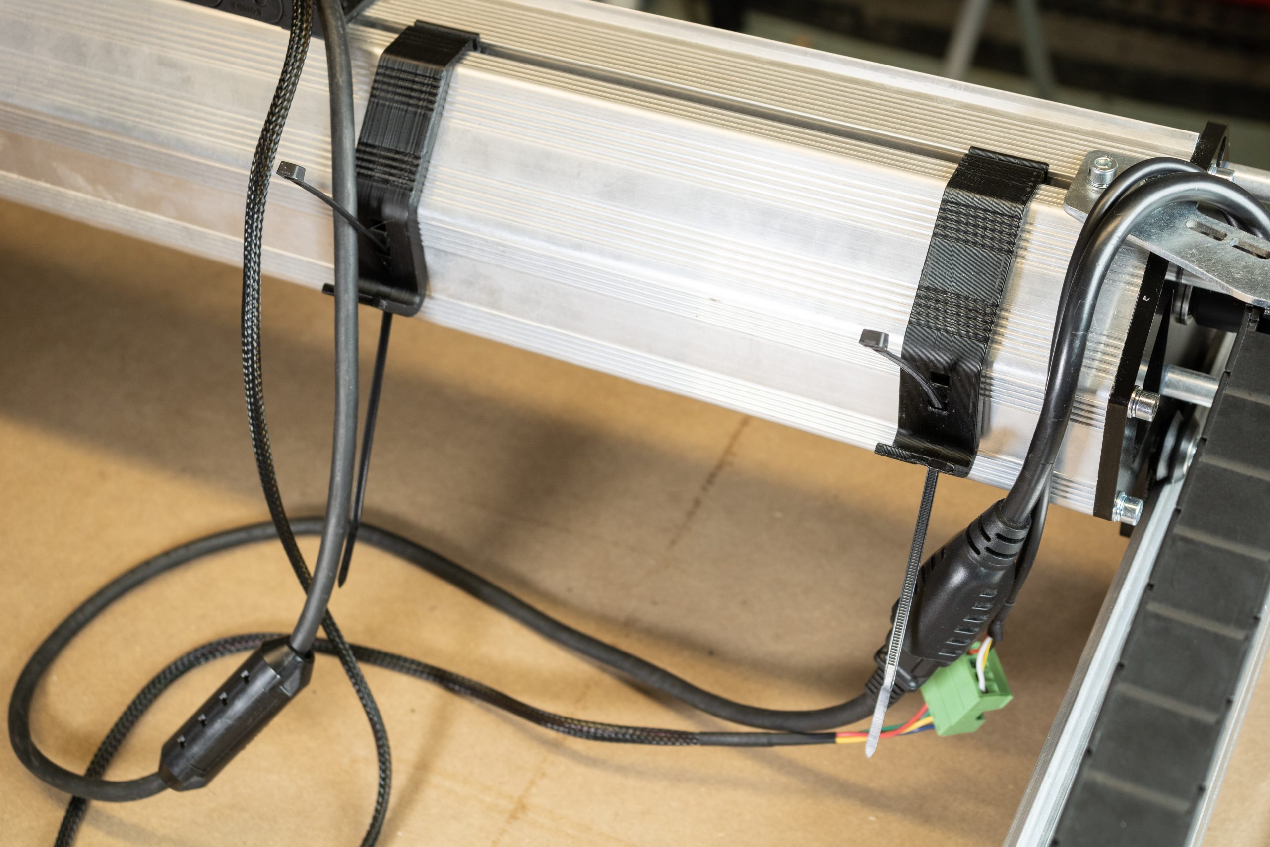
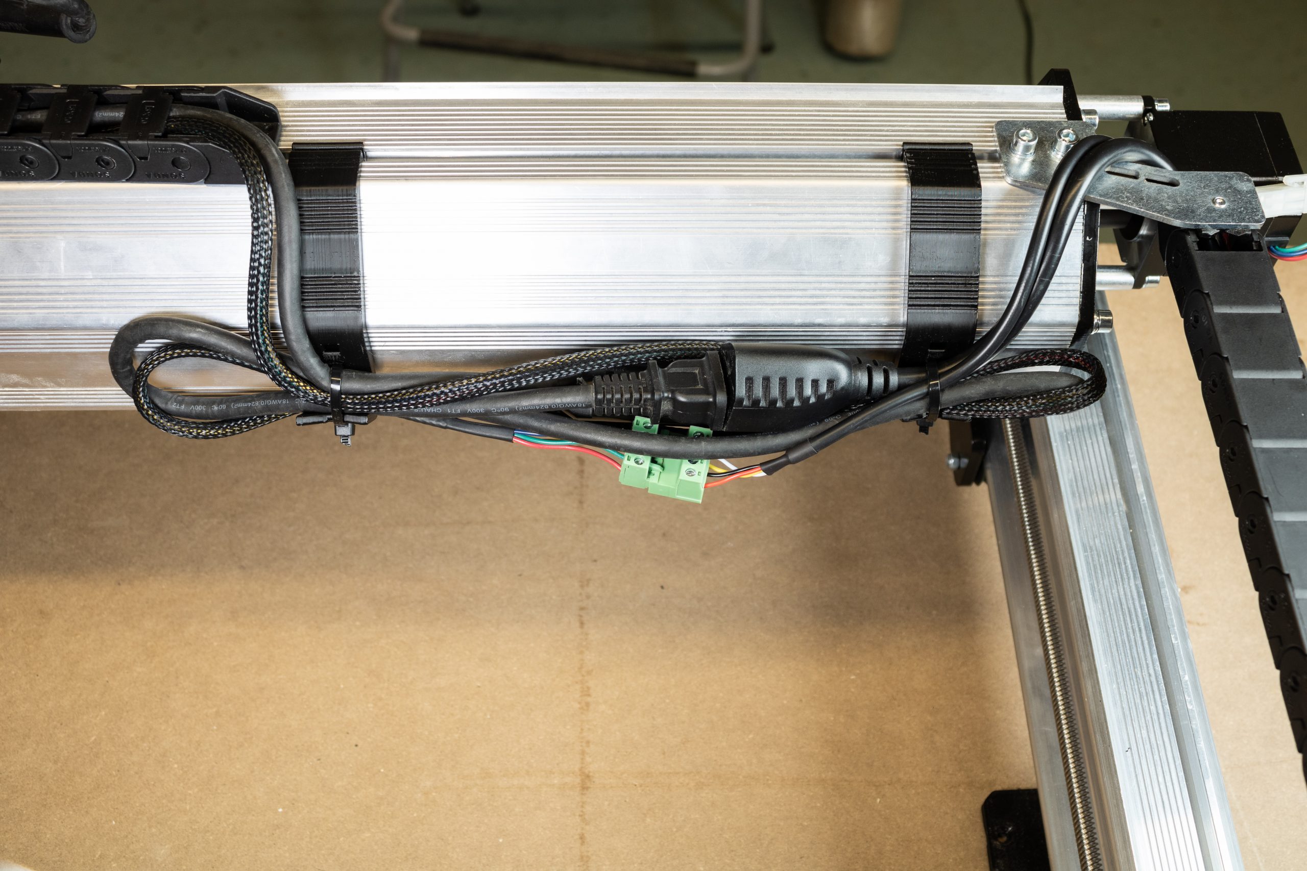
The folded bunch of excess cables can then be secured into both cable hangers. Tighten the two zip ties at each hanger. Trim the excess length from the zip ties once finished.
Adjust any of the cabling so it fits well within these two hangers and nothing hangs below the X-axis rail, then tighten the zip ties fully. You can adjust the position of the two cable hangers before tightening these zip ties for good. In any case, extra zip ties are provided just in case you’d like to come back and make any adjustments.
If you’ve unplugged the two cables for the Y-axis stepper motors, plug these back in now.
Bring the cables around to the left of the machine so they’re now all bundled together (pictured). You’ll be plugging the motors cables into the control box shortly but otherwise the machine wiring is now complete!
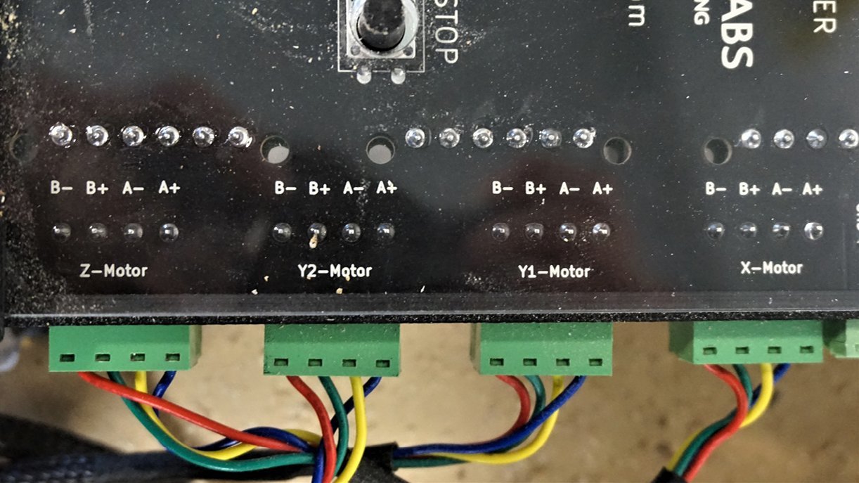
Reconnecting control box
Plug the X-axis motor cable, Z-axis motor cable extension, and the two Y-axis motor cables into the control box as shown. Re-connect any other cables which may have been disconnected during earlier disassembly.
Note: if you’ve installed a Z-axis limit switch and its respective extension cable, plug this into the Z-axis limit port.
Tuning Movement
Before the LongMill can be mounted onto the larger wasteboard, the V-wheels and Delrin nuts on the X and Y axes will need to be tuned to ensure the machine’s axes will all self-align when moved.
The steps outlined for the original LongMill MK2 tuning can be referenced for this here.
Table Mounting
With the X-axis now being extended to 48″ working capacity, your LongMill will of course need a much larger work surface now. The 48×30 LongMill MK2 will require a wasteboard that is 48″x70″. The outer dimensions of the 48×30 LongMill MK2 are shown in the diagram below.
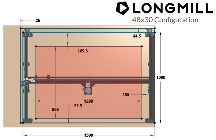
Despite the larger size, the table mounting process remains the same as the original 30×30 LongMill MK2. Follow the table mounting instructions for this found here.
Congratulations on finishing the installation of your LongMill MK2 48″ extension kit! While the operation of your LongMill will stay largely the same, we hope you can take advantage of the extra cutting real estate and benefits that come with the larger X-axis material capacity. Good luck and happy making!
-The Sienci Labs team