
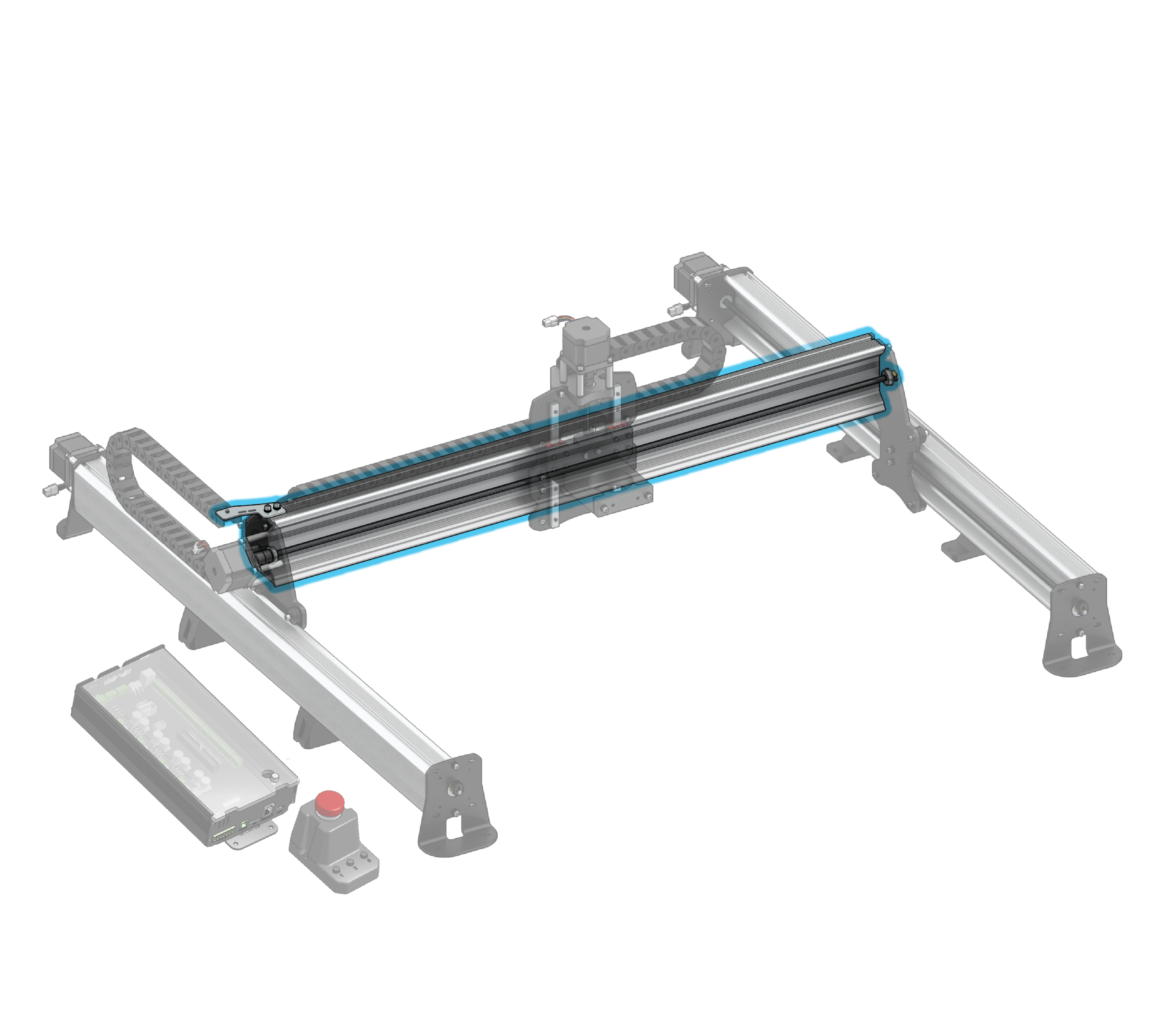
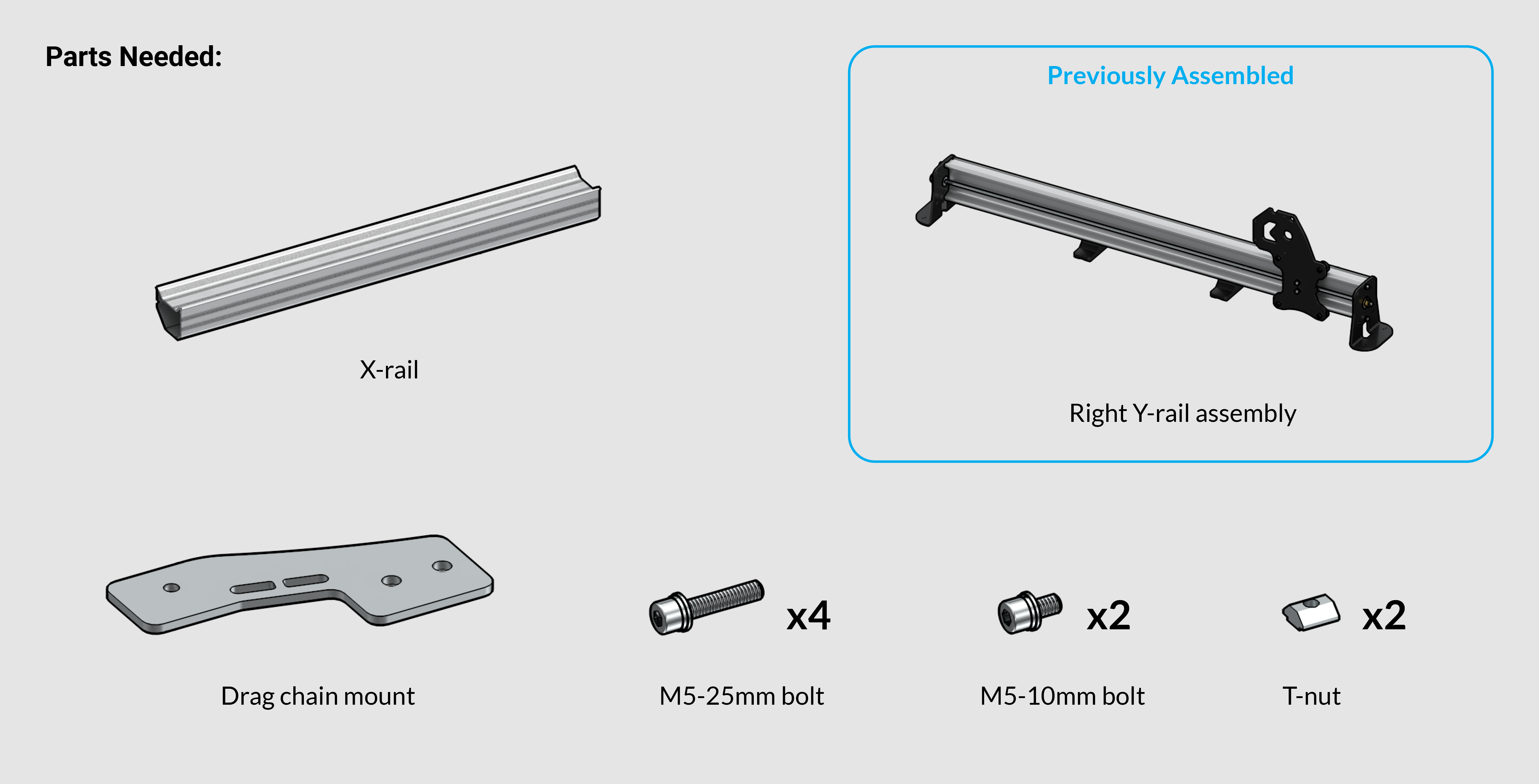
Drag Chain Mount and Connecting Rails
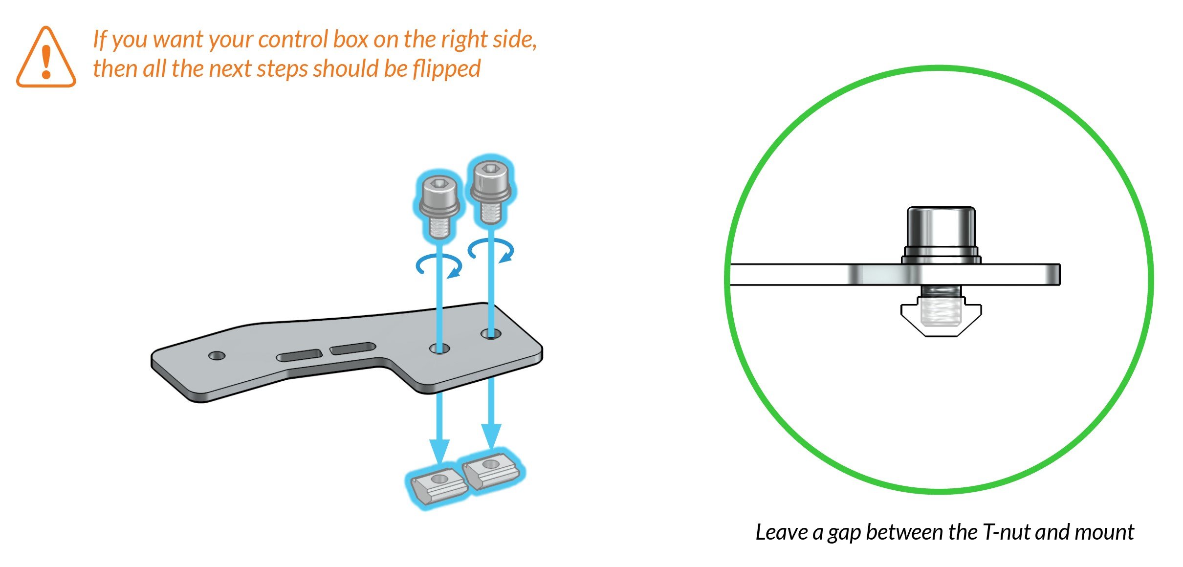
Grab the M5-10mm bolts, t-nuts, and steel drag chain mount from the yellow hardware bag. Prepare the drag chain mount by loosely threading two M5-10mm bolts into the two t-nuts.
Note: if you want your control box on the right side rather than the left then most of the remaining steps should be flipped including drag chain mount, subassembly steps, X-axis lead screw and motor, and drag chains.
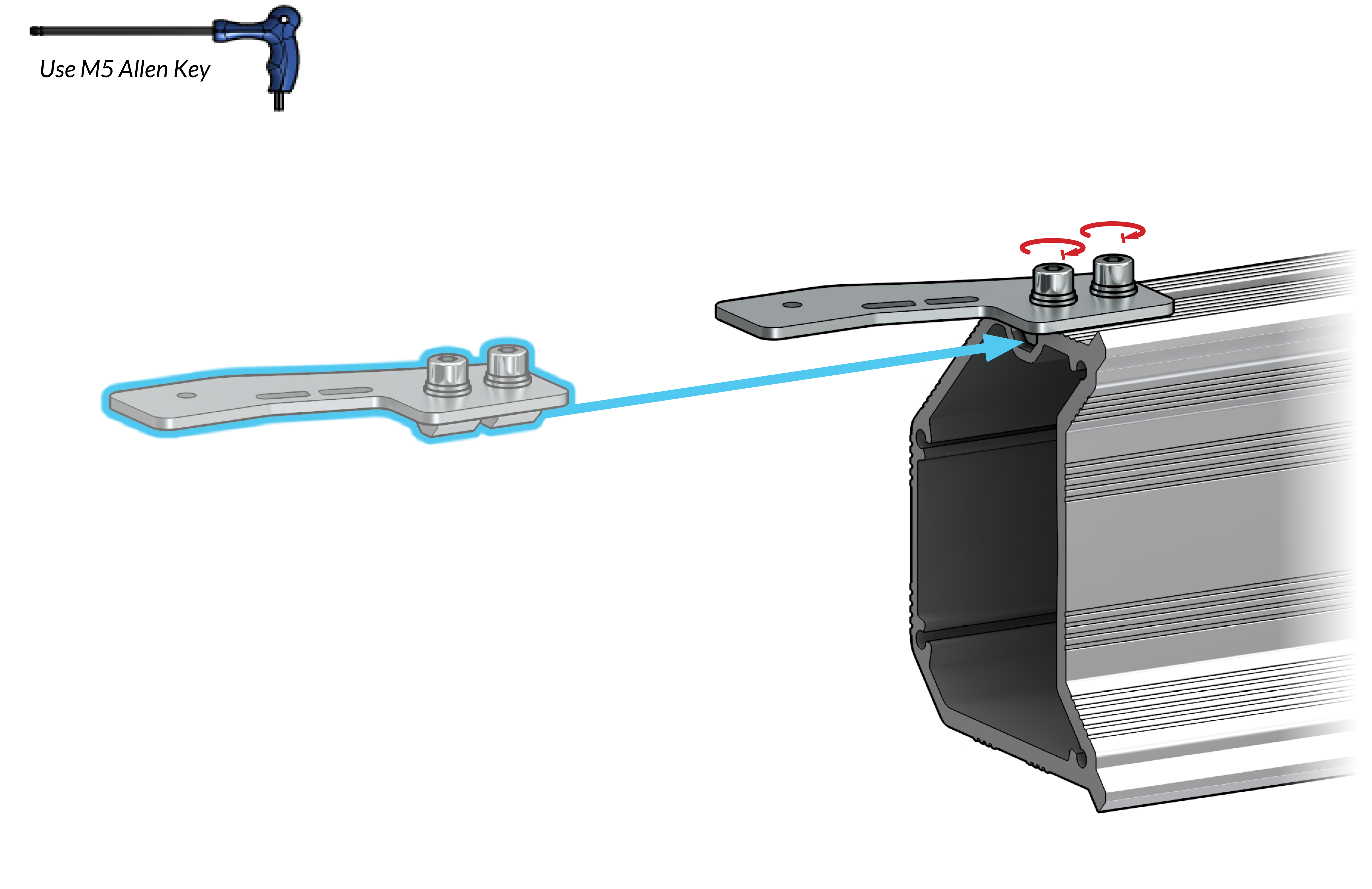
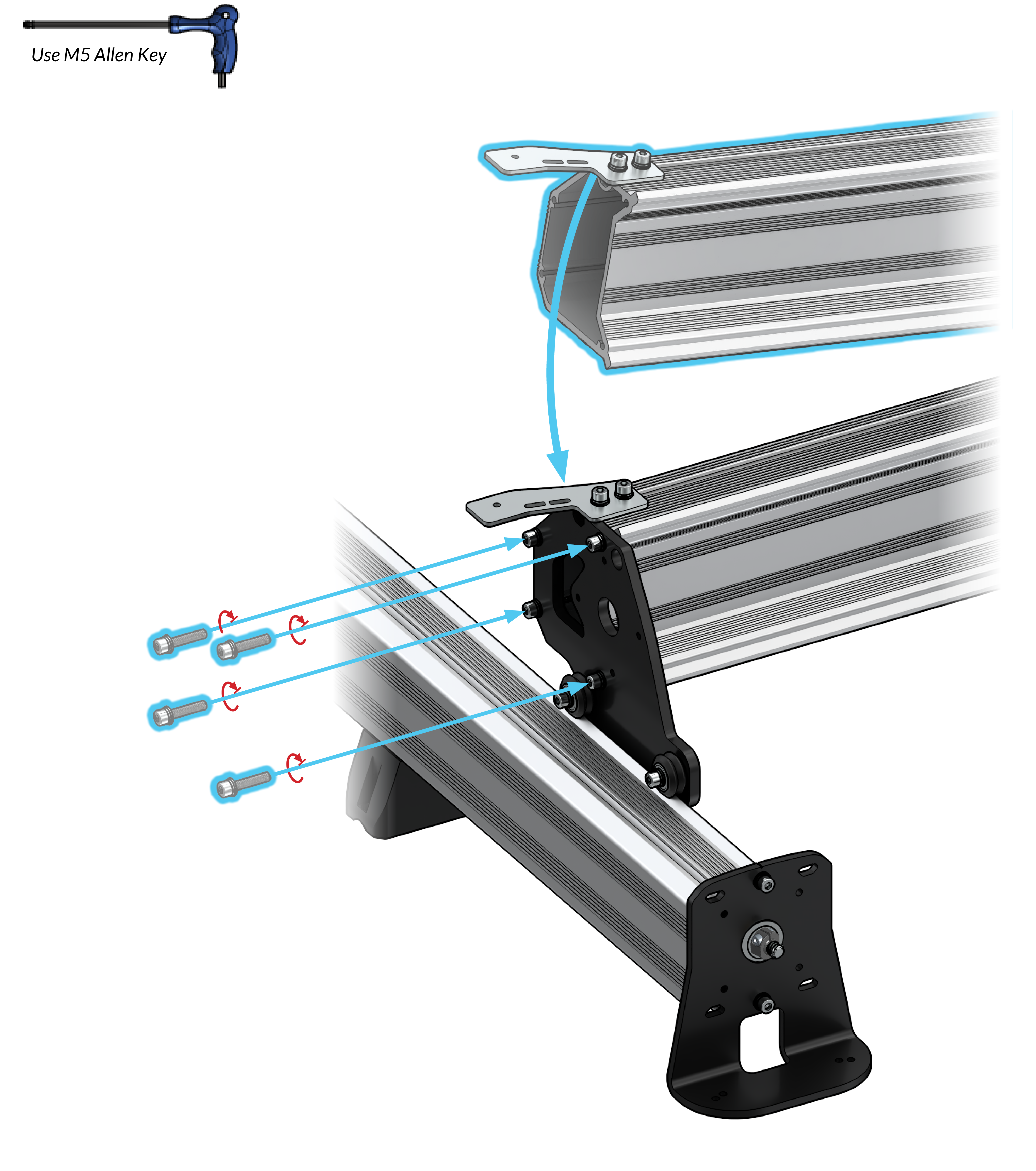
Attach the drag chain mount through the left side of the X-axis rail by sliding two t-nuts onto the top slot of the rail. Before fastening the drag chain mount, ensure that it is offset from the edge of the rail by about 6mm or ¼” (pictured).
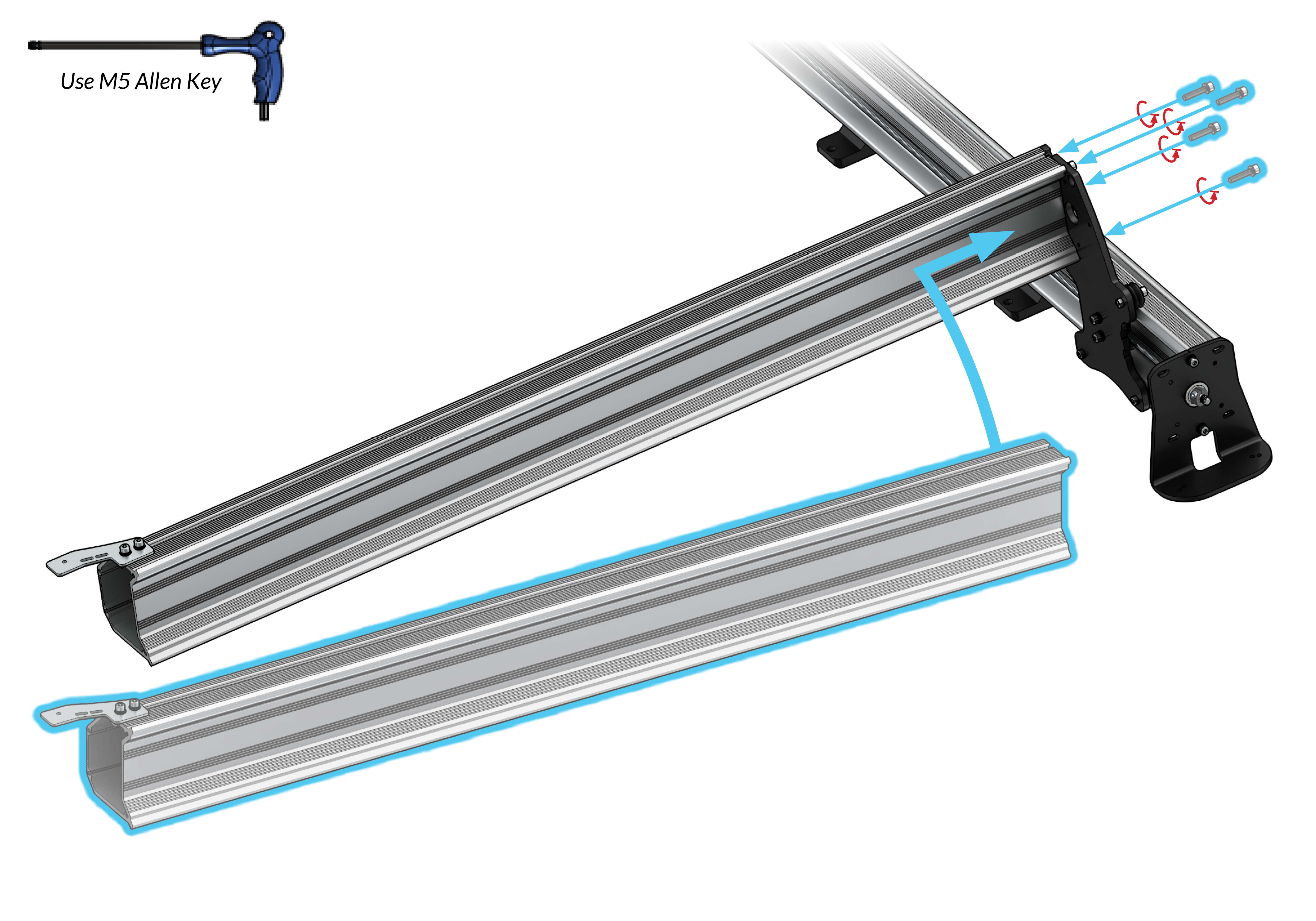
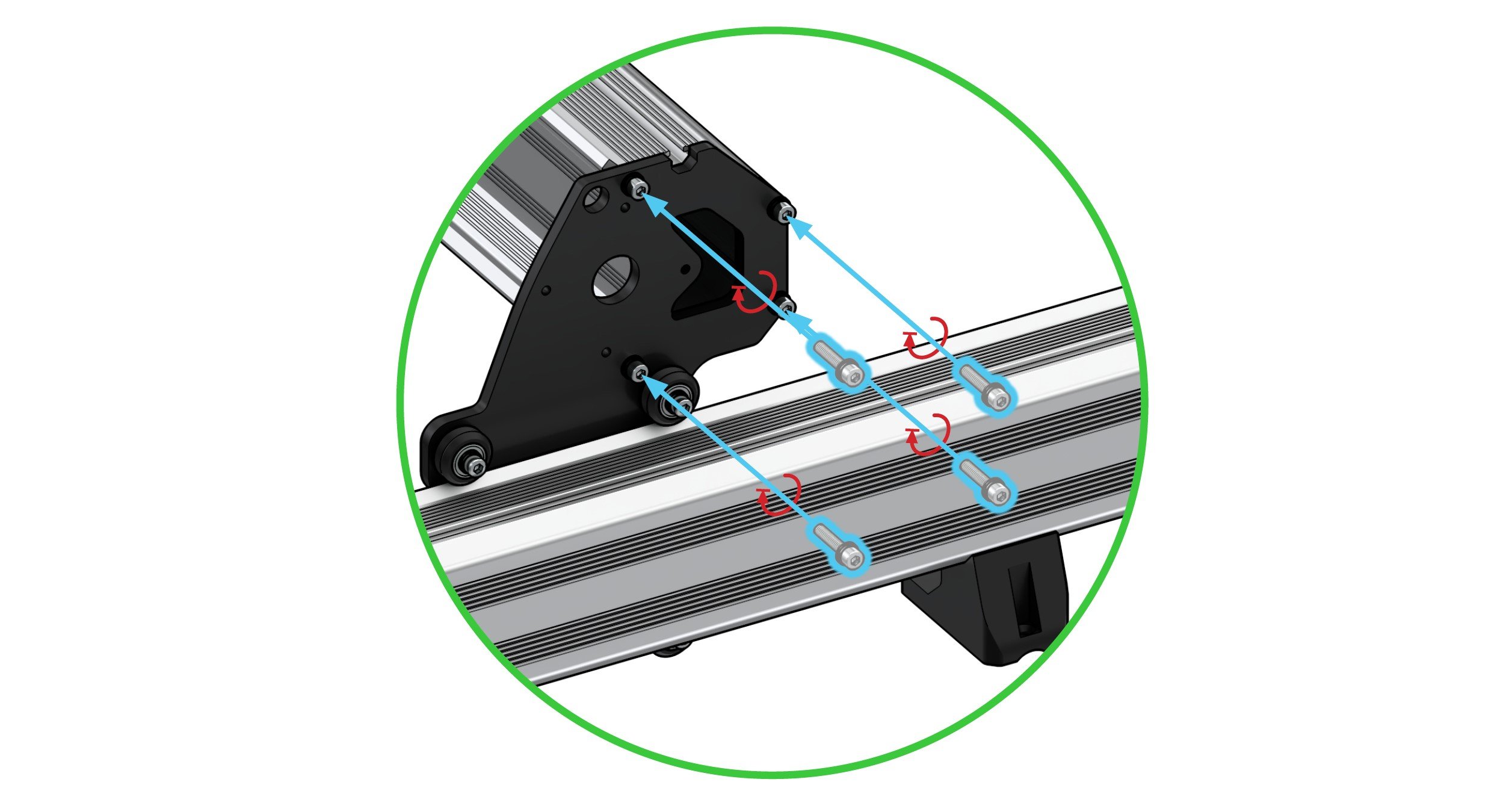
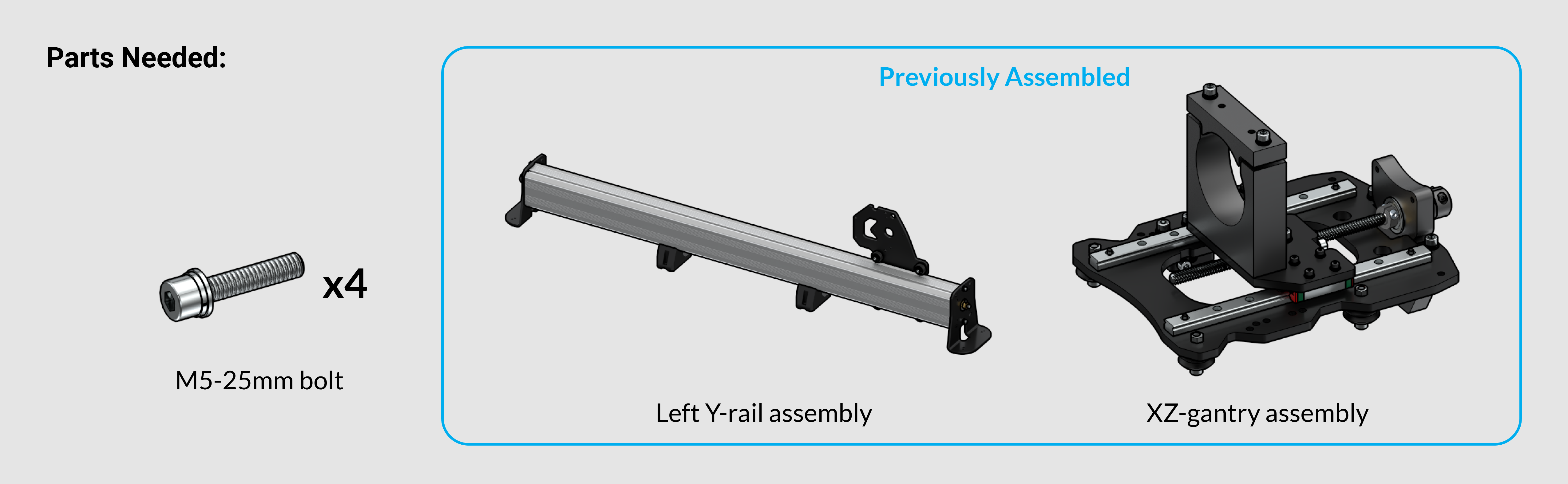
Lift the right side of the X-axis rail up to meet with the matching holes on the right Y-axis gantry plate to assemble them together. Bolt these together using four M5-25mm bolts. Positioning is easy since the shape of the rail matches the shape of the plate top.
Connecting the Remaining Sub-assemblies
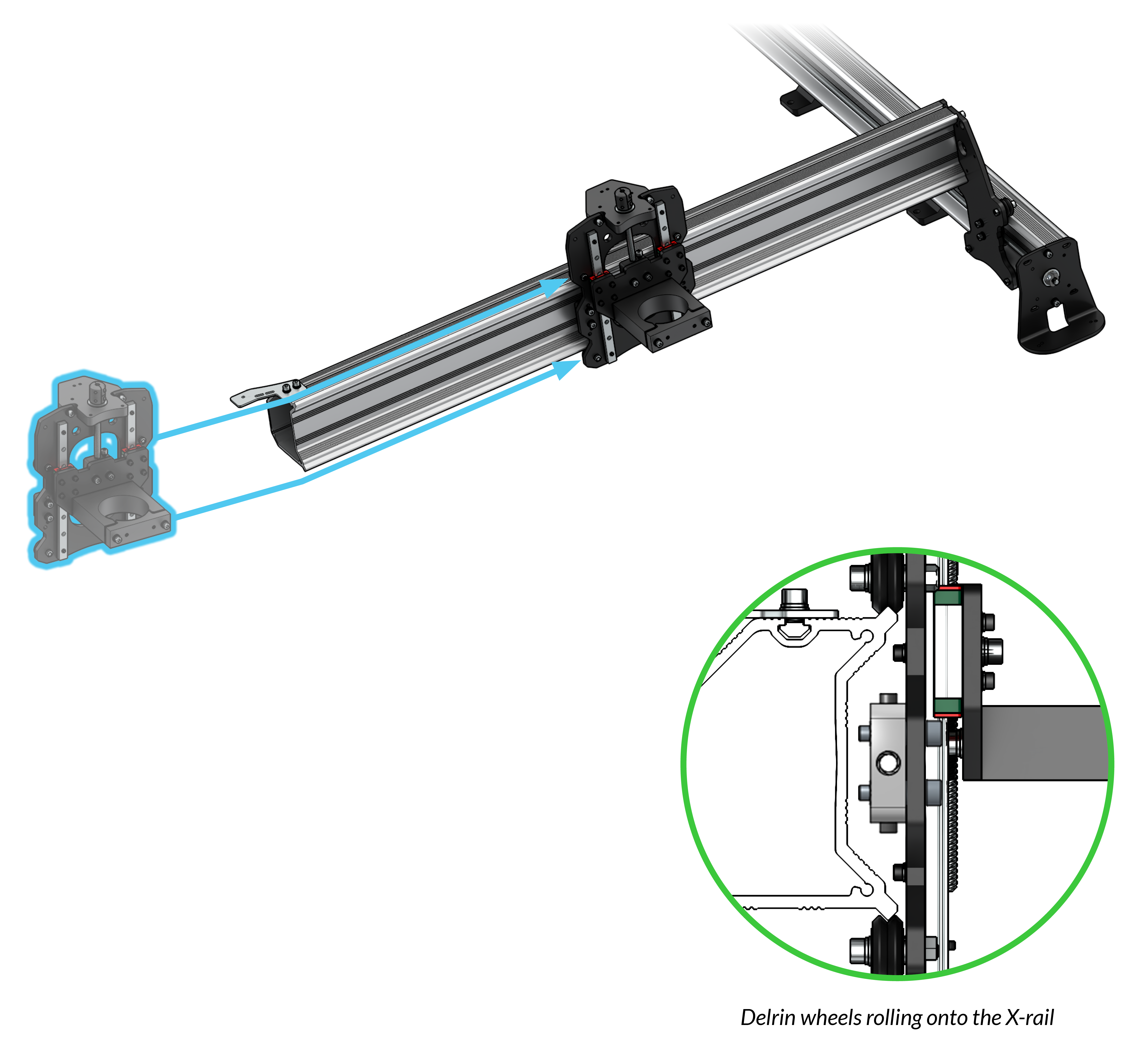
Slide the XZ-gantry onto the X-axis rail. The v-wheels should sit on the pointed edges on each side of the X-axis rail (pictured).
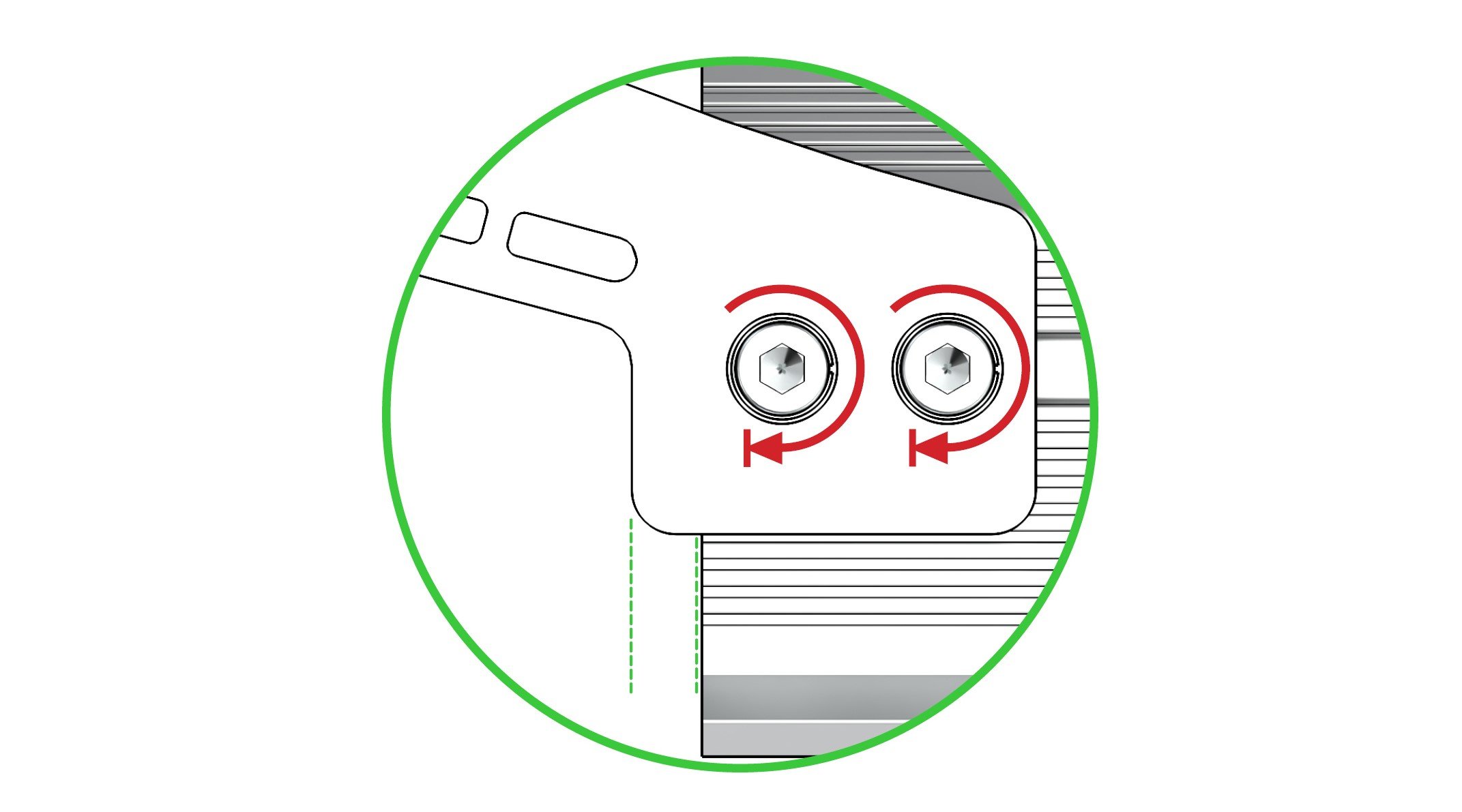
Lift the left side of the X-axis rail up to meet the left Y-gantry assembly. The drag chain mount is there to assist you with positioning by acting as a rest against the top of the plate while you bolt the plate to the rail. Fully fasten using four M5-25mm bolts.
X-axis Lead Screw
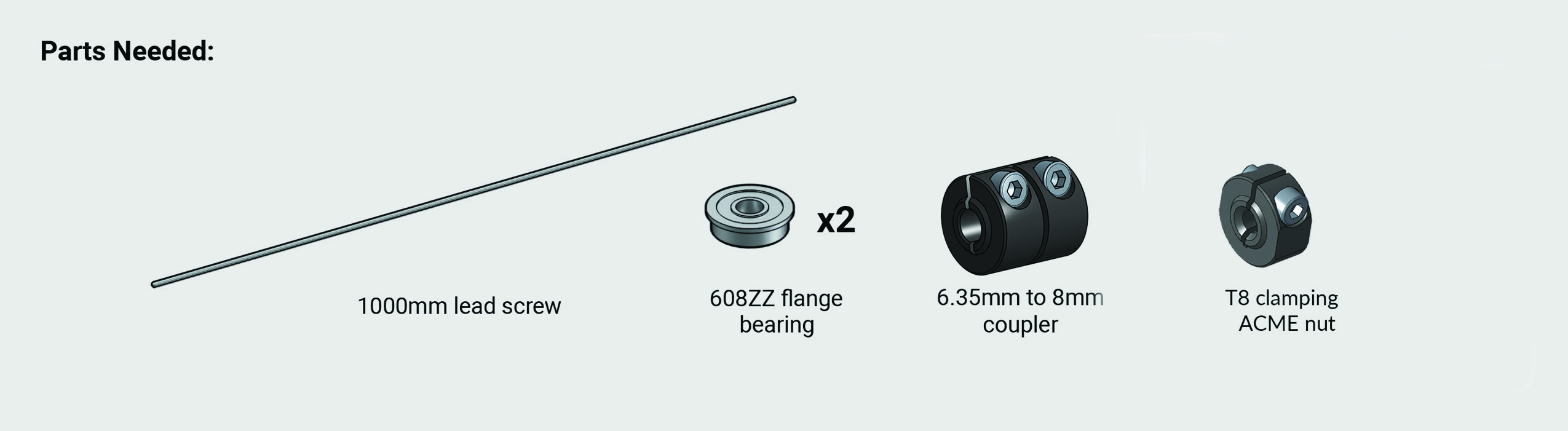
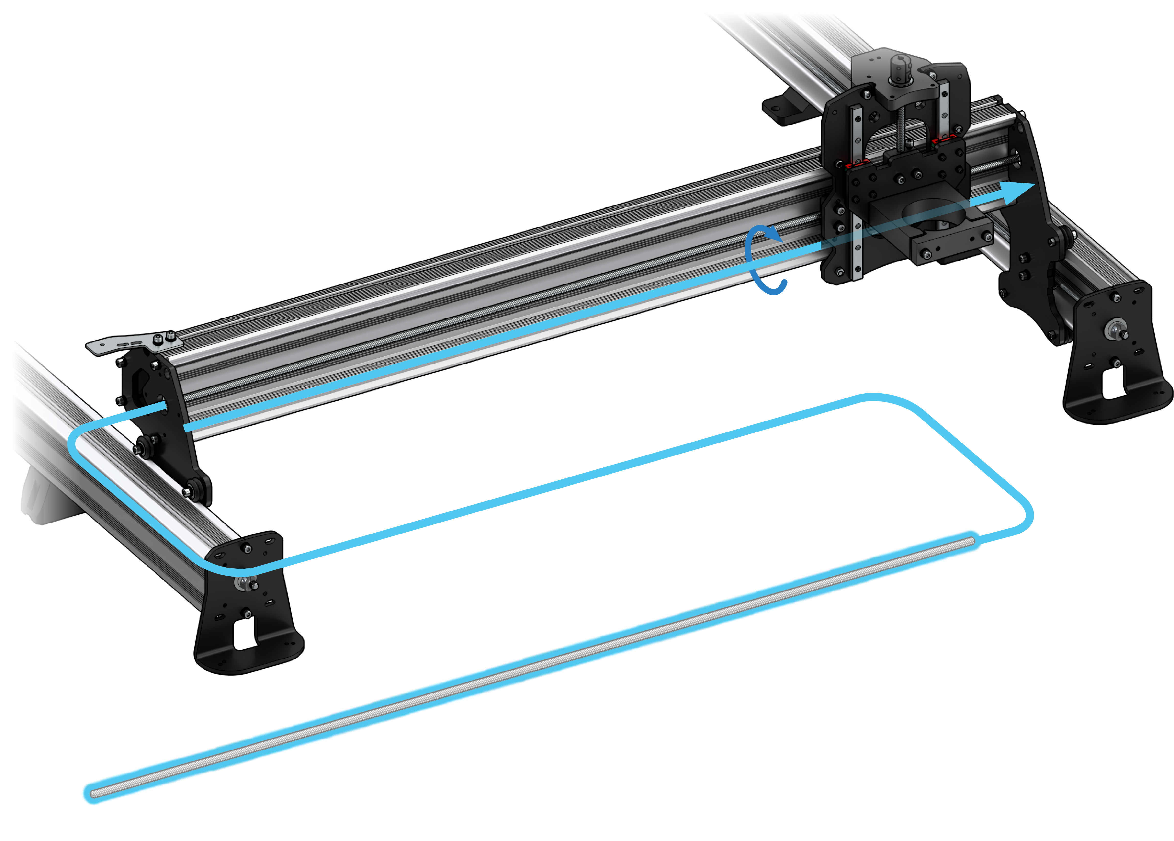
Thread the final lead screw through the anti-backlash block behind the XZ-gantry. The ends of the lead screw should be able to rest in the big holes on both steel Y-gantries. ![]()

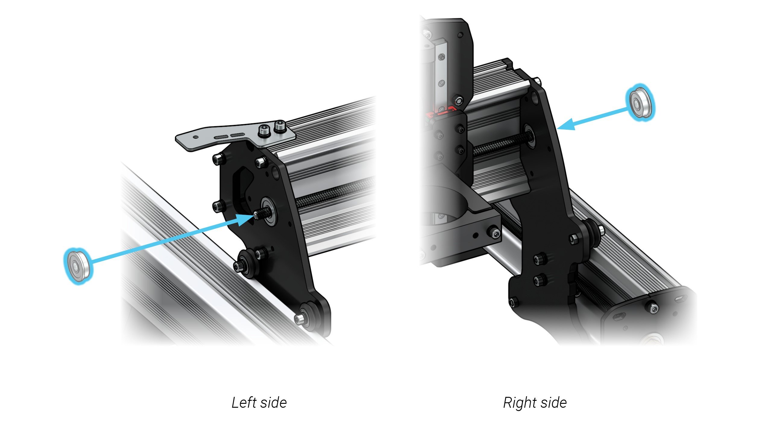
Insert one flange bearing onto each Y-gantry from the outside, making sure the lead screw goes through the bearing.
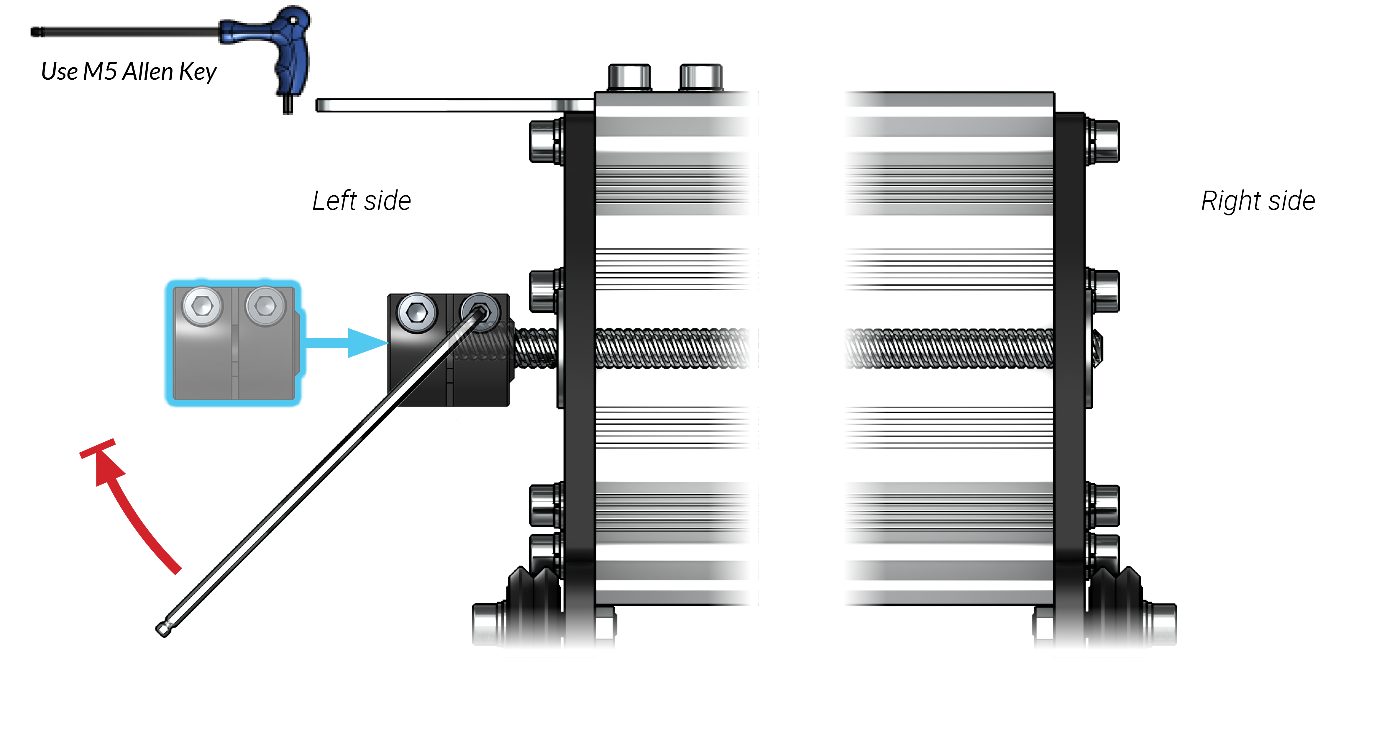
At the left side of the X-axis rail, slide the coupler on until it bottoms out on the lead screw. Firmly secure the coupler at the set screw using an M3 Allen key.
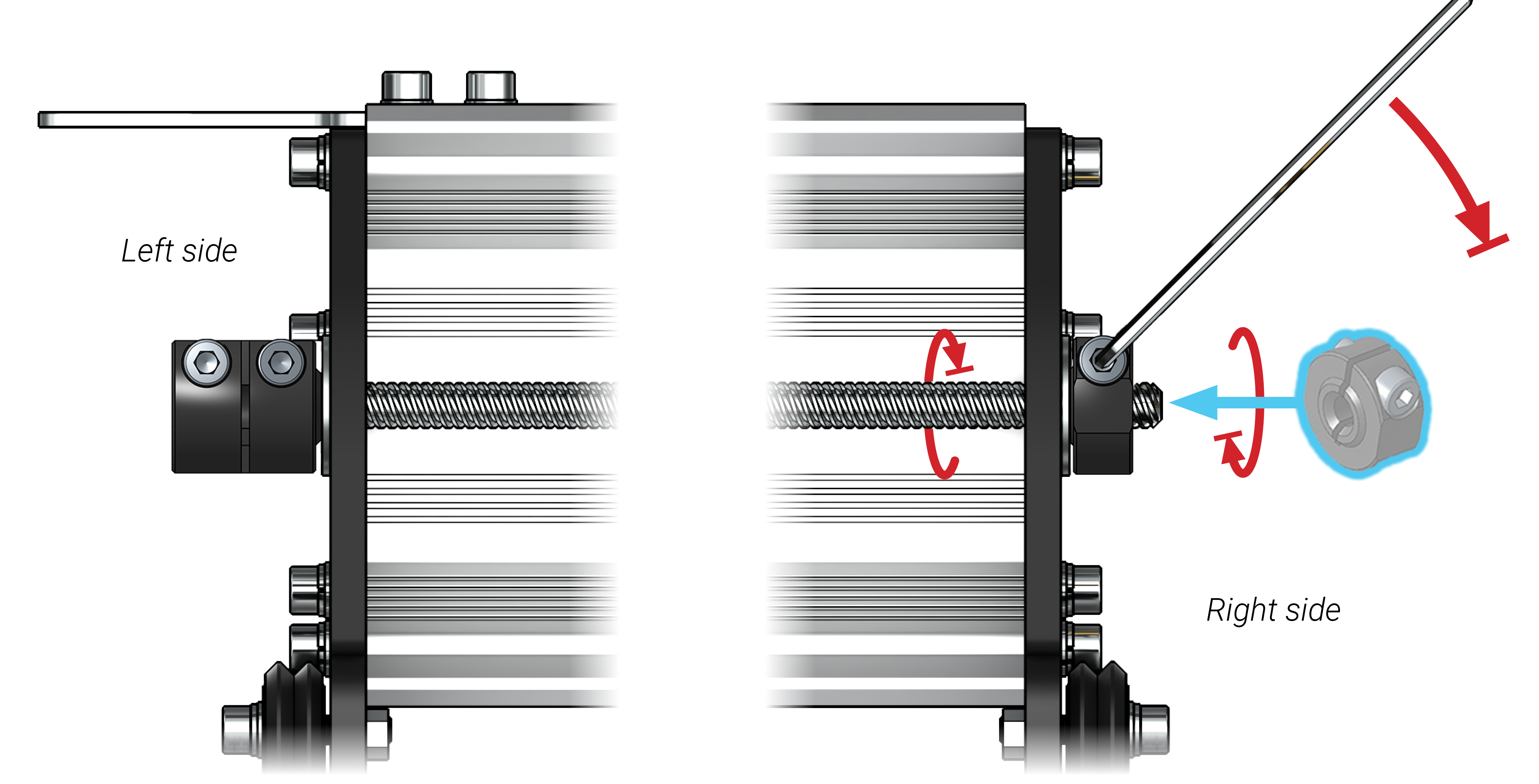
Just like for the Y-axis, use both hands on the right side to thread a locking ACME nut into the lead screw so that it pulls it flush to the flange bearing and brings the coupler flush against the other bearing. While holding this tension in place, firmly tighten the set screw on the ACME nut. This makes another ‘bolted sandwich’ where everything should be touching bearings (as pictured) and the lead screw should only be allowed to rotate, and not move side-to-side.