
Checking & Plugging In
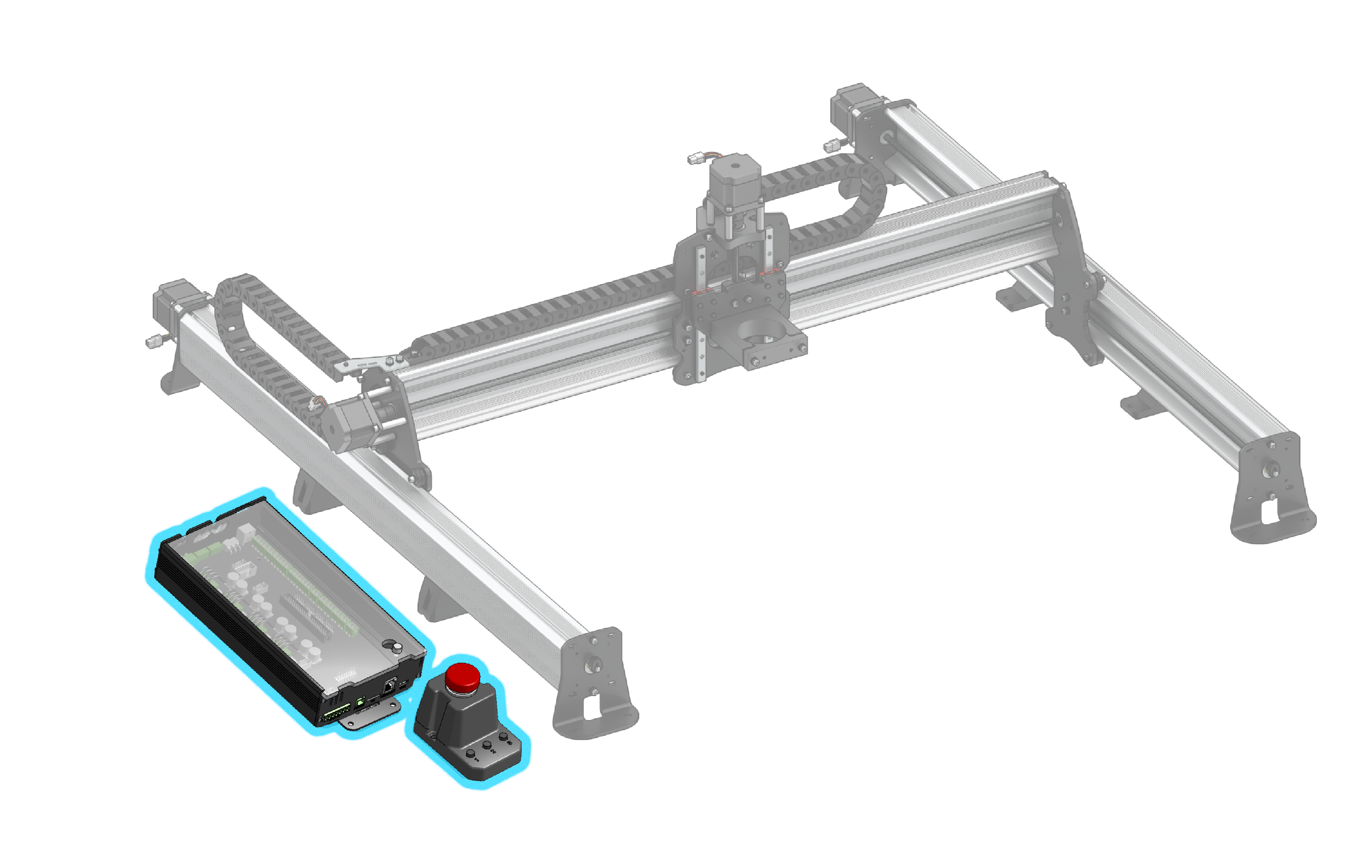
The LongMill electronics come pre-assembled and are pretty much ready to go out of the box. Here are two things you can double-check before plugging in and powering-on.
First, check all wires going into green connectors by tugging on them. This includes the wires to the green motor connectors, green connector from the power supply, and the green connector coming from the E-stop button. Secure them using the screw terminals and a flat head screwdriver if they’re loose or the wires come out entirely.
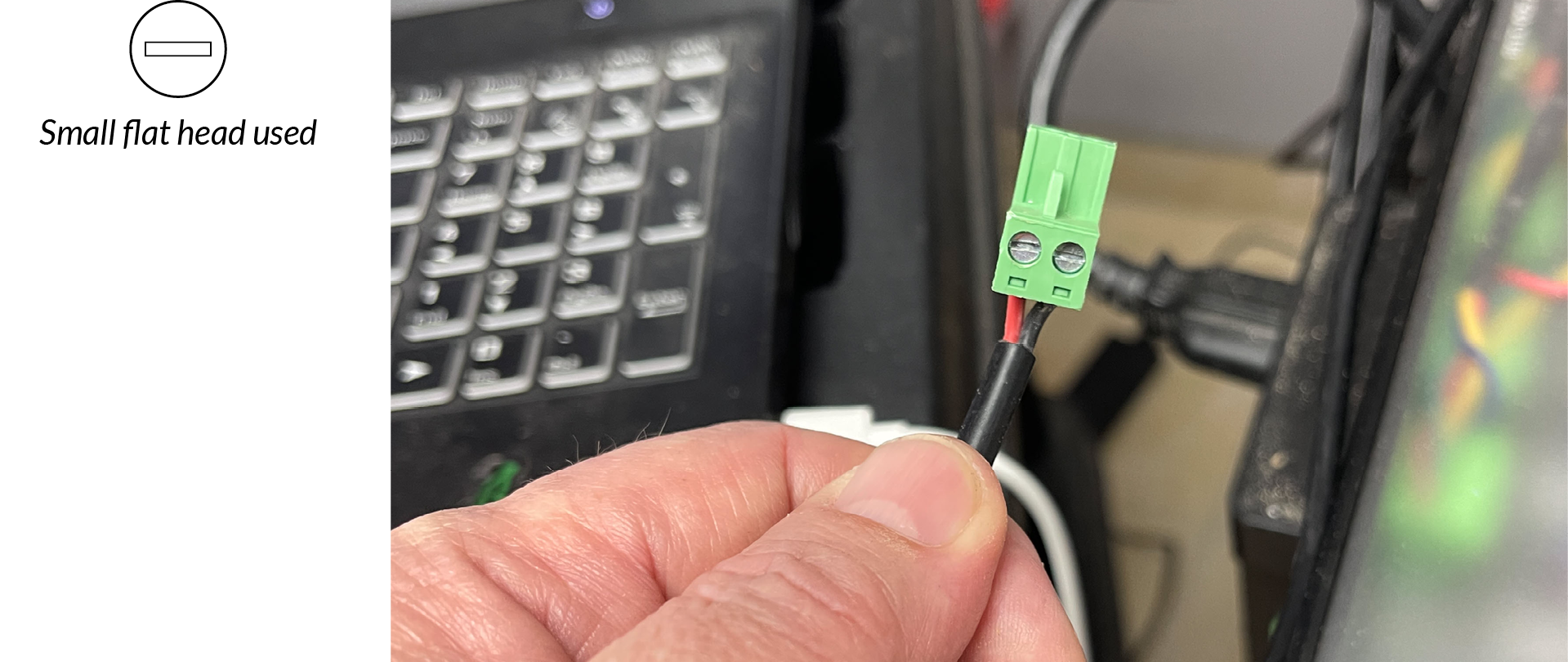
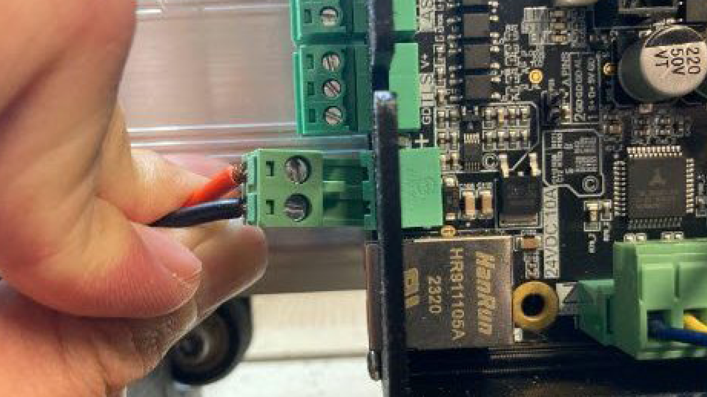
Second, confirm the wire order for the power supply and motors. It’s important that the DC power brick has a white or red wire on the left side and a black one on the right when the screw terminal is facing you (as pictured).
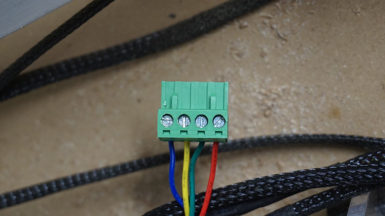
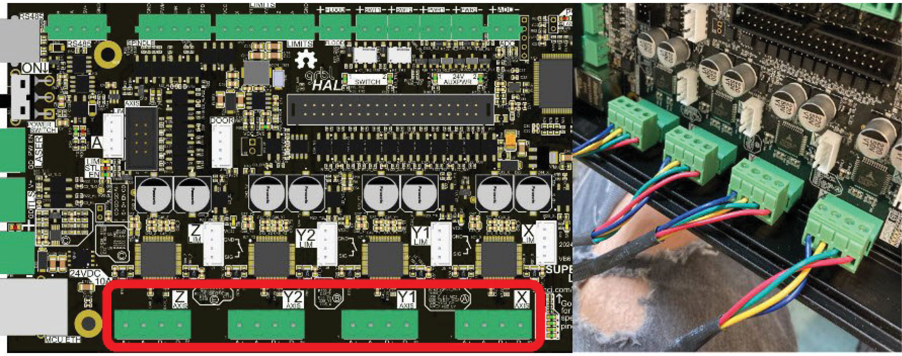
For the motor connector the wires, looking down from the side with the screw heads, should be, from left to right, BLUE, YELLOW, GREEN, RED (pictured). Check if the color pattern on all four of your motor wires is correct and rearrange them if needed.
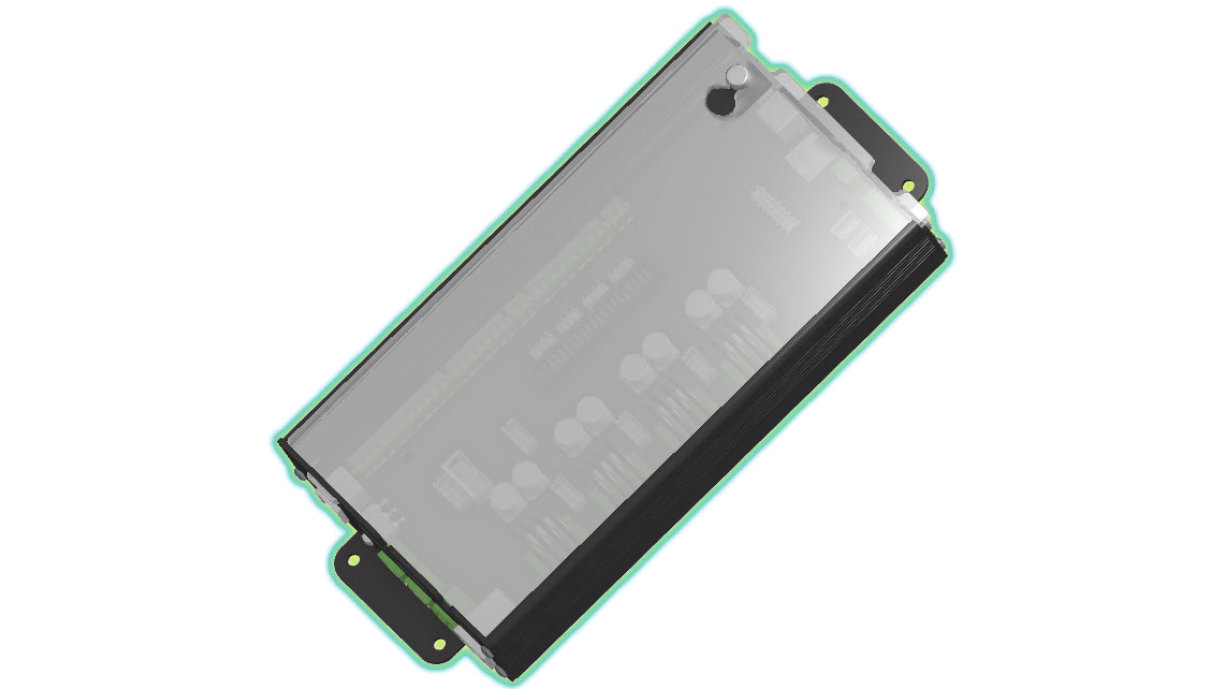
With these checks done, let’s remove the cover on the SLB. Twist the thumb screw in the top right corner counter clockwise to loosen it a bit, then slide the cover to the right.
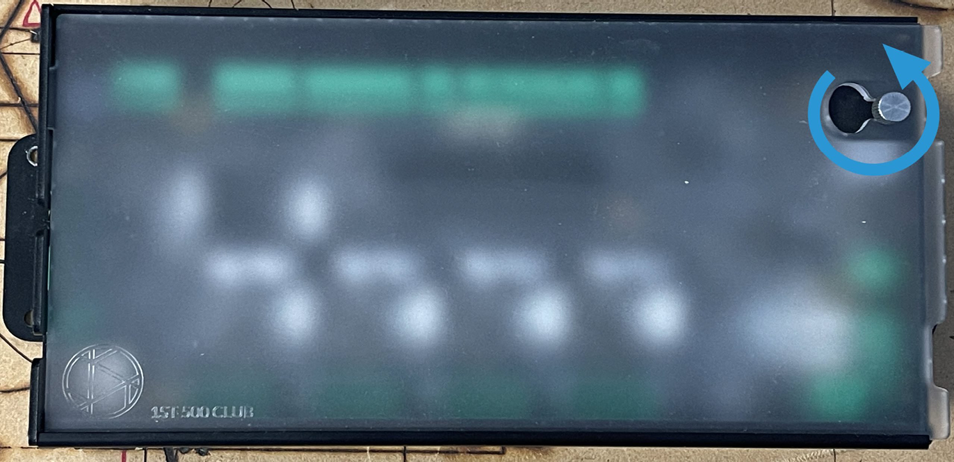
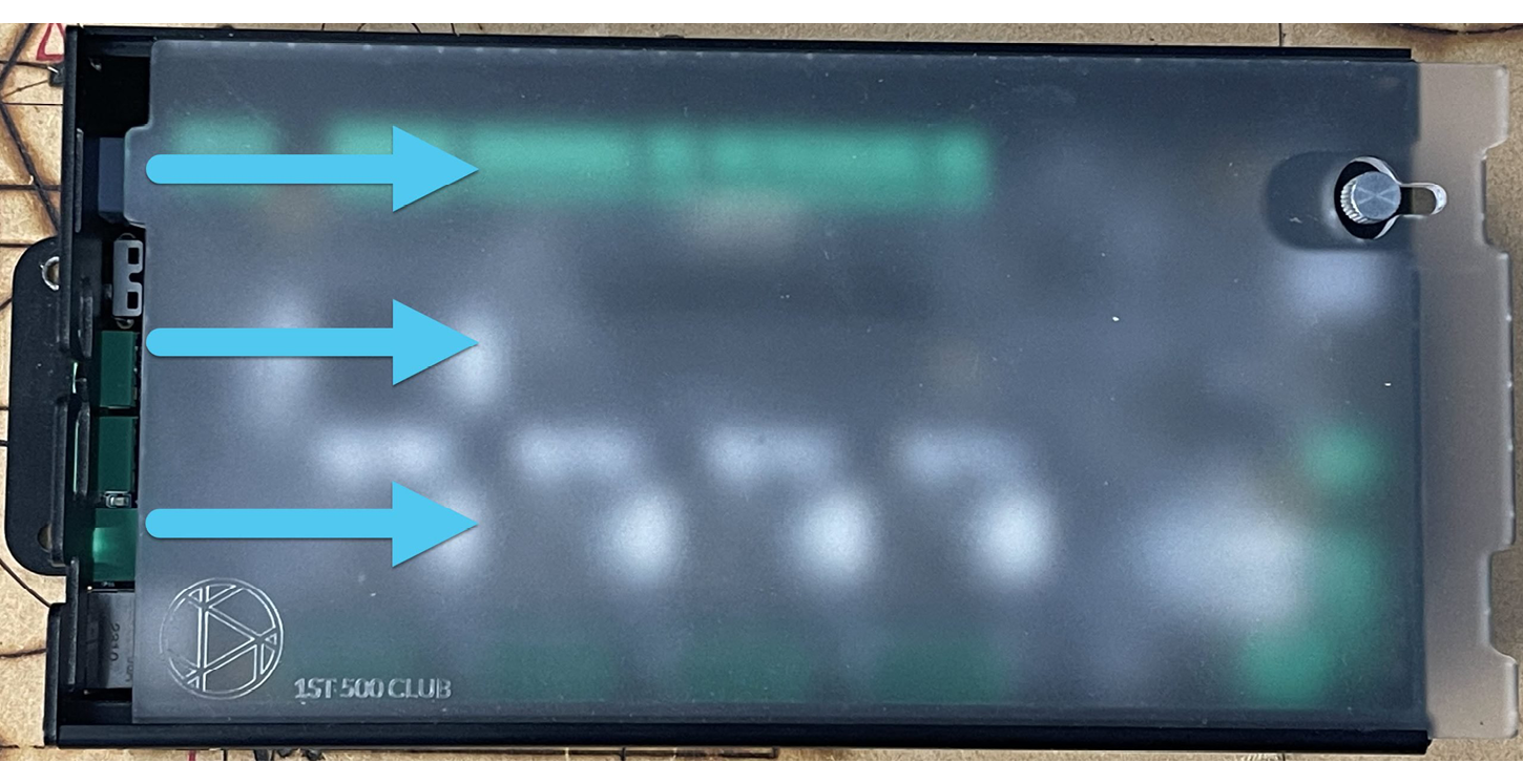
This will allow the thumbscrew to pass through the keyhole. Pull the cover up from the side and you will reveal the motor plugs and all the internal connections.
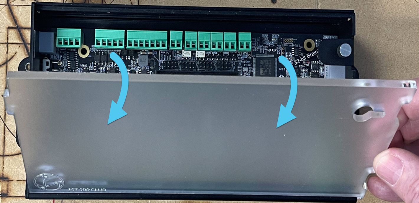
With the cover open, start connecting the motors. Track each cable from each motor to its corresponding green connector and connect it to the board. The fit of these connectors is tight but you need to be sure to push them ALL THE WAY IN so that there is good contact between the plug and the connector. Each plug on the board is labelled on the top.
Note: there isn’t a difference between the Y1 and Y2 plugs, the Y-axis motors can be connected to either of them
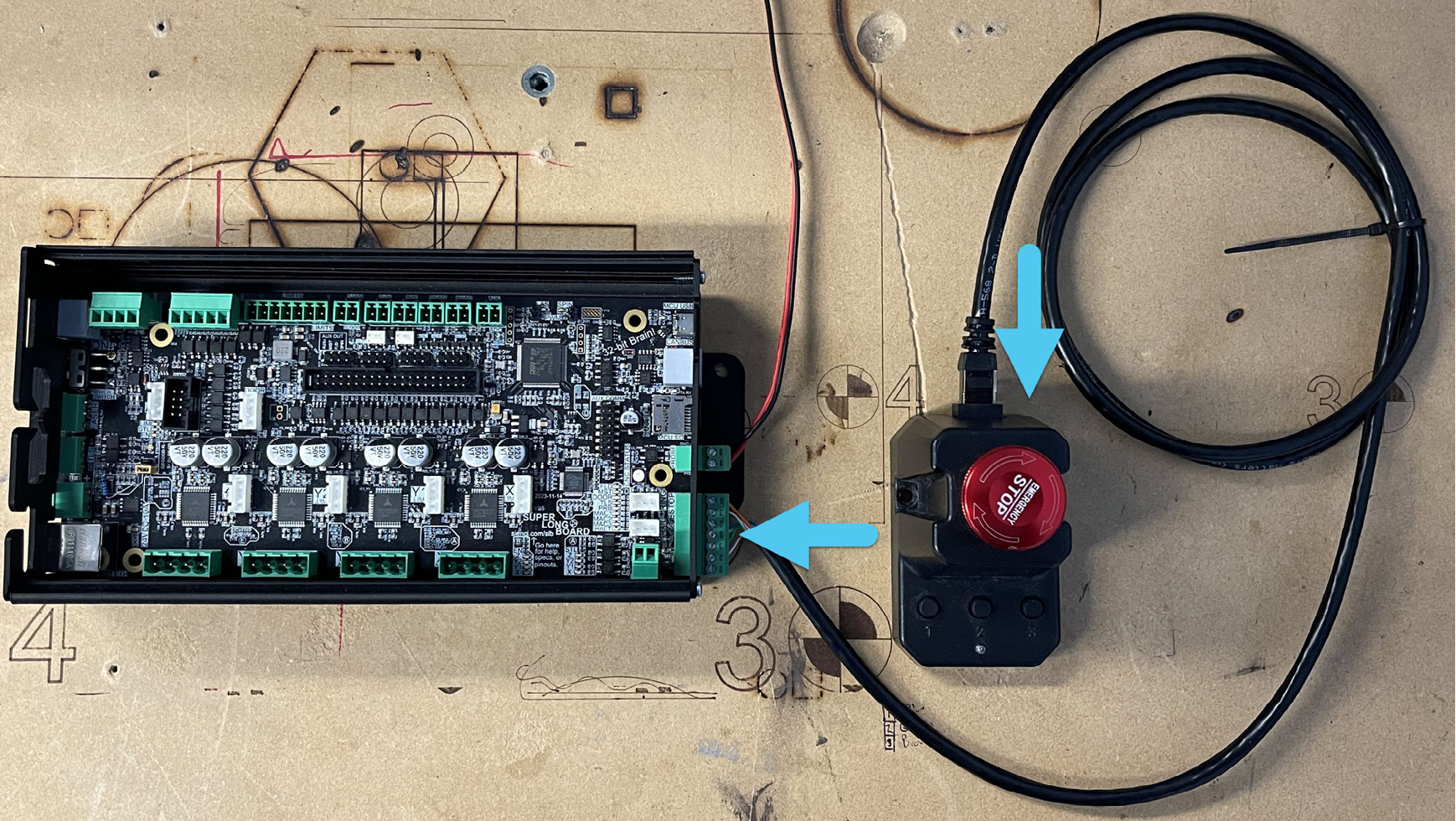
Next, plug the connector coming from the power brick into the rear of the LongMill’s control box (pictured); wait until after it’s plugged in before plugging the AC cable on the other end into the wall.
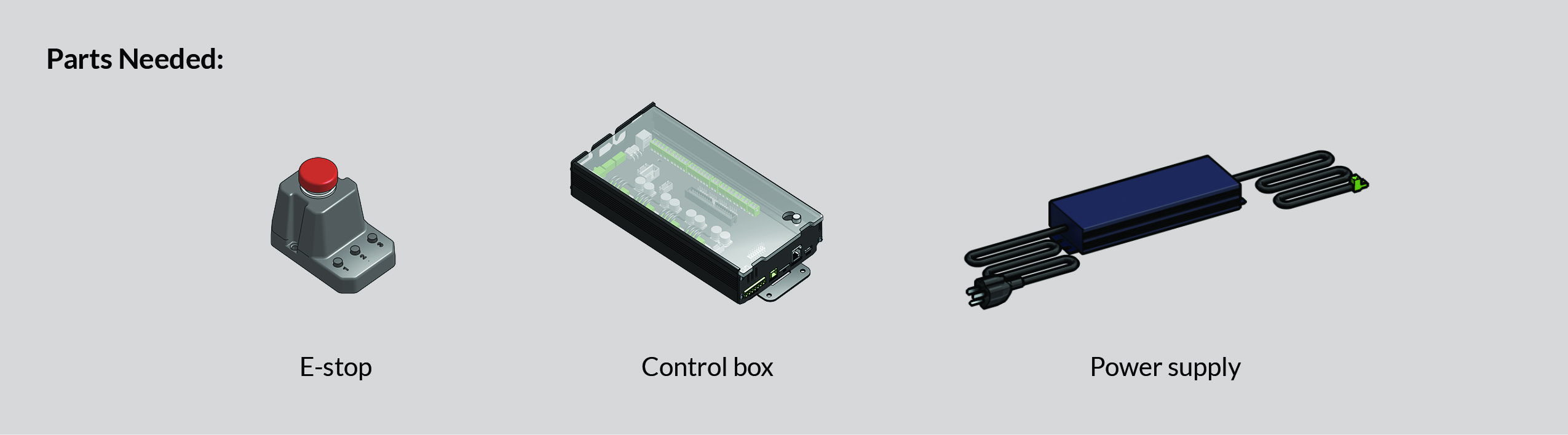
Now, connect the emergency stop button to the control box via the connector on the front. You should be able to find your E-stop button (pictured on the right) in the SuperLongBoard box.
Next we will be connecting to your computer, booting up gSender and then running some quick tests.
Connecting the LongMill to your Computer
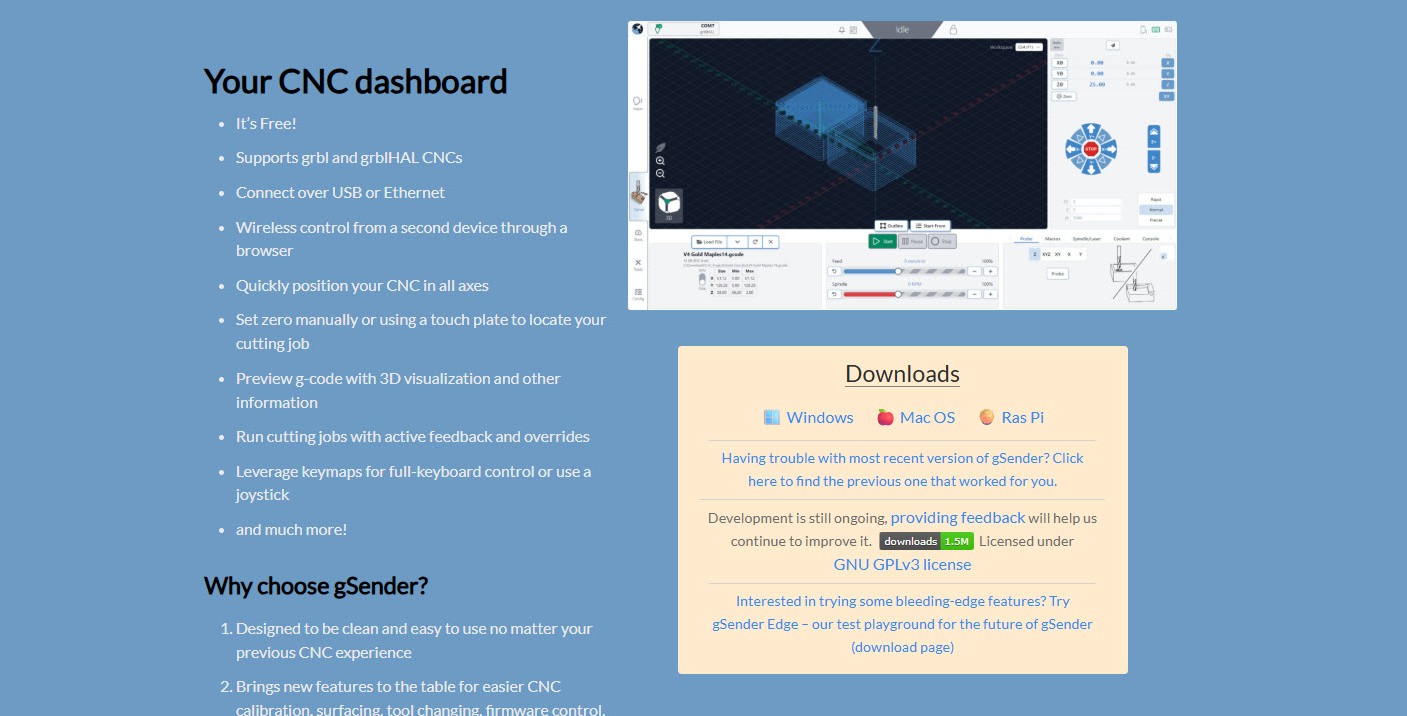
To manipulate your LongMill and send it files, you’ll need a g-code sender which acts as the ‘control software’ or ‘machine interface’ to your CNC:
- We recommend using gSender for this since it’s our own software and it’s easy to use
- We’ll use gSender for the remaining assembly steps, download it here: https://sienci.com/gSender/ and choose for Windows / PC , Mac, Linux, or others.
- If you get stuck at any point or want to learn more about gSender you can always find more help here
- There are still other options you can see in our ‘Software’ resources if you prefer them, but make sure they are able to communicate with “grblHAL” machines, if they only support “grbl” then they won’t work for your LongMill
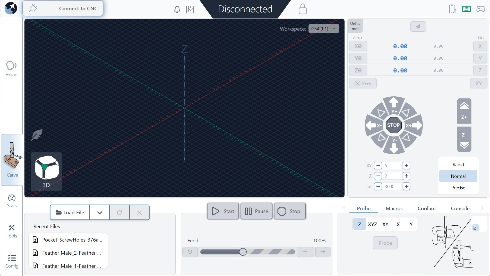
Once you have gSender installed, go ahead and run it on your computer. One way is to double-click the shortcut on your desktop.

You should be greeted with a screen that looks like this. It can take several extra seconds to load if you have Microsoft real time virus protection on your computer. This scan delay should only happen the first time you turn on your computer.
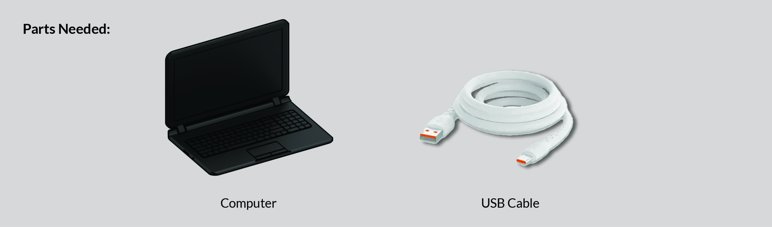
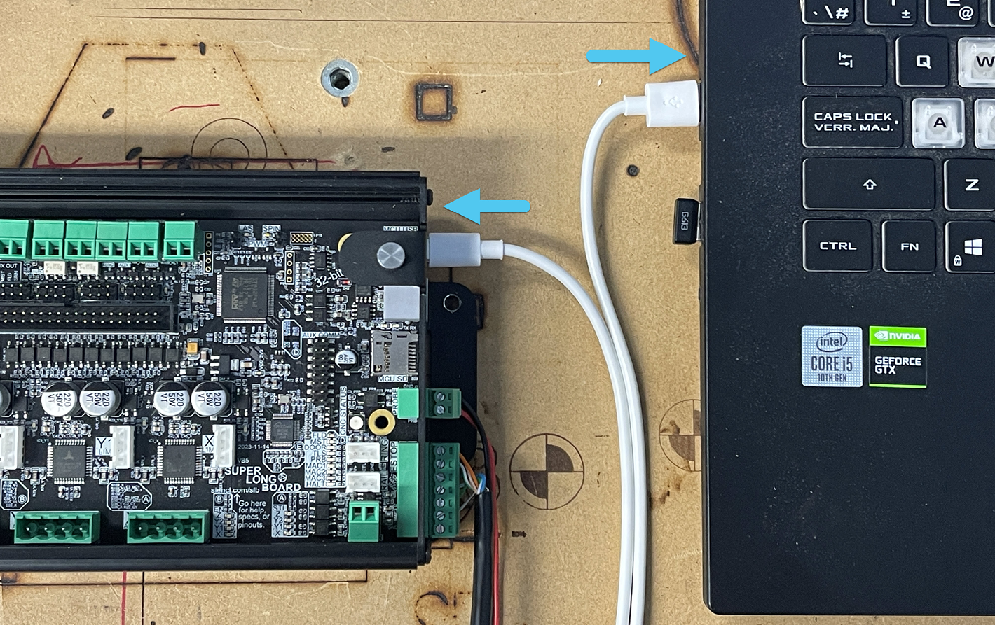
At this stage it’s time to connect your computer to the LongMill control box via the provided USB cable and flip the power switch to turn on power to the machine. The USB port on the control box is on the right side.
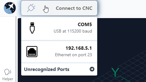
Once that is done, hover over the Connect to CNC button at the top left corner of the screen and click the first option. Sometimes there’s more than one port available, so you can either unplug the other items you have plugged in, or you can try connecting to each one to see which one is your LongMill (note that it’s recommended to connect this way on your first setup even if you’re planning to use Ethernet in the long-run).
After a moment you should see the plug icon turn green with a checkmark, the status bar at the top, middle change from Disconnected to Idle, and all the controls in the app become coloured indicating that they’re ready to be used.
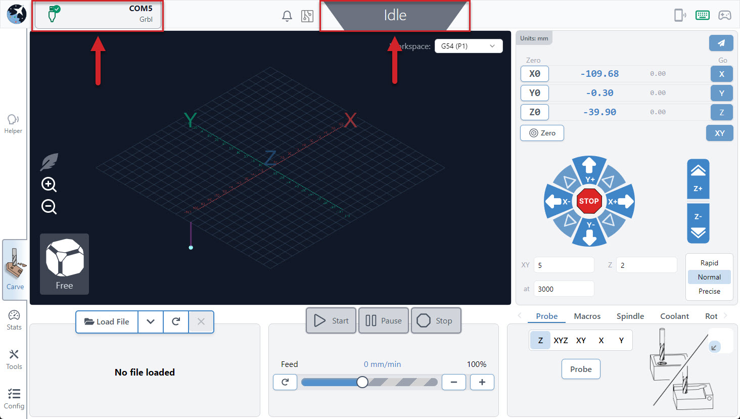
With “Connect to Machine” changed to “Connected”, the plug icon turned green with a check mark, the status on the top right corner of the visualizer changed from “Disconnected” to “Idle”, and the other controls that were greyed now being activated, it’s time to take your CNC for a drive!
Quick Tests
Now that we have the basics plugged in and are connected in gSender, we’re going to test out a couple things. This will help catch any issues before the SLB controller is more permanently mounted or you start on your wire management ;). Let’s put this LongMill through some paces eh?!!
Power On Test
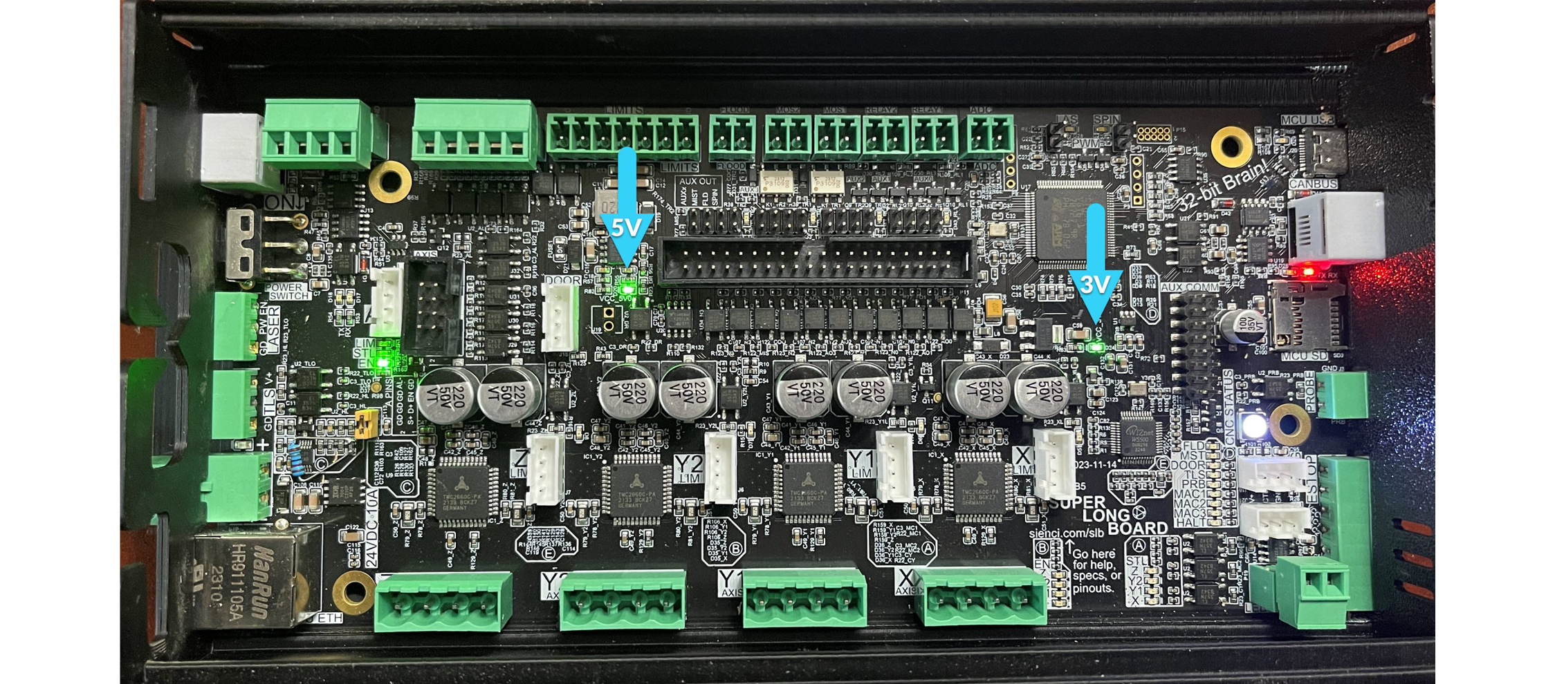
When the board is receiving power, you will see two specific green lights come on. One shows you that your 5V power is active, and the other shows that your 3.3V current is working.
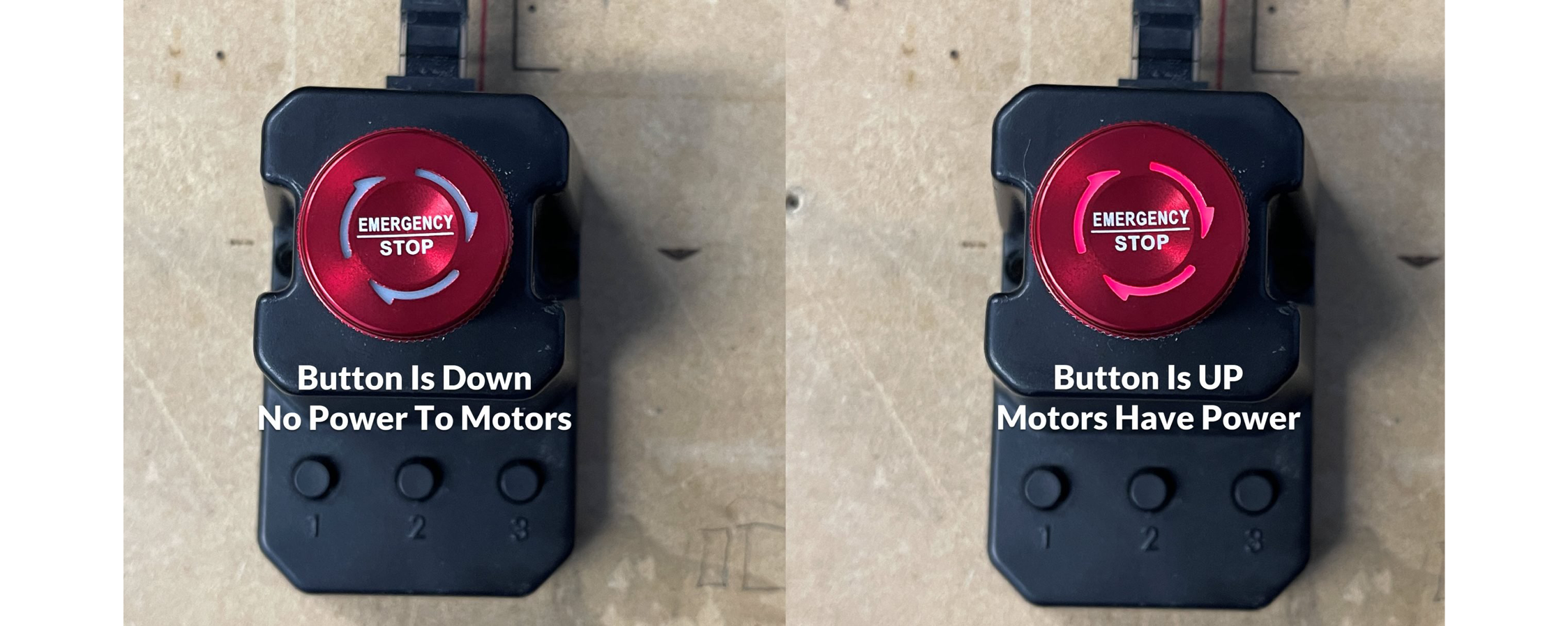
Now hit the E-stop button (it may already be pressed down). When you press it down, the E-stop button will go dark and power to the motors will be cut. You may see the light on the top of the button, or on the base of the E-stop.
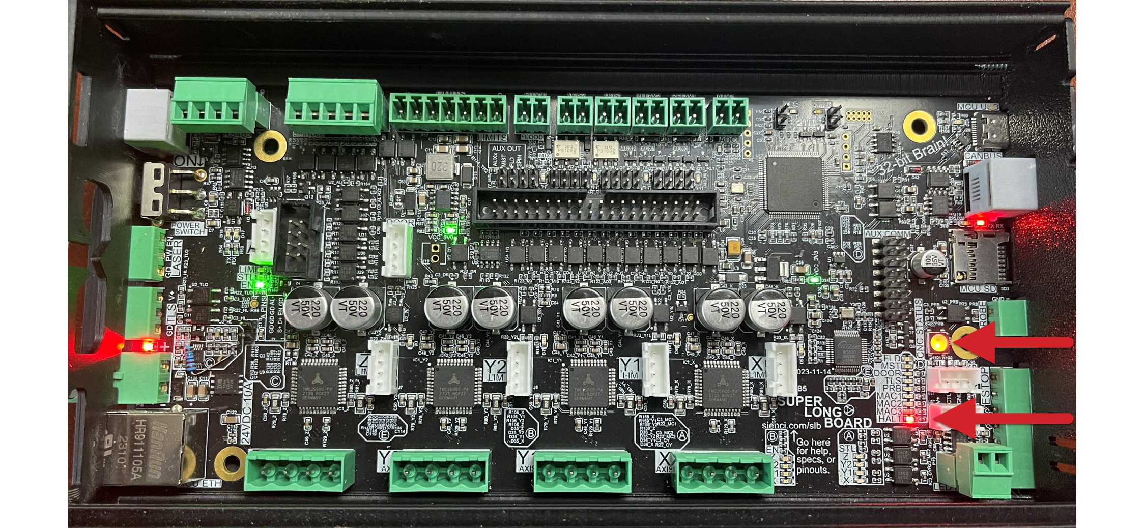
The SLB will respond by turning several lights RED. Most notably your CNC Status light and a very small led called HALT will both turn red.
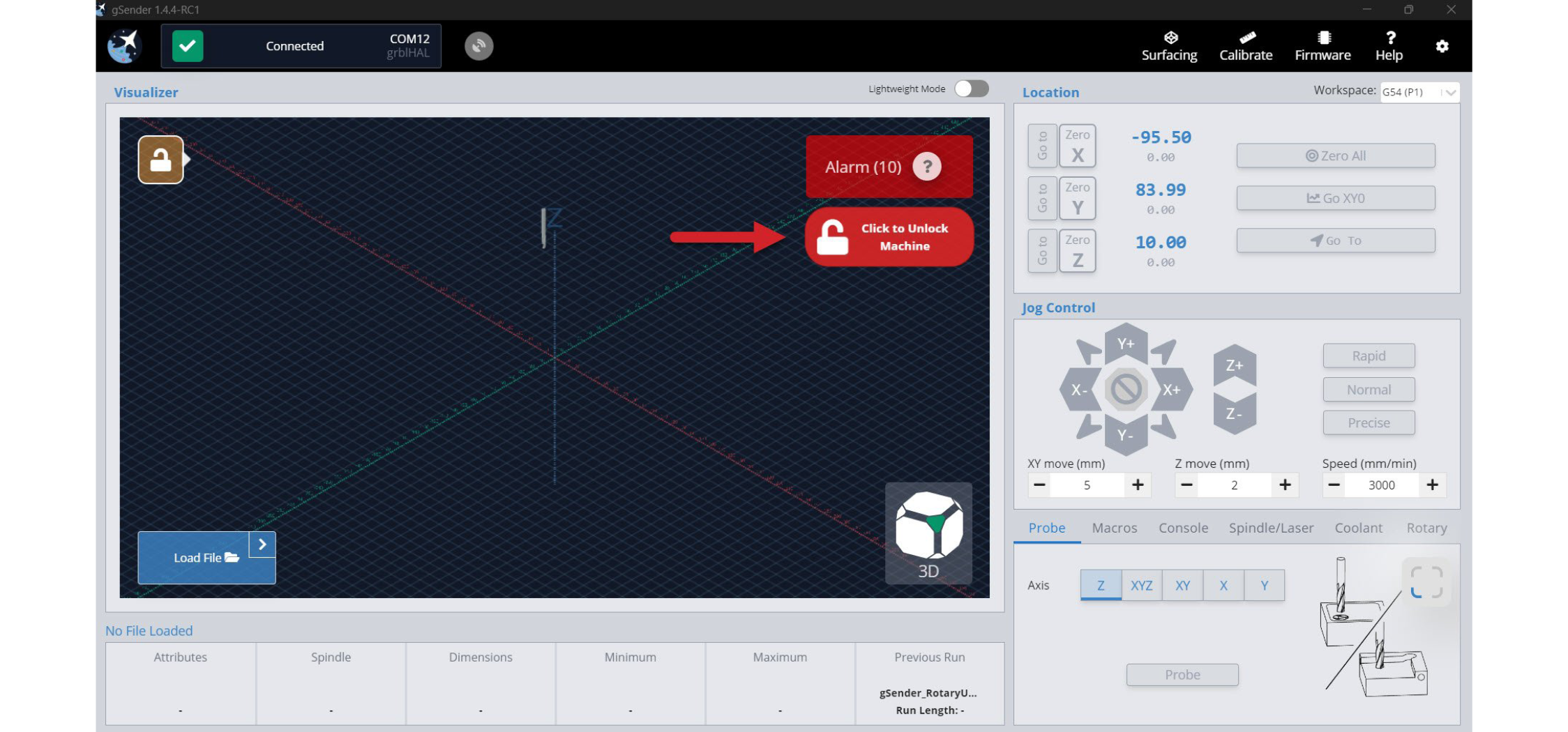
Now we can deactivate the E-stop button by turning it clockwise until it’s raised again. You will see the E-stop button light come back on when raised correctly. We will need to unlock the SLB in gSender by pressing the Click to Unlock Machine button.
Congrats! You’ve completed the Power On Quick Test.
If your lights didn’t come on or you experienced unusual behavior:
- Check that the power supply is plugged into the wall, the brick, and the board
- Ensure there is a light on the power supply (our new blue power supplies don’t have one)
- Ensure the SLB power switch has been flipped to be ‘ON’
- Ensure there are lights on the board
Move Test
Using the jog controls on the main page of gSender, try moving your machine around in the X, Y and Z-axes. Make sure they’re going in the correct directions.
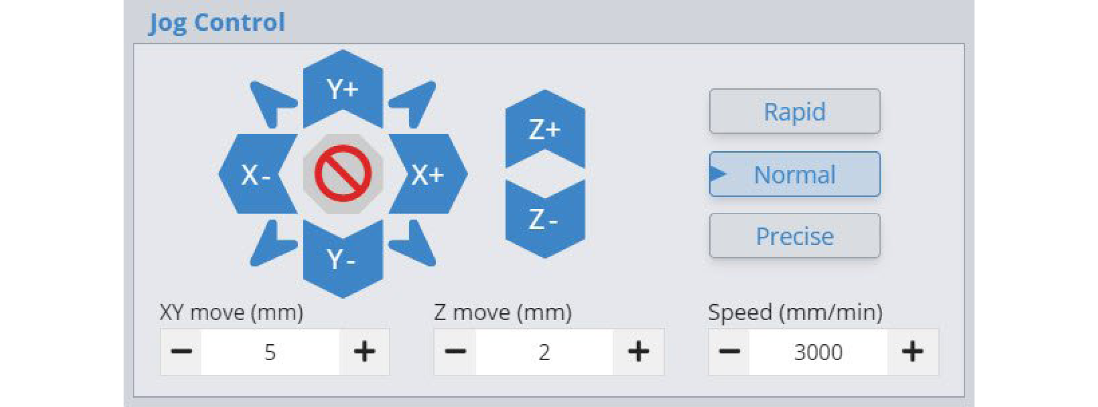
If you find that your axes are not moving in the correct direction, you can go into your firmware settings and change the axis that’s wrong. Also, if you notice that your CNC reacts intermittently at higher speeds then you might have to either spend some more time tuning your machine’s mechanics, or consider lowering the SLBs maximum speed with settings 110, 110, and 112.
Touch Plate Test
One last test is to check that your touch plate works. Navigate to the Probe tab and hit the ‘Probe’ button.
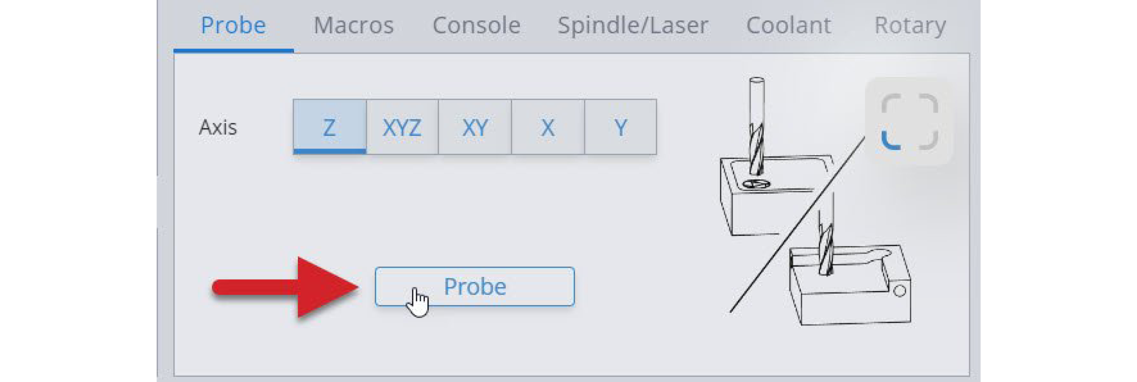
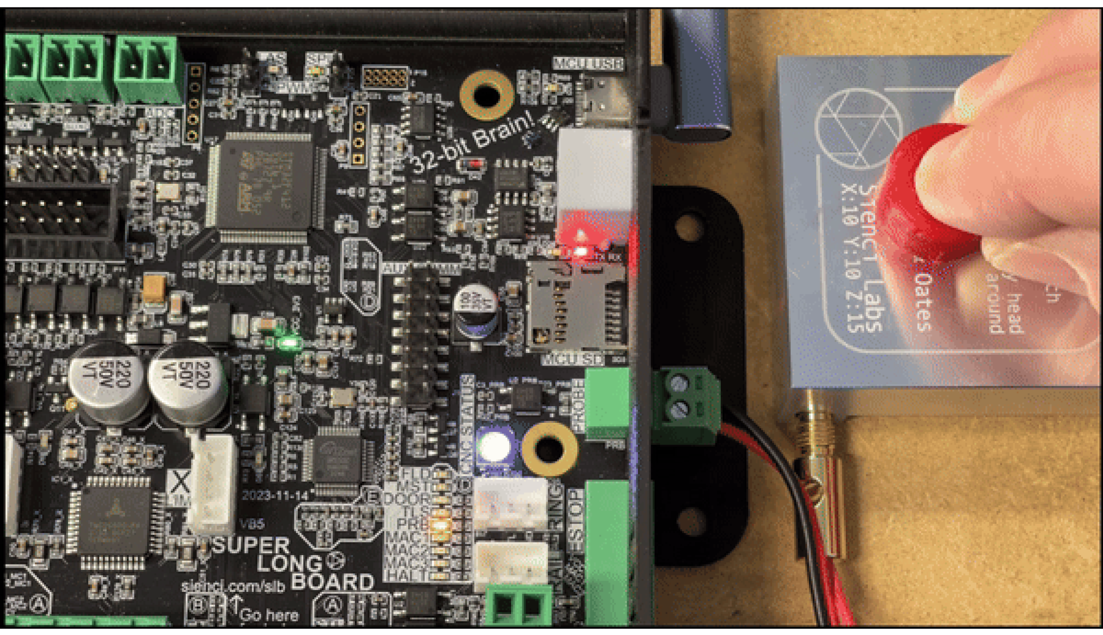
Then, tap the magnet to the touch plate. You will see the yellow PRB light on the SLB.
You’ll know you are successful if the popup button turns blue, and says “Start Probe”.
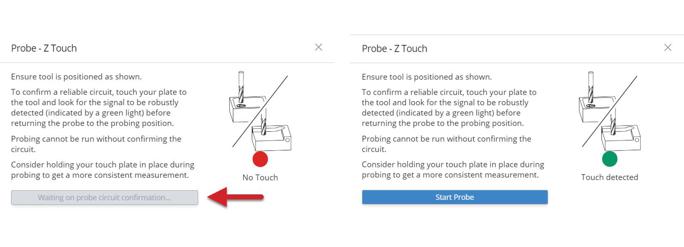
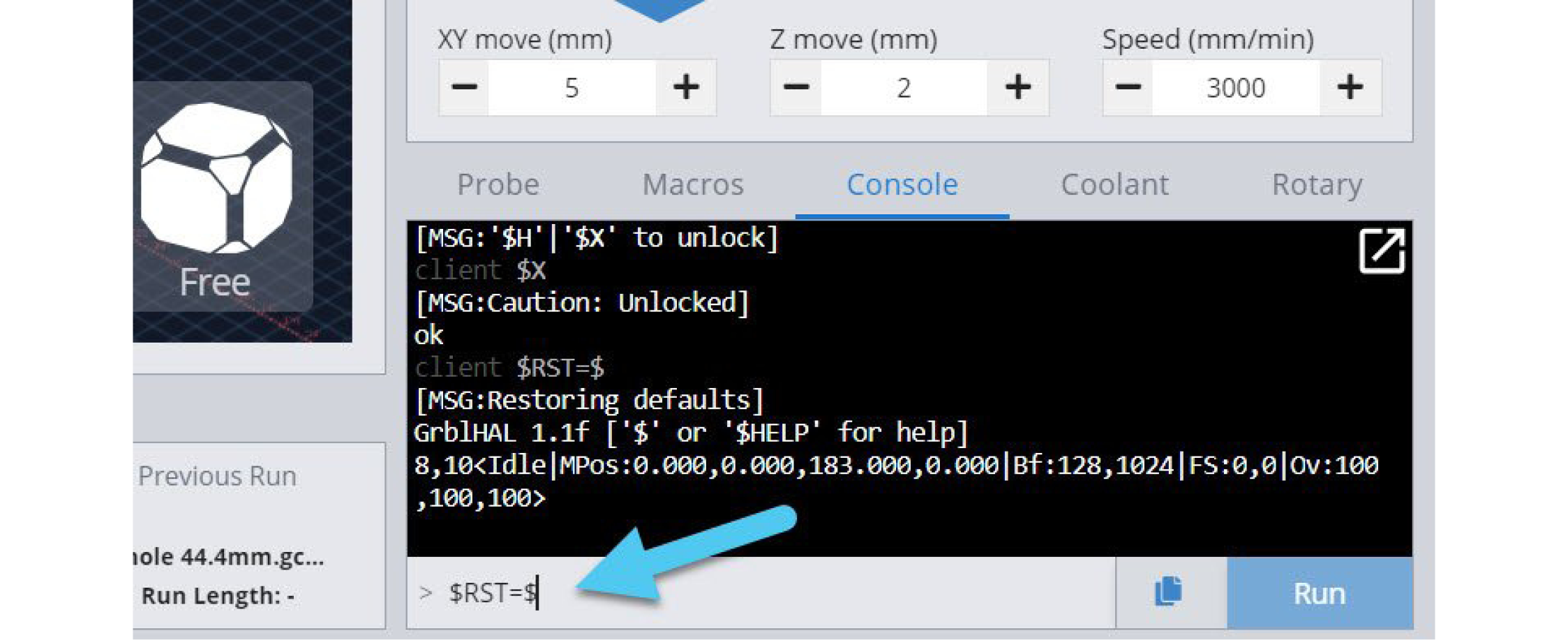
If the light is coming on but the popup button isn’t turning blue, this can sometimes be fixed by resetting your board settings. Do this by typing $rst=$ into the console tab and hitting Enter, then use the power switch on the back of the board to “power-cycle” it off and back on again. Once you reconnect in gSender you can try probing again.
Congrats! Your Quick tests are now complete. This means that all our basic accessories should now be set up and ready to use on your LongMill!
Things will still be a bit loose right now since we haven’t yet tuned up the movement of the machine, but tuning will be the next step and knowing how to move the machine around will be important for when we mount it to a table. While we’re here, take a moment to move each axis to each extreme while checking that the drag chains are reaching to all corners; especially for the y-axis. Don’t be shy moving around, if you hear electronic music that’s normal and if you hear a grinding noise when you hit the limits that’s normal as well.
Tuning Movement
With the machine together and moving, it’s time to tune its movement before we attach it to its work surface. Most of these tuning steps will be the same ones you’ll use when performing maintenance on your machine.
Like other CNCs, and especially for hobby-grade machines, parts need to exist that can cancel out cutting inaccuracies by compensating for wear over time and the initial user assembly. For the LongMill these parts are the v-wheels, eccentric nuts, and the anti-backlash nuts. We chose these parts because they’re commonly available and easy to use once you become familiar with them. Let’s start with the v-wheels and eccentric nuts.
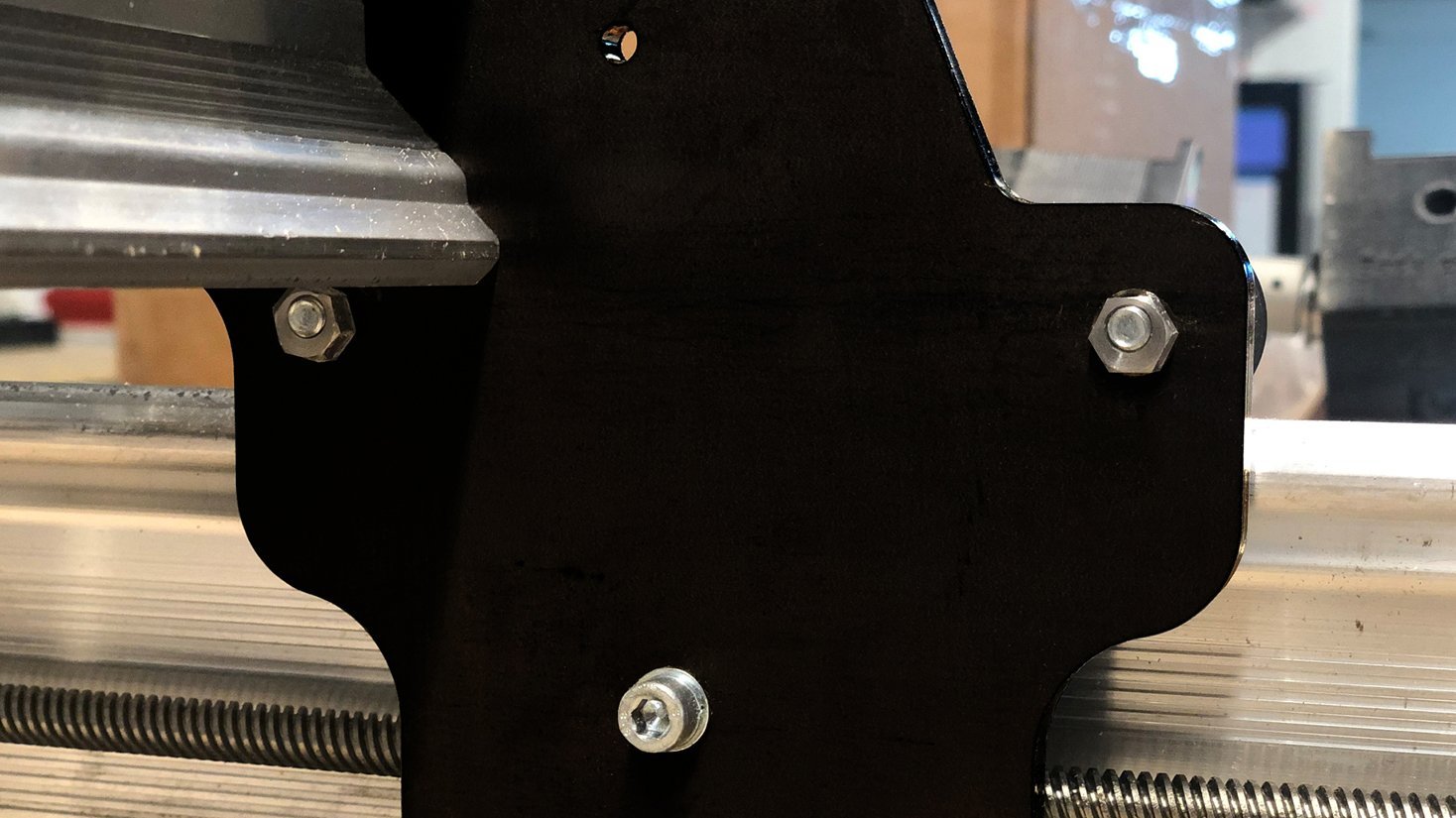
Recall that during assembly each steel gantry was fitted with one set of firmly bolted v-wheels and another set of loosely attached wheels with eccentric nuts, these loosely bolted ones are the ones we’ll be returning to to finish tightening them up. For the Y-axis these are the top v-wheels (pictured) and for the X-axis these are the bottom. We’ll work on these one plate at a time.
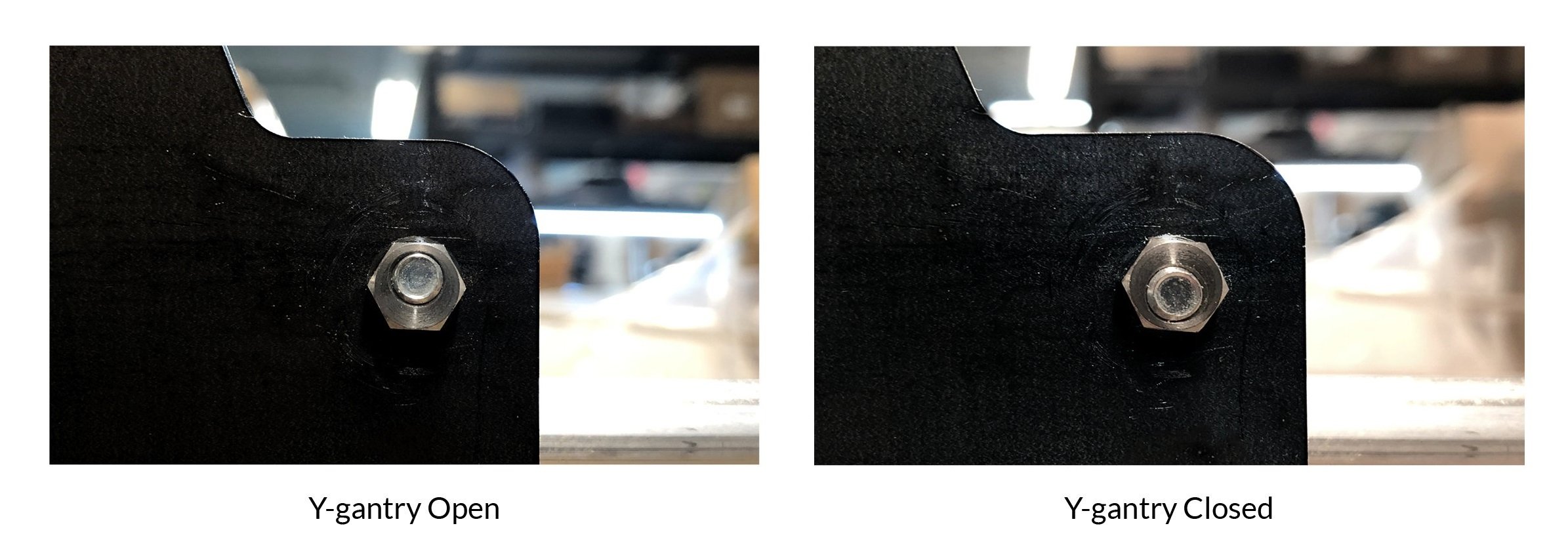
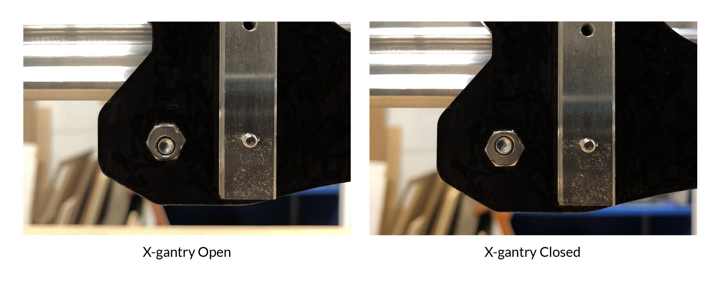
Eccentric nuts are ‘eccentric’ or ‘off center’ nuts and this means that by turning them you can change the gap between the v-wheels attached to them and the fixed v-wheels on the other side of the rail. We call this ‘tensioning’, a system where the wheels can clamp onto the rails enough to not move around loosely but still create smooth motion. You can see below what it looks like when an eccentric nut is all the way open (largest gap between wheels) and all the way closed (smallest gap between wheels) for both the Y and X-axes.
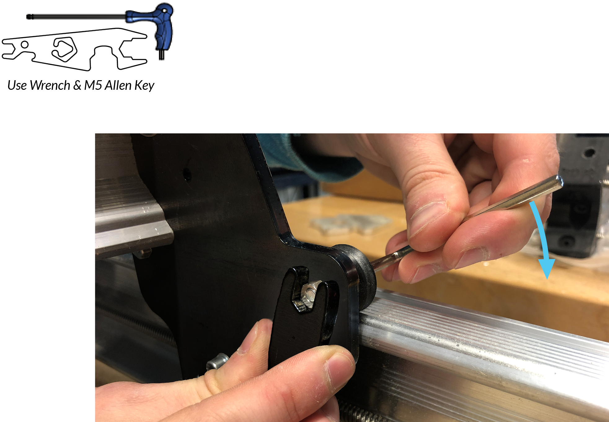
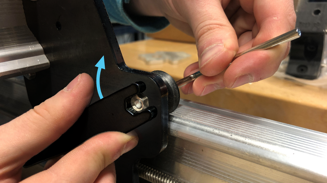
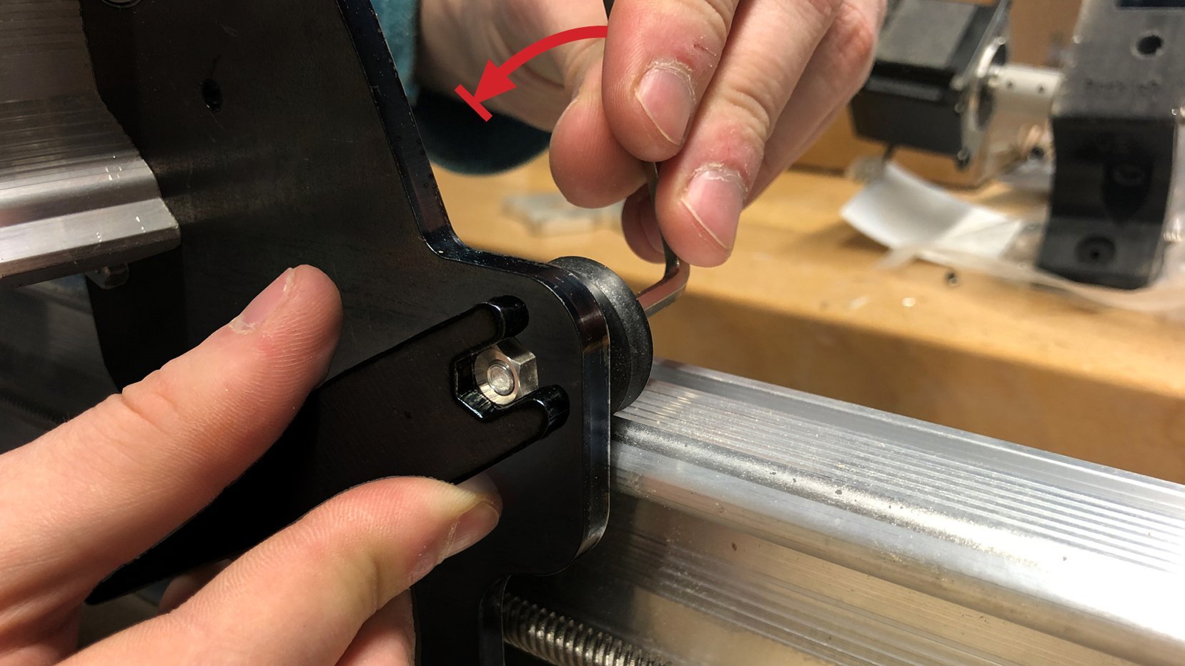
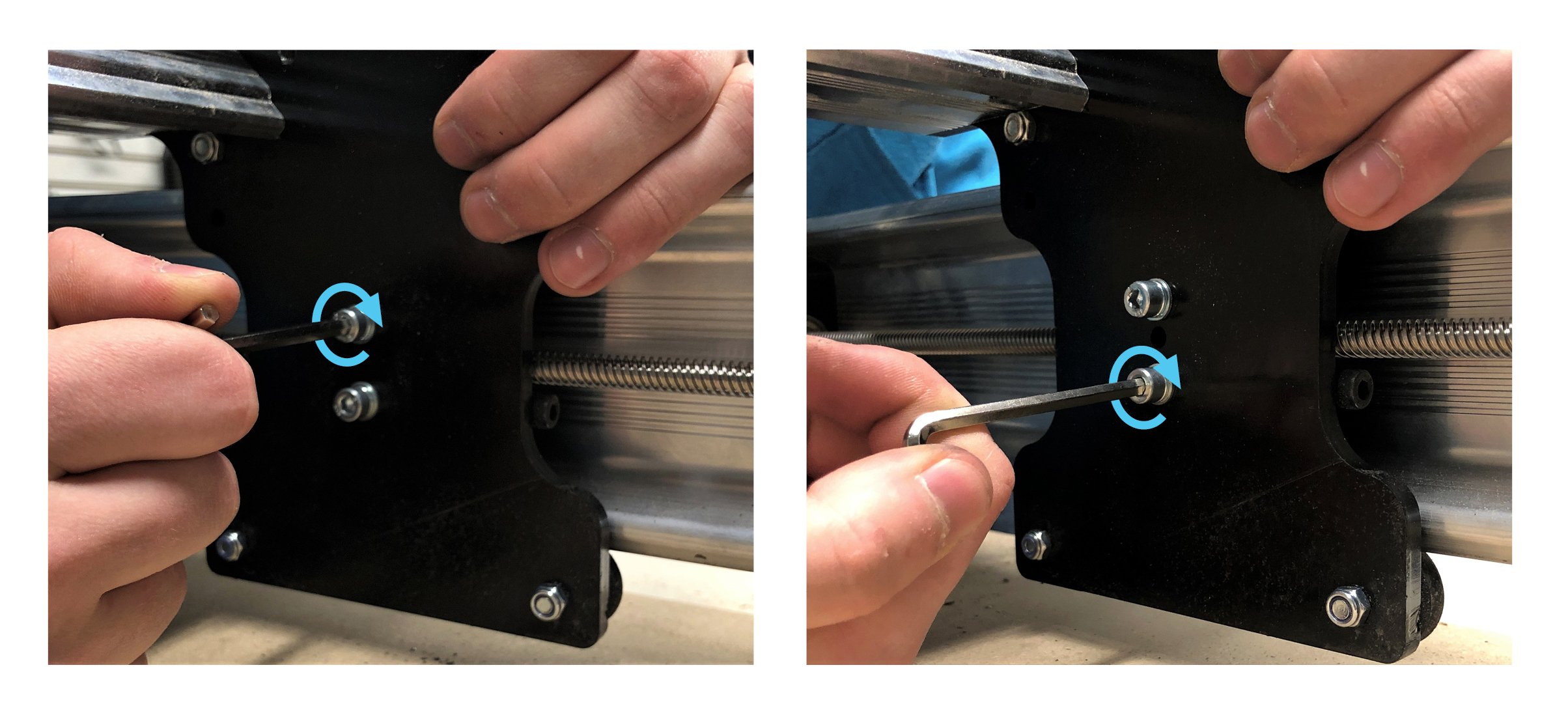
To perform ‘tensioning’ the idea is to loosen the M5 bolt with an Allen key far enough that you can rotate the eccentric nut (picture 1) all the way ‘open’ as the starting point. Then, turn the nut whichever direction you choose to close it slightly (picture 2) and re-tighten the M5 bolt with the Allen key (picture 3). For the opposite Y-axis you can access the wheel bolts by lifting up the drag chain. At this point you’ll want to check both the wheel you just tightened as well as its static wheel on the opposite side of the rail. Whichever wheel is on top will always be harder to spin, but ideal tensioning is when the lower wheel is able to barely turn when you use your fingers to rotate it.
You’ll likely need to repeat loosening, turning the nut slightly, tightening, then checking the wheels a couple times for each wheel pair until you reach the right clamping force. Take your time to slowly approach the right point rather than over-rotate the eccentric nut and put too much force on the wheels. Also, know that the wheels don’t need to be 100% perfect to have a well-operating machine so if you feel like you’ve gotten close enough then feel free to move on to the next step. If you need more help visualizing how to do this you can watch our video:
Once you’re done tensioning the wheels on all axes you should find that it’s still easy to rotate each lead screw with your hands but if you grab the steel gantry it shouldn’t move around on the rail. It might be a bit loose moving the plate back-and-forth and that’s the next step when tuning.
With the v-wheels tightened down, go around and finish bolting down the remaining anti-backlash nuts; there’s one on each Y-axis and another on the X-axis. Recall the method for doing this when you did it for the Z-axis where you alternate making a couple turns onto one bolt and then the other until they’re both tightened down fully. If you twist hard onto just one bolt while the other one is loose it can twist the anti-backlash nut and misalign it to the lead screw.
Lastly, let’s check for backlash. The term ‘backlash’ refers to the difference between where the machine thinks it is and where it actually is due to components being worn out. Since your anti-backlash nuts are brand new it’s likely that they fit really well with the ACME lead screws, this means that trying to wiggle each plate along its rail should have no looseness.
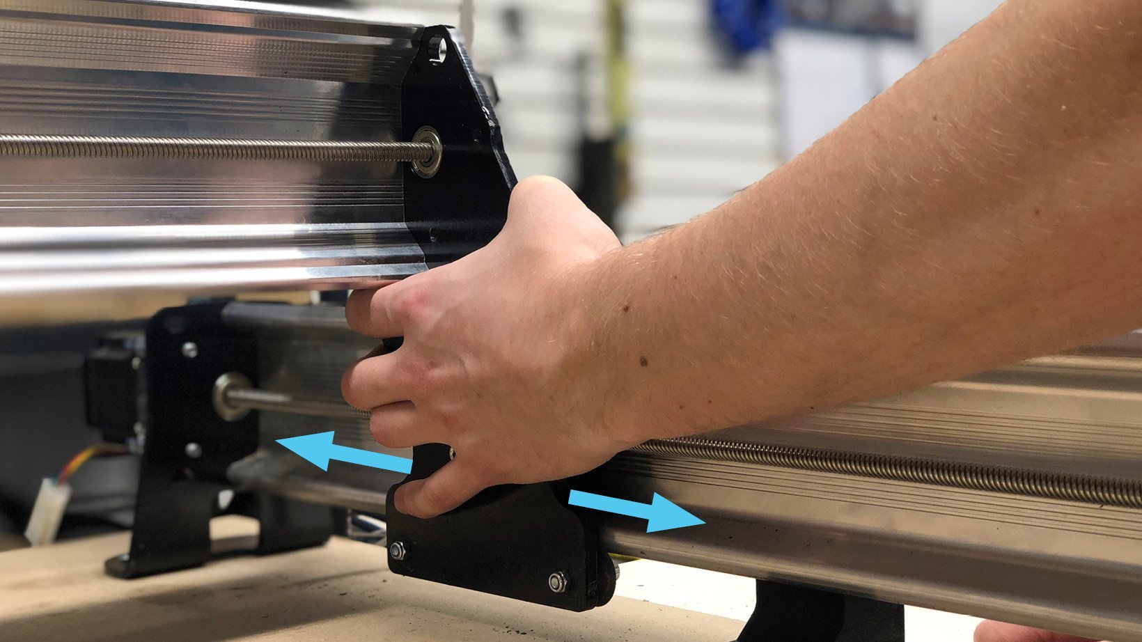
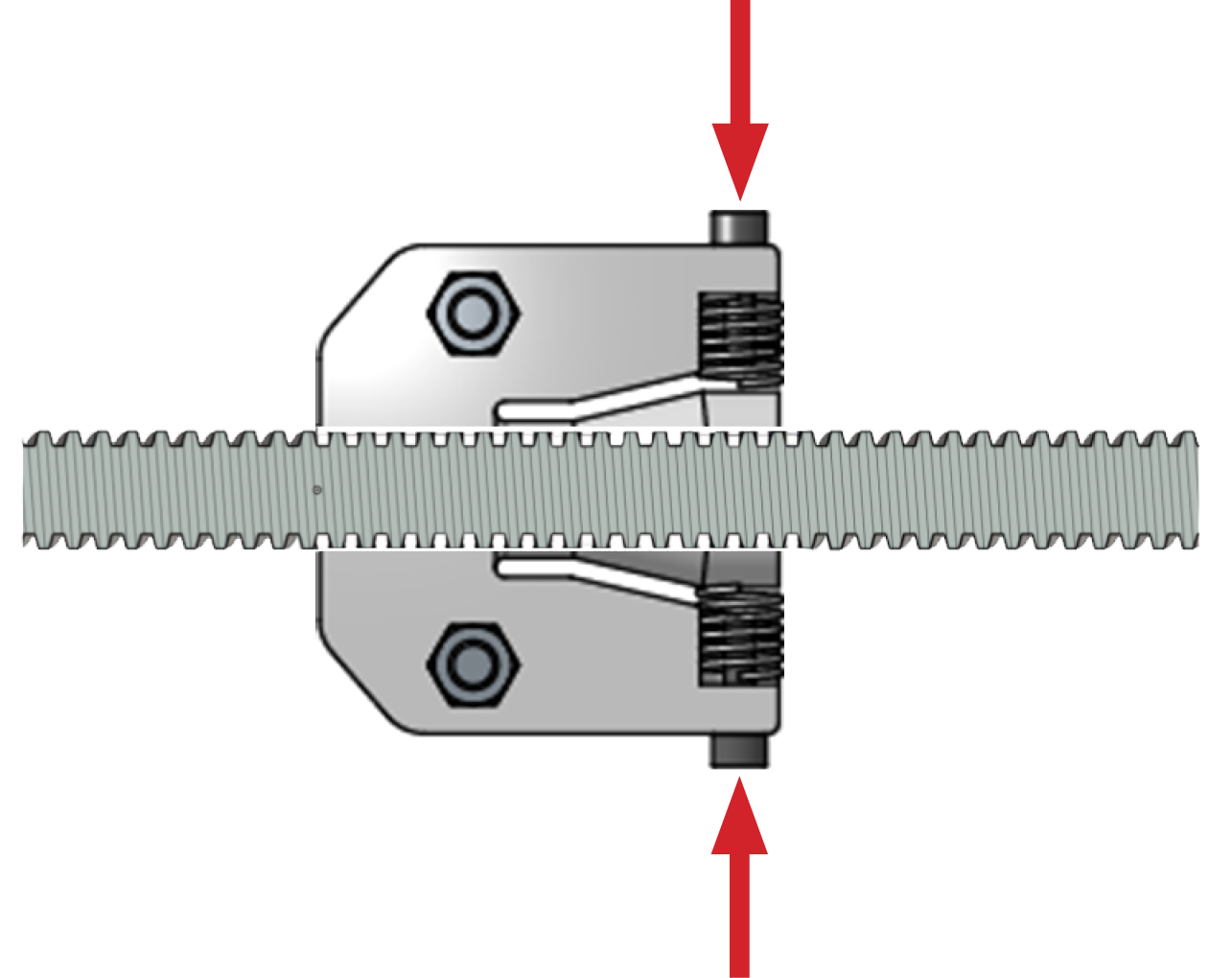
As you use your machine the nuts will wear out, but, thanks to the springs, they will self adjust and compensate for the backlash due to wear. This will keep your machine accurate for a long time. You may need to break them in a bit by moving back and forth on each axis at the beginning.
With all the tuning complete, we can move on to mounting your LongMill and starting to cut with it! If you’re planning on using your machine for especially precise cutting, also consider checking out the ‘movement tuning’ feature built-in to the calibration section of gSender: https://resources.sienci.com/view/gs-additional-features/#movement-tuning