
“Feeds and Speeds” is an all-encompassing term used to describe most of the variables that come into play when using a cutting tool to carve a material. In the hobby-sense, this includes:
- How fast the CNC moves (feed rate, plunge rate, and router/spindle RPM)
- How much material is removed (stepdown and stepover)
Figuring out how to cut materials nicely on your machine can be confusing and time consuming. Most cutting tool manufacturers spec industry-grade speeds that hobby-grade machines can’t achieve and tool information that hobby CAM software can’t use. Chatter analysis, optimizing material removal rate, tool life preservation, and more simply fall out of range for most hobby CNC’ers since they don’t do the high-load or large capacity work of business and industry. We wanted to see what we could do to help with this.
The result is a simple reference-table that you can use as a starting point for your next project. This required us to do a crazy amount of math, create internal testing patterns and procedures, run tests on all the common CNC bits and materials we could think of, and break a lot of bits along the way to hone what we hope will power up your ability to get the most out of your LongMill. We’ve also included more reading later down the page if you’re curious about the theory that drove these cutting parameters and their outcomes: ‘Cutting Theory‘.
Using the F&S Tables
Our tables try to account for the average setup you’ll have with your LongMill MK2 so that you can use the values as a jumping-off point. This is where we’ll stick a giant asterisk since despite all the work we’ve done we’ll never be able to provide guarantees against broken bits or failed projects. Woods, plastics, metals – basically any material is going to behave differently whether you’re in Canada, the USA, or Australia because of variations in natural species, manufacturing processes, temperature, humidity, and many other factors. This is the nature of CNC where it becomes more of an art than a science. All machines are different, are assembled differently, use different table setups, exist in different environments, use different cutting tools, and so forth.
Here are some other things to keep an eye out for:
- The tables (on this page and as a PDF) so far contain commonly-used hobby CNC cutting tools and materials such as soft and hard woods, common plastics, and common aluminum. If you don’t see the material you plan to cut feel free to ask around in our community for advice or what has worked successfully for others
- Suggestions for bits that do engraving, V-carving, and 3D contours will have flavours for ‘coarse’, ‘fine’, and some other use-cases but all at fixed speeds. This is because these types of cutting tools don’t tend to strain the machine so instead these options should suit what type of cutting you plan to do
- Since we know everyone will have different preferences for how they run all the other tool types on their CNC, we’ve created three options of speed/aggressiveness to suit conservative and aggressive CNC’ers alike:
Reduced Speed – Finishing or mild cutting - Use these settings when cutting fine detail to reduce material tear-out and improve surface finish and accuracy
- Useful if you’d prefer running your machine more conservatively or are just starting out using your machine
Regular Speed - For general use cutting, generally a good starting point for trying out new project materials
Full Speed – Roughing or aggressive cutting - Use these settings if you have lots of material to cut through and you’d like to speed up the process
- Ensure your v-wheels are properly adjusted when using these more aggressive settings
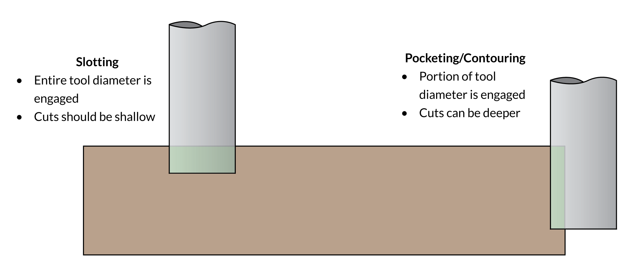
- Lastly, you’ll notice that for every tool in the tables the recommended stepdown (a.k.a. depth of cut) is larger for pocketing/contouring and smaller for slotting. This is because:
- Slotting (cutting out shapes, profiles, engraving) cuts with the full tool diameter, putting more stress on the tool and machine, thereby requiring shallower cuts
- Pocketing/contouring (surfacing, cleaning walls, clearing a specified area, 3D carving) cuts with usually less than 50% of the tool allowing deeper cuts
Plastic is a material used everywhere in our modern world with each plastic having unique properties impacting their cutting characteristics and strategy. Some are quite easy to cut like ABS, PVC, HDPE, and Delrin/POM while others like acrylic or polycarbonate can be more moderate in their cutting difficulty, similar to hard woods. Plastics also present the challenge of being more prone to melting and ‘gumming up’ the cutting bit.
For cutting acrylic we highly recommend you use cast acrylic (usually has paper backing) instead of extruded acrylic (plastic backing). Cast acrylic will always have a better surface finish compared to extruded acrylic which is significantly more difficult to cut due to its lower melting temperature.
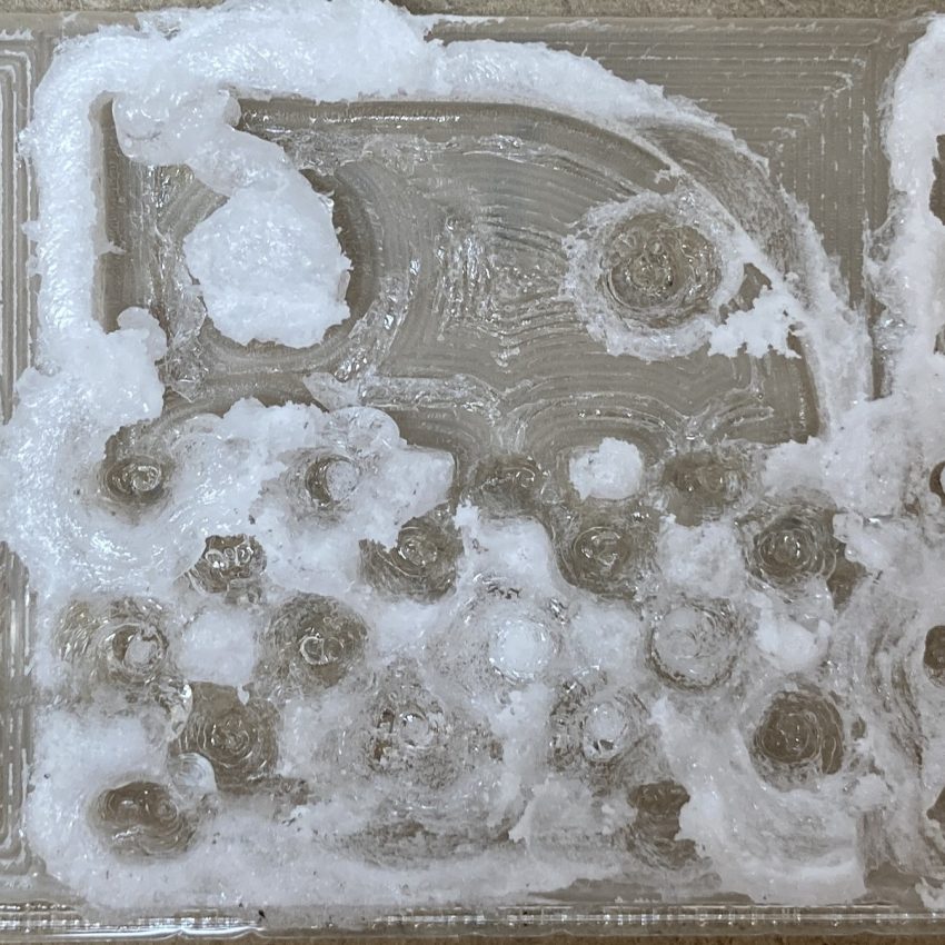
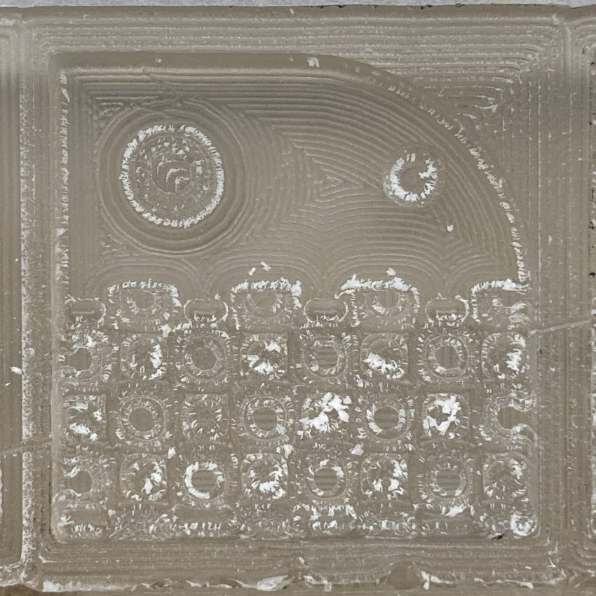
Machining on extruded (left) vs cast (right) acrylic using the same g-code
General tips and tricks for these materials are:
- A sharp cutter will help give you a nice cut and surface finish, specialized plastic cutting end mills will also give better results
- To help mitigate melting/gumming with acrylic or polycarbonate it’s advised to use upcut single flute cutting bits running at a low router speed to help clear chips; standard 2 flute end mills should work well for ABS, PVC, HDPE, and Delrin/POM
- If you find chips sticking to the cutter or melting onto the material, try increasing your feed rate or decreasing the router speed
- Specifically for acrylic, avoid taking straight plunges into the material since this will typically cause melting or fracture the material
Reduced Speed
| Cutting Tool | Feed Rate (mm/min) | Plunge Rate (mm/min) | Stepover (mm) | Stepdown - Slotting (mm) | Stepdown - Pocketing (mm) | Router Speed (RPM) | Makita Speed Dial Setting |
|---|---|---|---|---|---|---|---|
| 1/4" Single Flute Flat End Mill UC | 1600 | 800 | 2.85 | 0.6 | 1.3 | 12000 | 2 |
| 1/4" Flat End Mill UC | 2310 | 1160 | 2.85 | 0.4 | 0.9 | 10000 | 1 |
| 1/4" Ball End Mill | 2310 | 1160 | 2.85 | 0.4 | 0.9 | 10000 | 1 |
| 1/8" Single Flute Flat End Mill UC | 800 | 400 | 1.45 | 1.2 | 2.5 | 12000 | 2 |
| 1/8" Flat End Mill UC | 1600 | 800 | 1.45 | 0.6 | 1.3 | 12000 | 2 |
| 1/8" Ball End Mill | 1600 | 800 | 1.45 | 0.6 | 1.3 | 12000 | 2 |
| 1/16" Flat End Mill UC | 1130 | 570 | 0.7 | 0.4 | 0.9 | 17000 | 3 |
Regular Speed
| Cutting Tool | Feed Rate (mm/min) | Plunge Rate (mm/min) | Stepover (mm) | Stepdown - Slotting (mm) | Stepdown - Pocketing (mm) | Router Speed (RPM) | Makita Speed Dial Setting |
|---|---|---|---|---|---|---|---|
| 1/4" Single Flute Flat End Mill UC | 1830 | 920 | 2.85 | 1 | 2.3 | 12000 | 2 |
| 1/4" Flat End Mill UC | 2640 | 1320 | 2.85 | 0.7 | 1.6 | 10000 | 1 |
| 1/4" Ball End Mill | 2640 | 1320 | 2.85 | 0.7 | 1.6 | 10000 | 1 |
| 1/8" Single Flute Flat End Mill UC | 910 | 460 | 1.45 | 2 | 4.5 | 12000 | 2 |
| 1/8" Flat End Mill UC | 1830 | 920 | 1.45 | 1 | 2.2 | 12000 | 2 |
| 1/8" Ball End Mill | 1830 | 920 | 1.45 | 1 | 2.2 | 12000 | 2 |
| 1/16" Flat End Mill UC | 1300 | 650 | 0.7 | 0.7 | 1.6 | 17000 | 3 |
Full speed
| Cutting Tool | Feed Rate (mm/min) | Plunge Rate (mm/min) | Stepover (mm) | Stepdown - Slotting (mm) | Stepdown - Pocketing (mm) | Router Speed (RPM) | Makita Speed Dial Setting |
|---|---|---|---|---|---|---|---|
| 1/4" Single Flute Flat End Mill UC | 2290 | 1150 | 2.85 | 1.4 | 3 | 12000 | 2 |
| 1/4" Flat End Mill UC | 3300 | 1650 | 2.85 | 0.9 | 2.1 | 10000 | 1 |
| 1/4" Ball End Mill | 3300 | 1650 | 2.85 | 0.9 | 2.1 | 10000 | 1 |
| 1/8" Single Flute Flat End Mill UC | 1140 | 570 | 1.45 | 2.7 | 5.9 | 12000 | 2 |
| 1/8" Flat End Mill UC | 2290 | 1150 | 1.45 | 1.4 | 3 | 12000 | 2 |
| 1/8" Ball End Mill | 2290 | 1150 | 1.45 | 1.4 | 3 | 12000 | 2 |
| 1/16" Flat End Mill UC | 1620 | 810 | 0.7 | 1 | 2.2 | 17000 | 3 |
Tips and tricks for engraving or 3D carving these materials are:
- Always perform a roughing pass using a flat end mill / tapered ball end mill (with the roughing settings below) with a 0.15-0.3mm stock to leave setting before performing the finishing pass. This will dramatically improve the surface finish of your engraving and reduce the chance of melting
- If melting is still observed for acrylic, try decreasing the feed rate (this goes against the general tips we have for plastics but slowing down the rate at which material is removed is the most reliable way we’ve found to prevent melting)
- Never cut or engrave PVC with a laser, it will release toxic gasses and chemicals
| Cutting Tool | Feed Rate (mm/min) | Plunge Rate (mm/min) | Stepover (mm) | Stepdown - Slotting (mm) | Stepdown - Pocketing (mm) | Router Speed (RPM) | Makita Speed Dial Setting |
|---|---|---|---|---|---|---|---|
| 90, 60 Degree V-bit - V-Carving | 1730 | 580 | 1.8 | 0.7 | 1.6 | 17000 | 3 |
| 30, 90, 60 Degree V-bit - Fine Detail/Engraving | 1120 | 370 | 1.8 | 1.1 | 2.4 | 22000 | 4 |
| 1/4" - D1/16" Tapered Ball End Mill - Coarse | 700 | 350 | 0.24 | N/A | 0.4 | 10000 | 1 |
| 1/4" - D1/16" Tapered Ball End Mill - Fine | 1000 | 500 | 0.08 | N/A | 12.7 | 10000 | 1 |
| 1/8" - D0.5mm Tapered Ball End Mill - Coarse | 2000 | 1000 | 0.15 | N/A | 0.25 | 10000 | 1 |
| 1/8" - D0.5mm Tapered Ball End Mill - Fine | 3000 | 1500 | 0.04 | N/A | 25.4 | 10000 | 1 |
| 1/4" Ball End Mill - Finishing | 1680 | 840 | 0.13 | 1.4 | 25.4 | 22000 | 4 |
| 1/8" Ball End Mill - Finishing | 1030 | 520 | 0.13 | 2.3 | 25.4 | 27000 | 5 |
PDF Tables
Handy for printing out as a quick reference to keep on your computer or by your CNC and available in both imperial and metric units.
 Feeds & Speeds – Metric |
Feeds & Speeds – Imperial |
Tool Library files
FAQ
Are you ever going to provide feeds and speeds for material X?
We’ve tried to cover most common/popular materials and hope to expand our feeds and speeds to include other materials in the future, but we can’t cover everything. Less popular materials such as FR4, carbon fiber, and steel can all be cut, but aren’t very popular. If there’s a particular material you’d like us to provide, feel free to contact us and let us know.
Will these feeds and speeds work with the cutting bit I got from X?
As long as the important cutting bit geometry is the same, probably. There is a misconception in the hobby CNC router space that different sources of cutting bits will perform completely differently. Some may be sharper or higher quality than others but most will perform fairly similarly in common materials such as woods.
The router speed/RPM you suggest for this bit is much slower than I normally use, isn’t faster always better?
The router speed/RPM is determined by the geometry of the bit, type of material, and feed rate which might end up being slower than you would expect. This is further discussed in the topic of chip load. It’s intuitive to think that cranking up your router speed will help cuts come out better – and to some extent it might – but an appropriate router speed is one that generates chips not too large (overloading the bit) and not too small (causing burning).
I’m used to cutting much faster than what these recommended feeds and speeds are, am I doing something wrong?
When cutting softer materials, you might find that you can cut much more aggressively than what we recommend. This is because the recommended feeds and speeds are more based around retaining good cut quality, and less around cutting as fast as possible. In our own testing, soft woods can actually be cut about twice as aggressively as what is recommended, but you’ll likely encounter losses in quality, splintering/splitting, and even large chunks of wood stripped out depending on the wood grain.
Am I going to wear out my tools faster by cutting with more aggressive settings?
Technically, yes, but in practice no. Some bits may be sharper than others from the factory, but you can expect tools to perform about the same throughout their lifespan regardless of how aggressively you run them. The main detriment which causes premature tool wear is using an inappropriate chip load.
Are you ever going to make a downloadable tool database for X CAM program?
Many CAM programs don’t have the functionality of importing and exporting tool databases/libraries, so we focused on two popular CAM programs which do.
My CAM software only allows me to input my stepover as a % value, not in mm or inches. What should I use?
Almost all of the suggested stepover values are based on a 45% stepover value so you can use this for any software which requires this value. You might even find that your CAM software is already defaulting to this value.
Why are there no cutting parameters for cutting X material with X cutting bit?
If you can’t find specific cutting parameters for a particular material-bit combination, it’s likely because this is a material-bit combination we cannot advise. Some examples of inadvisable combinations might include cutting aluminum with a corn cob end mill, or using a surfacing bit on acrylic.
Why is my machine struggling to cut even when using the ‘Reduced’ cutting parameters?
These cutting parameters were developed to be used on the average LongMill MK2 without overstressing the machine, if yours doesn’t seem to be keeping up at these parameters it might be your machine’s way of telling you that something is loose, worn, or misassembled. Check out our page here covering tuning, maintenance, and checks for loose components.
Can I use these feeds and speeds on my non-LongMill machine?
Hobby CNC routers can vary greatly in terms of their rigidity and capabilities, so this will depend. If you’re using these on an industrial machine, these cutting parameters might be a bit conservative but will work just fine. If you’re using these on a slightly less robust machine, you might want to dial back some of these settings and proceed with caution. Either way, use your best judgment and adjust accordingly.
Cutting Theory
There are two schools of thought on how to select cutting parameters for a hobby CNC machine; calculate all parameters based on theoretical equations, or trial and error based on cut quality and perceived machine strain. An argument can be made for both of these approaches so it’s best to take any theoretical method with a grain of salt and explore how changing certain parameters will affect your machine and projects experimentally. That being said, it’s well worth understanding some of the relationships between different cutting parameters which is why we’ll delve into the theory side of things.
It’s important to understand the main goals in how one goes about deciding on a certain set of cutting parameters. These are typically:
- Making sure the cutting bit is creating healthy sized chips – not rubbing and creating dust
- Ensuring the machine is cutting at a pace and depth that both the user and machine are comfortable with
We can break down two metrics for targeting both of these goals – chip load, and material removal rate (MRR). Simply put, we’re concerned with how big each individual chip of material is when cut and how much material is removed in a given amount of time. Both of these metrics depend highly on the material you’ll be working with which is what makes choosing cutting parameters so confusing.
Chip Load ✂️
Chip load describes the size of each individual chip that is being cut by a single edge of your cutting bit.
This is a very sensitive parameter. If too small, the chips reduce in size to become dust which will wear out the bit and heat up causing burning. If too large, the chips become larger which results in the cutting bit being overloaded and unable to clear the chip out of the cut. The effects of chip load on cut quality can be seen below.

To calculate chip load there’s a simple formula shown below. Since we usually know the number of flutes our cutting bit of choice has, we can modify either feed rate or router speed/RPM to reach the chip load we want. In some cases the speed of the router might not be fast or slow enough to reach the desired chip load so we could change the cutting bit to have more or less flutes to accommodate that. Another approach would be to change the diameter of the bit, thus calling for a different chip load and making it more feasible for the router speed or feed rate you have available.
Chip Load = ( Feed Rate ) / ( Router Speed x # Flutes )
For example, if we’d like a chip load of 0.0031″, we can run a 2 flute end mill at a speed of 17000 rpm and feed rate of 105.4 inches/min (2677.16 mm/min) to achieve this.
Chip Load = 0.0031" = ( 105.4 ipm ) / ( 17,000 RPM x 2 Flutes)
Many charts exist which attribute a certain chip load value to a given cutting bit size and material. For our own purposes we’ve attributed a chip load per unit diameter to the common groups of materials as shown in the table below.
| Softwood, MDF | Hardwood | Plastics | Aluminum | |
| Chip load per unit diameter | .025″ per inch | .025″ per inch | .03″ per inch | .0125″ per inch |
| Chip load for 1/16″ diameter end mill |
.0016″ | .0016″ | .0019 | N/A |
| Chip load for 1/8″ diameter end mill |
.0031 | .0031 | .0038 | .0016 |
| Chip load for 1/4″ diameter end mill | .0063 | .0063 | .0075 | .0031 |
Material removal rate ⛏️
Material removal rate asks the question “how deep can I cut?” Now that we have our targeted chip load and calculated feed rate and router speed we can move onto figuring out the last pieces of the puzzle: depth of cut and stepover.
Naturally we can assume that the more material we cut in a given time, the more strain is placed on the machine and router. If we can quantify how much material is getting removed in a given amount of time, we can aim to keep this within a reasonable amount – this is what the material removal rate metric does. The standard units for material removal rate are in volume per minute – either inch3/min or cm3/min.
Shown below, the formula for material removal rate depends on feed rate, cutting width, and cutting depth. Cutting width will depend on whether you’re slotting (cutting out pieces of things, cutting lines and shapes, etc.) or pocketing (making large holes, cutting out pockets, bowls, etc.) since the full width/diameter of the cutting bit will either be fully engaged (slotting) or partially engaged (pocketing).
Material Removal Rate = Feed Rate x Cutting Width x Cutting Depth
For slotting the cutting width will be fully engaged, meaning our cutting width or width of cut (WOC) will be equal to the tool diameter (ie. WOC = 0.25″ if using a ¼” bit).
For pocketing our tool will only move over by some distance between passes, typically this distance should be about ~45% of the width of the cutting bit (ie. WOC = 0.25″ x 45%=0.1125″ if using a ¼” bit).
The illustrations below show the use of a tool in a high depth of cut, low width of cut scenario (left), as well as low depth of cut, high width of cut scenario (right). With the feed rate constant between these two cuts, they’ll both be removing the exact same amount of material in the same amount of time.
-
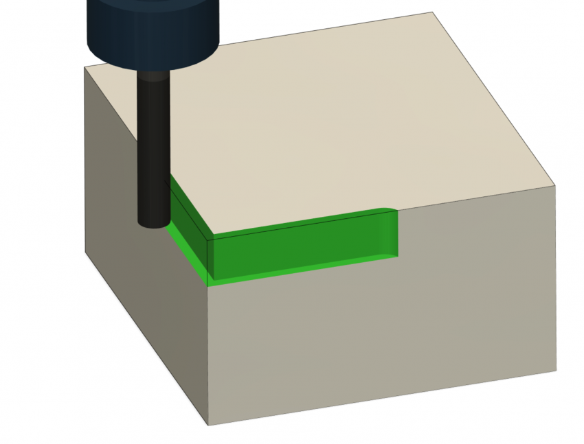
- 10mm DOC, 2mm WOC (pocketing/contouring)
-
- 3.15mm DOC, 6.35mm WOC (slotting)
Since we know our desired feed rate (from our chip load calculation) and cutting width (depending on the cutting operation), we can calculate what our cutting depth should be if we’d like to keep our material removal rate below some reasonable amount. At this point, we’ve now gotten all of our cutting parameters necessary for setting up a cutting operation.
Theory Review 📖
As mentioned above, one of the most useful aspects of machining theory applied to hobby CNC is not the actual calculation of parameters – but rather the relationships we can understand between different cutting parameters.
We’ll do a quick review on how some cutting parameters might affect other outcomes:
- Increasing router speed/RPM will make chips smaller and become dust if too fast (not a good thing)
- Increasing feed rate will make chips larger, and also put more strain on the machine
- Increasing feed rate, and increasing router speed/RPM will keep chip load the same and allow you to cut material faster
- Using a cutting bit with more flutes will decrease chip load, unless router speed is increased accordingly, or feed rate is decreased accordingly
- Decreasing cutting width/WOC will allow you to cut deeper with the same amount of strain on the machine
- Using a larger cutting bit means your targeted chip load should be greater, meaning your router speed/RPM should be lower
3D carving/reliefs ⛰️
While the theory presented above holds true for any type of machining, there are a few additional constraints that we should be aware of when 3D carving.
The first constraint to pay attention to is cutting width/stepover. This is a variable that we can typically change to control the rate of material removal but in 3D carving it’s directly tied to surface finish and is typically a small number (~5-15% depending on the size of the bit).
")
When a ball end mill carves in several straight, parallel passes it leaves behind small amounts of material in the form of ridges – these are known as ‘cusps’. These cusps are the reason for the increase in detail/resolution with a lower stepover; as shown in the photo below, a larger stepover means larger cusps, while a smaller stepover means the cusps continue getting smaller until they’re imperceptible to the human eye. Obviously, with lower stepover, this means a greater number of passes, and a much longer total project time. You’ll need to decide how much detail you need, and how long you’re willing to run the project for. For example, for carving a 2″x2″ relief, you’ll probably want to use a low stepover amount such as 5-8% since this project won’t take more than an hour. If you we’re carving something much larger, you might want to set your stepover much larger and forego finer detail for a faster overall project time.
Cutting depth is the next variable to consider and in relief carving this is again something that you do not have much control over. This is because the tool will need to follow the contours of your 3D model which can vary considerably in depth.

The implications of the two constraints above are that tools will tend to be underutilized (removing too little material) on the shallow parts of the relief and struggle on the deeper / steeper parts (removing too much material). For wood based materials, you’re less likely to exceed the tool’s material removal capabilities on even the deepest parts of your relief without running into other constraints in your machine such as feed rate. On harder materials such as acrylic / aluminum however the spikes in material removal is a much bigger concern and is why roughing (with a very shallow depth of cut and minimal stock to leave) is a prerequisite for success.
