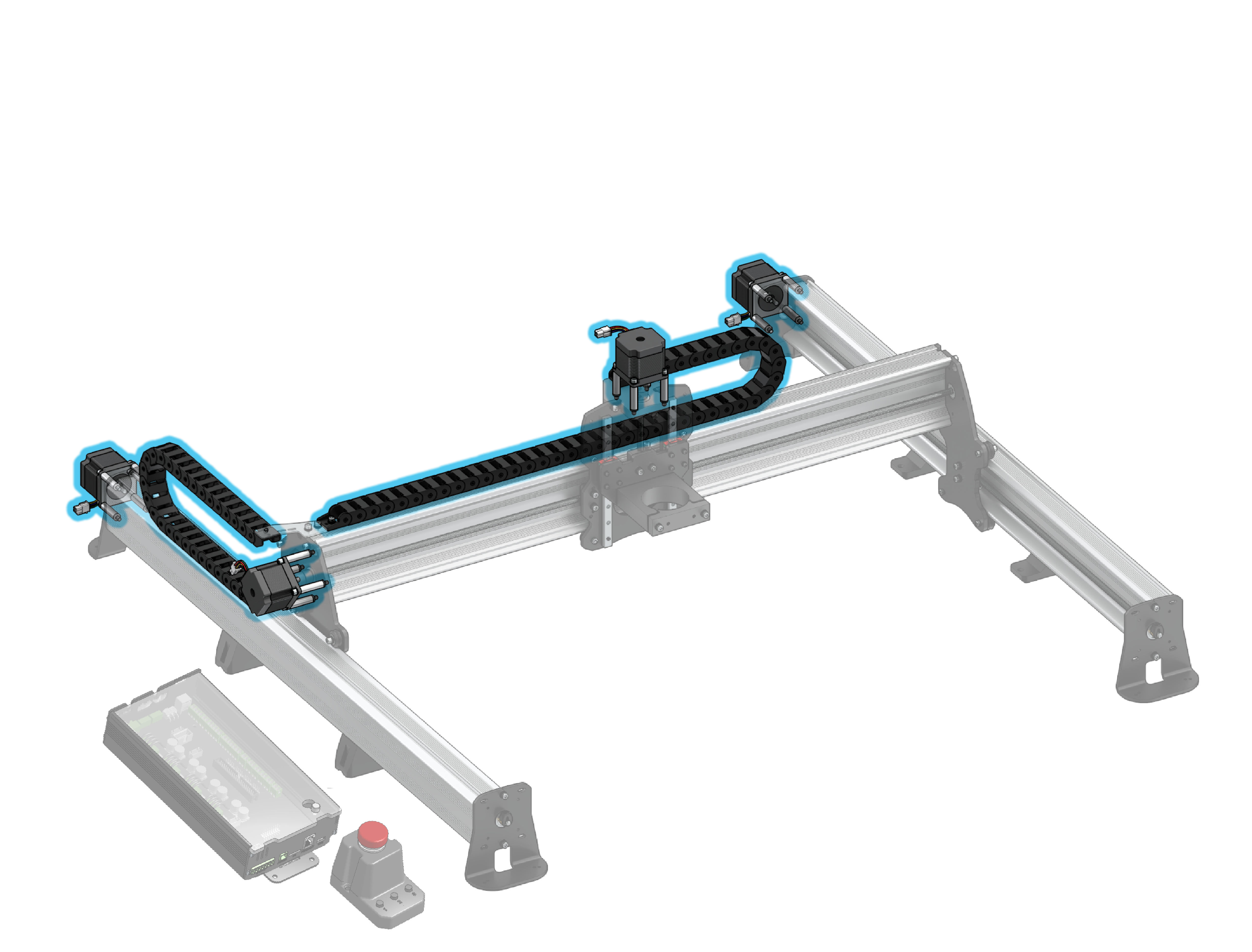
Stepper Motor Mounting
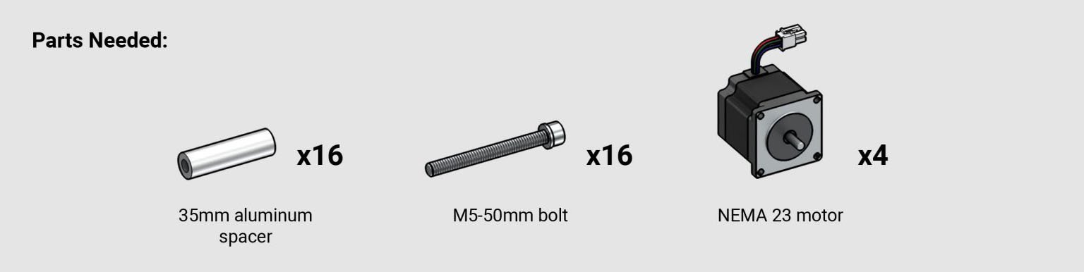
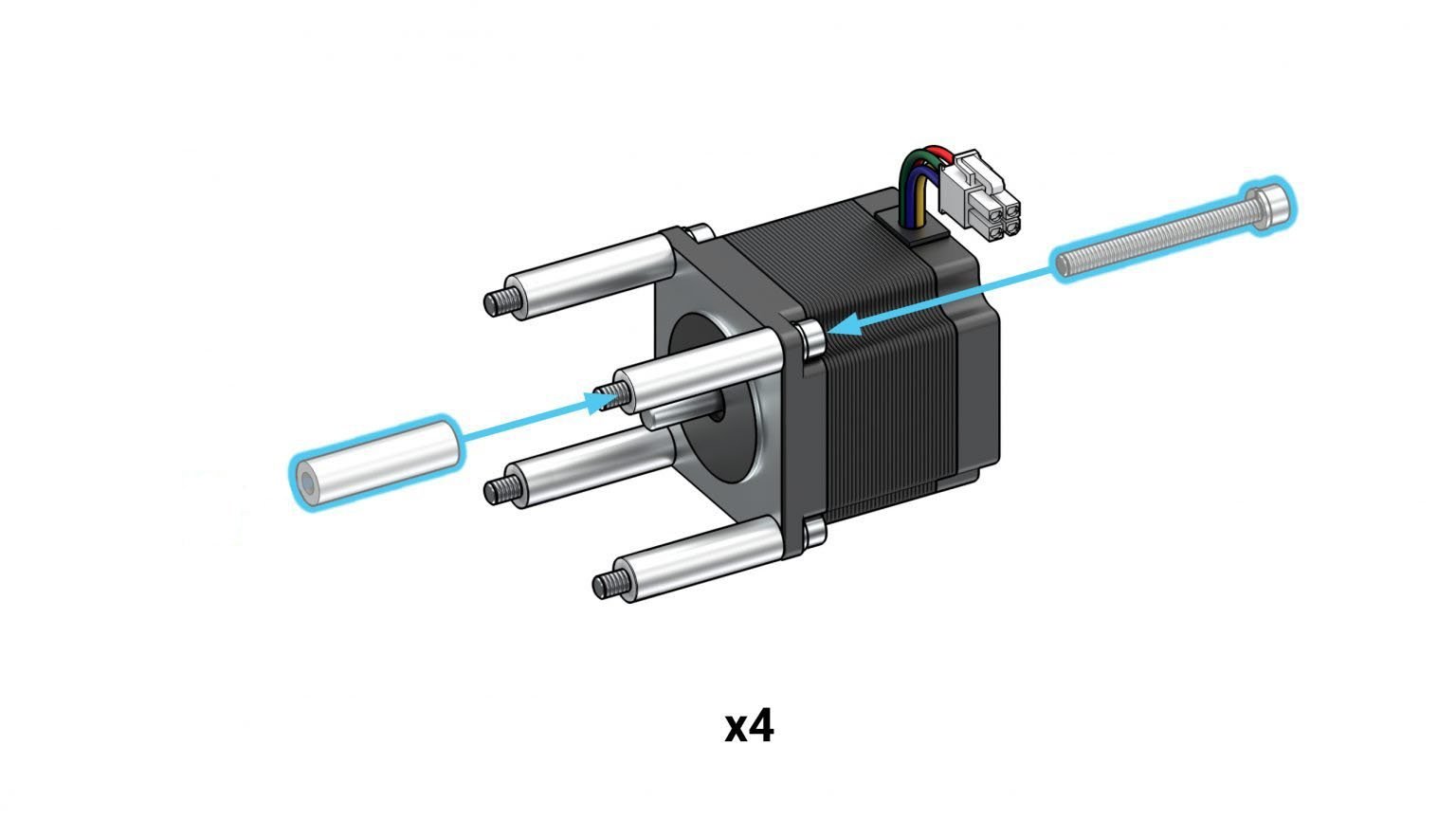
You’re really making your way along, celebrate with a friend and a cold drink!! Look back to the yellow bag and grab the 35mm spacers, M5-50mm bolts and also grab the NEMA 23 stepper motors out of the motor box. You’ll be inserting four M5-50mm bolts into the four holes on each motor along side the aluminum spacer. These assemblies will attach to each axis of the machine. Note: Earlier versions of the LongMill shipped with Nylon washers. If your machine has these washers, install the washers between the 35mm spacer and the metal gantry plates and feet.
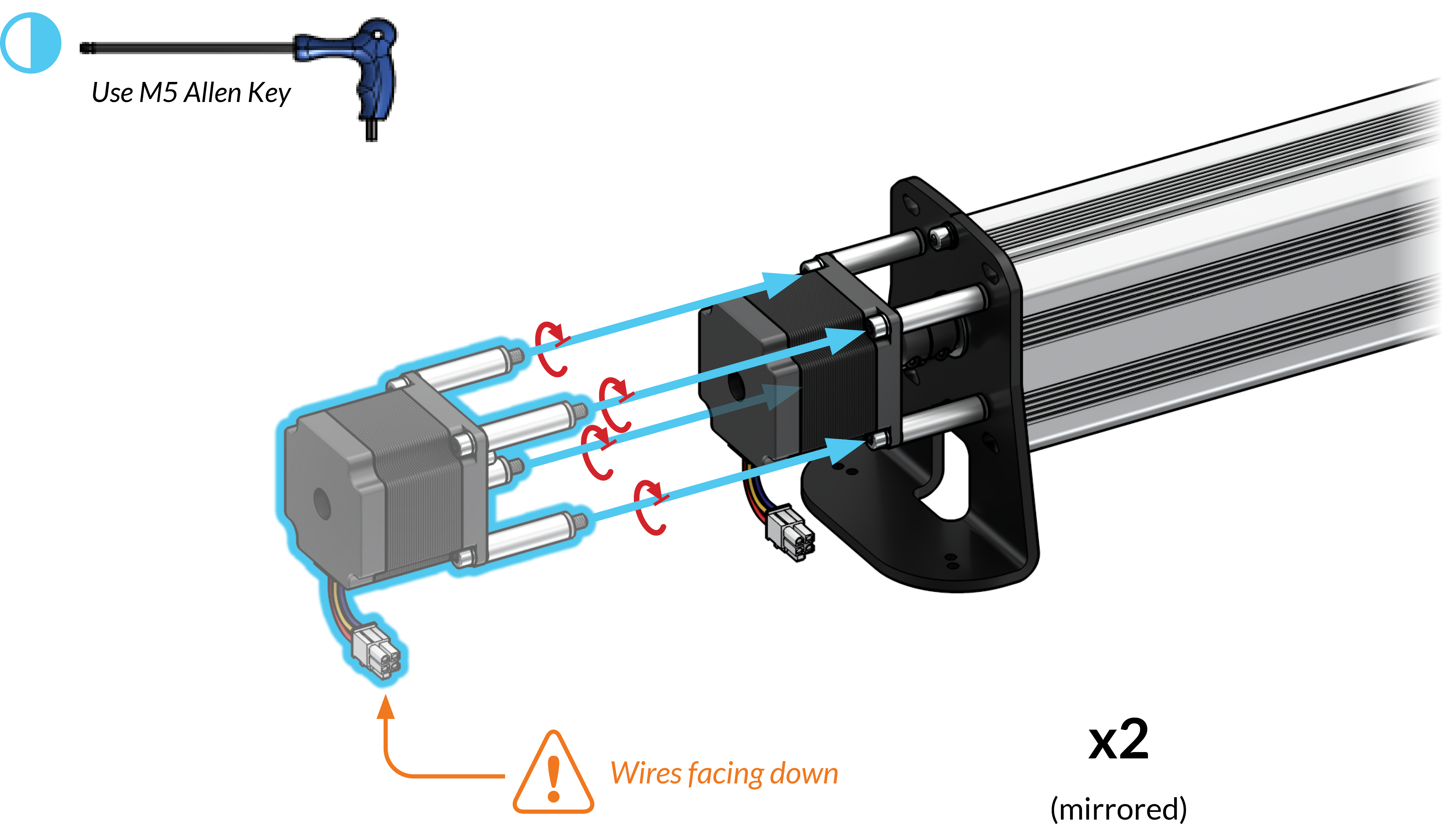
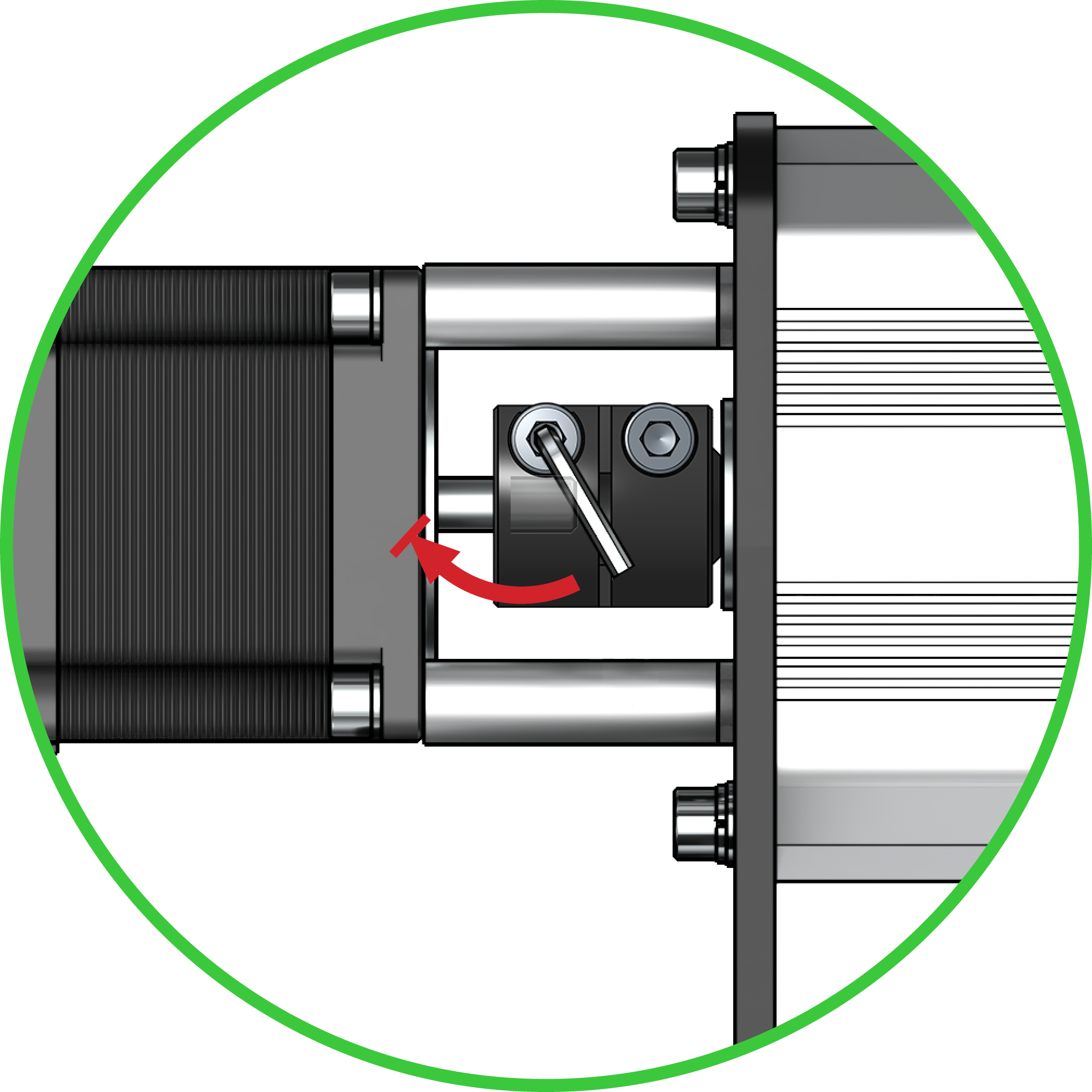
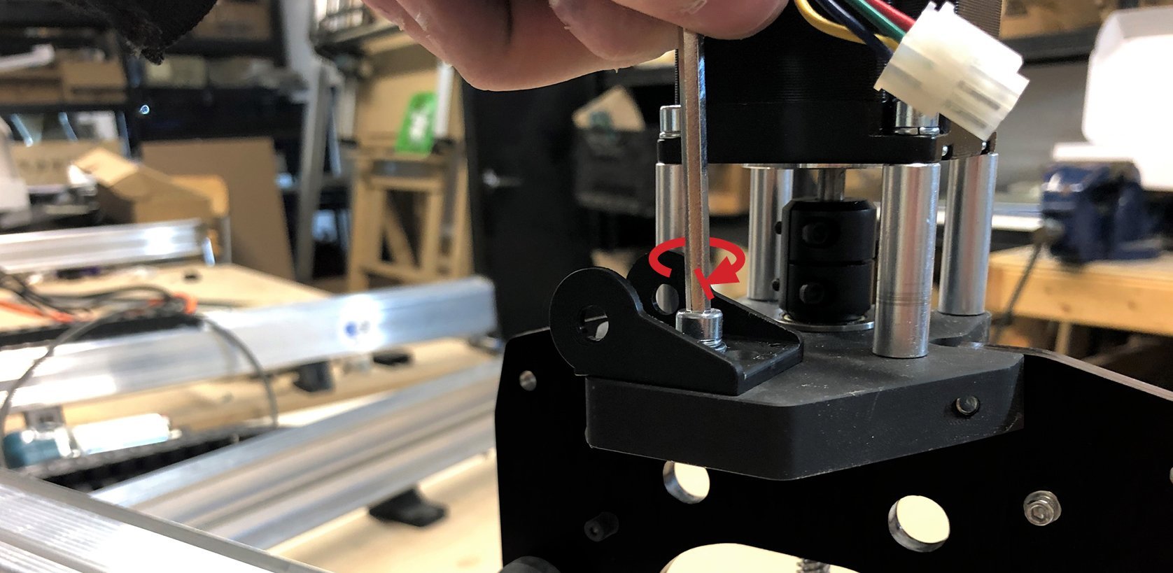
For both Y-axes, position a motor assembly at the back foot making sure the motor wire faces down. Slide the motor shaft into the coupler, then tighten all four M5-50mm screws into the foot. Once the motor is secure, tighten the set screw on the motor side of the coupler (pictured).
If everything has come together well so far, you should be able to now check that the lead screw can spin relatively easily. If you find that the motor shaft doesn’t fit into the coupler it’s likely that you tightened the motor-side set screw earlier on and have now deformed it. There is a chance for fixing this: take the motor-side set screw out of the coupler and insert anything thin like a box knife, putty knife, or paint scraper into the vertical slot of the coupler. Then screw in the set screw from the opposite side until it hits the inserted object. Rotate it against the object a couple turns to open up the slot again, then back the screw out again, remove the object, and reinsert the screw back to where it should be.
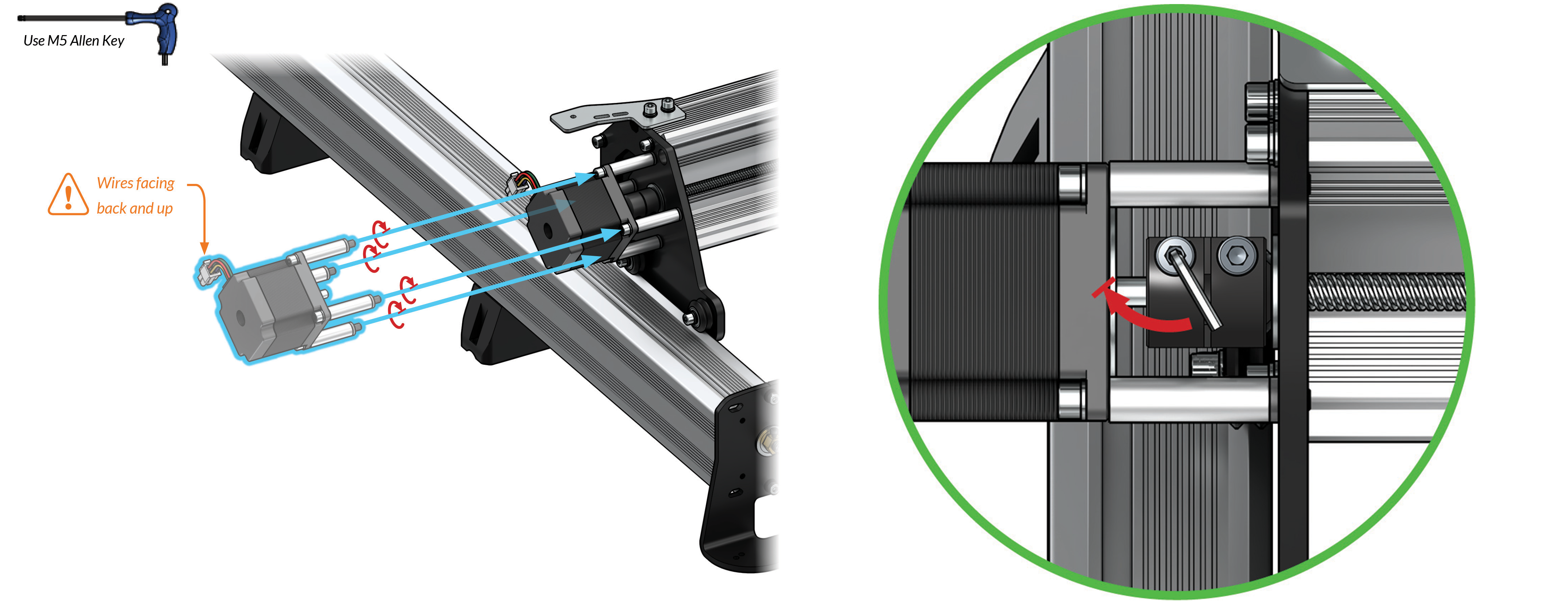
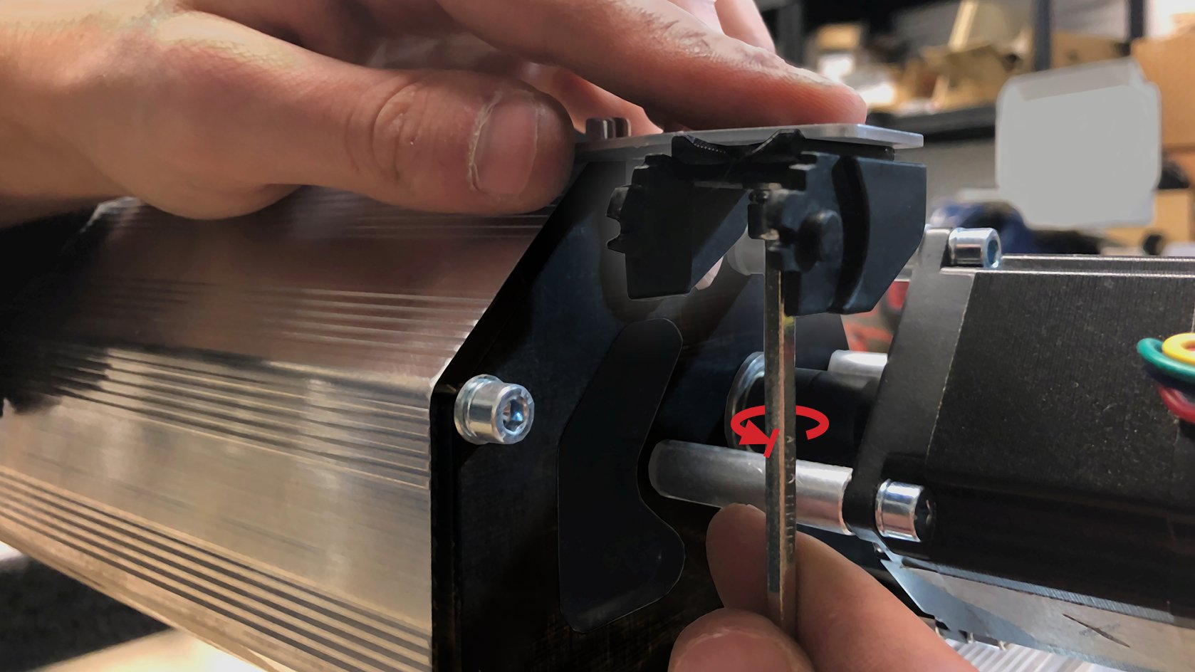
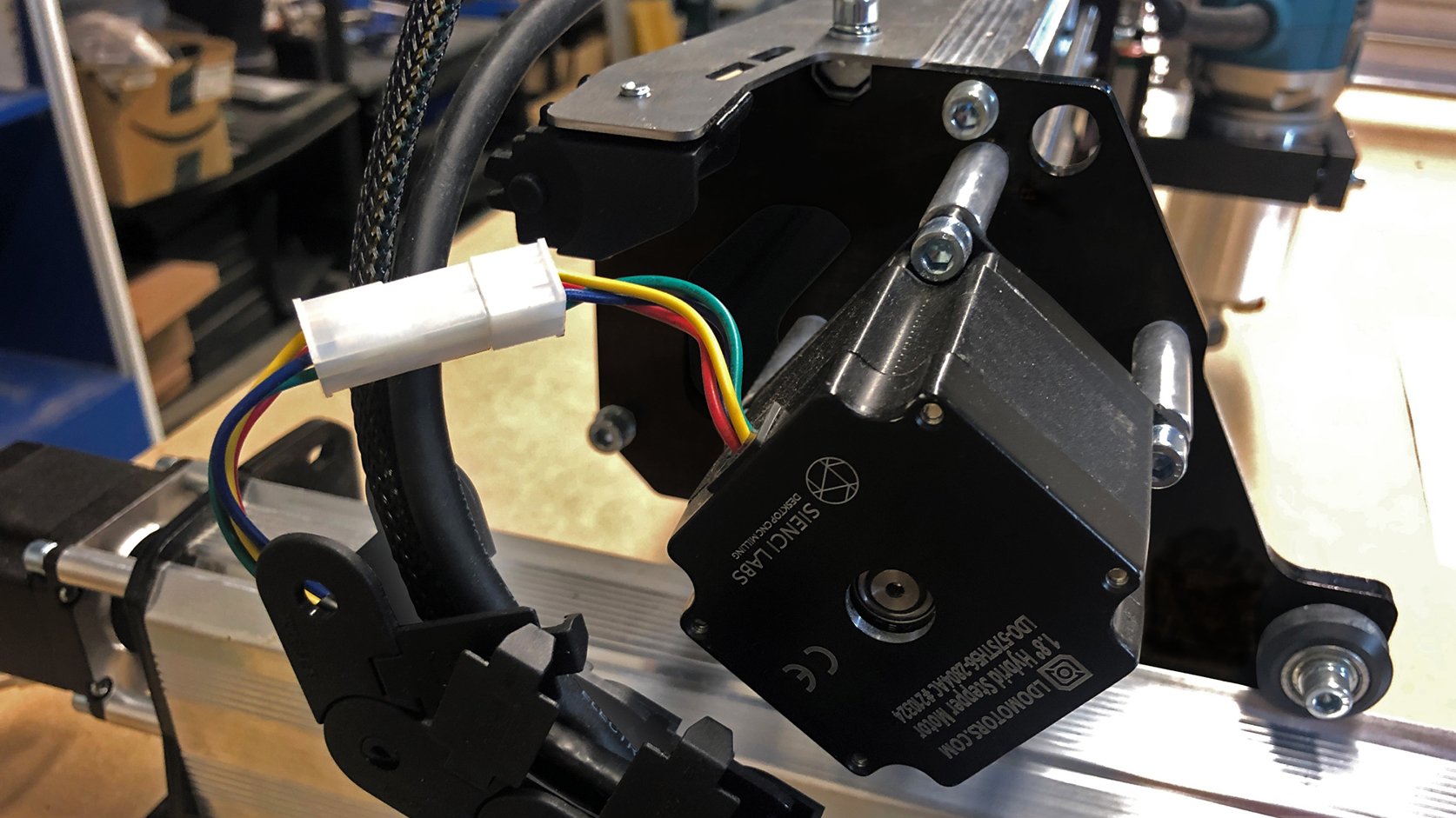
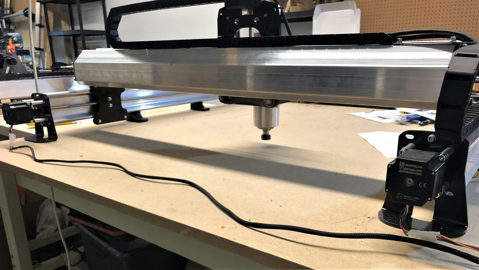
Bring a motor assembly to the left Y-gantry plate making sure the motor wire faces back and upwards (pictured). Slide the motor shaft into the coupler, then tighten the four M5-50mm bolts into the gantry. At the coupler, tighten the set screw at the motor side and ensure the lead screw can spin without excessive force. ![]()

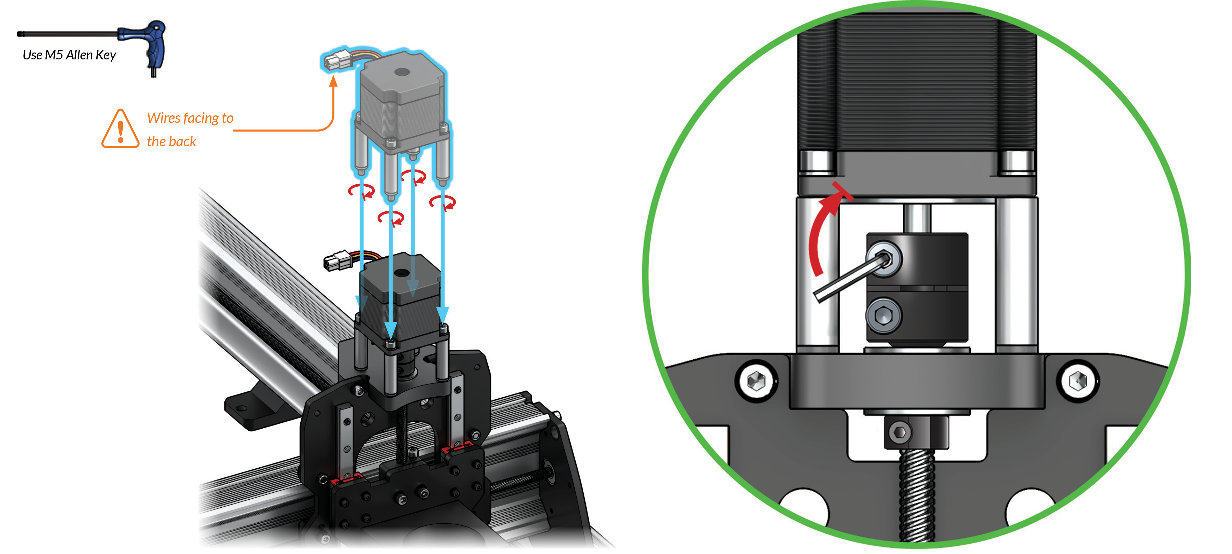
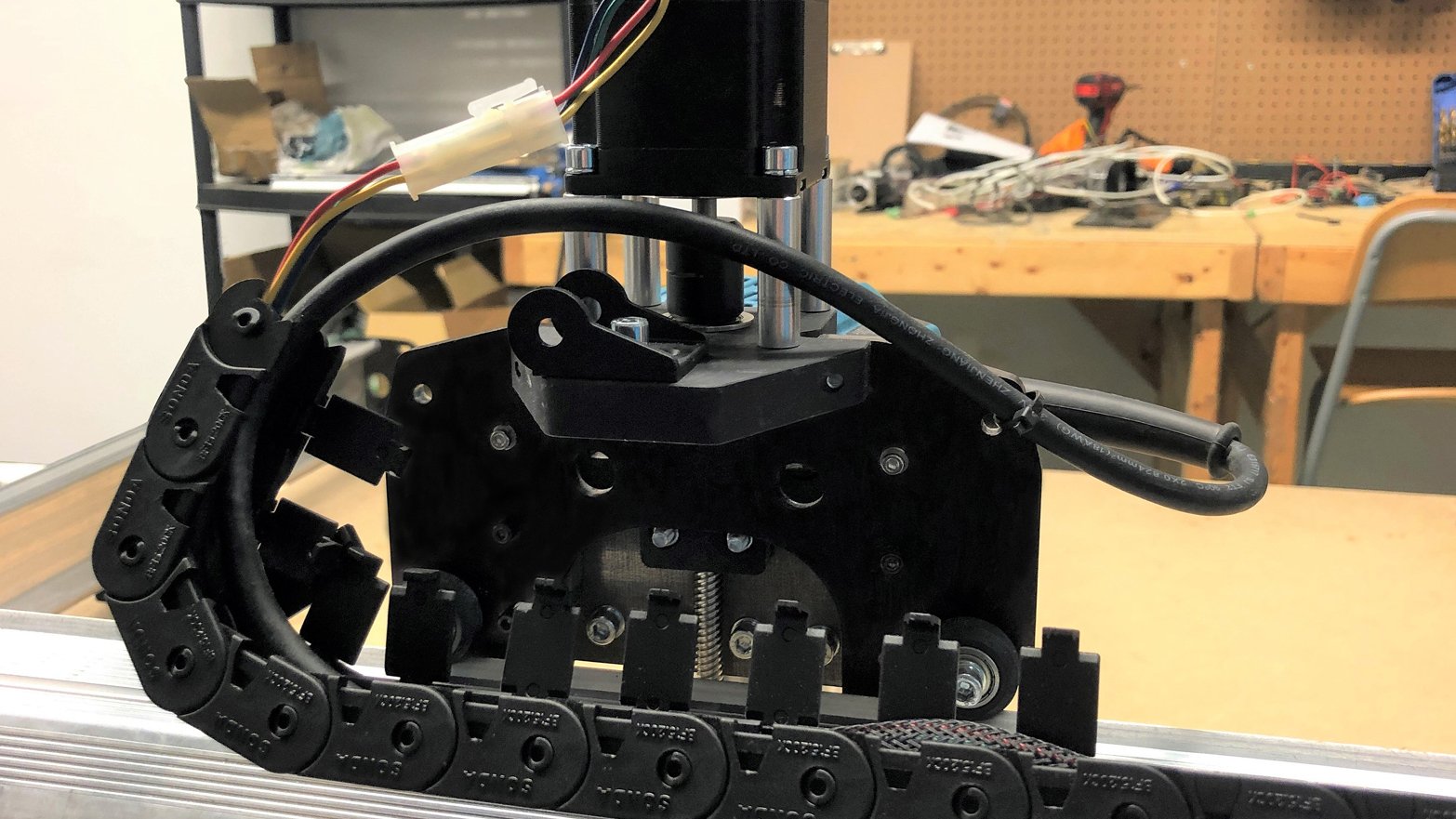
Bring the last motor assembly to the Z-axis motor mount making sure the motor wire faces backwards. Slide the motor shaft into the coupler, then tighten the four M5-50mm bolts into the motor mount. At the coupler, tighten the set screw at the motor side and ensure the lead screw can spin without excessive force.
Attaching Drag Chain Ends
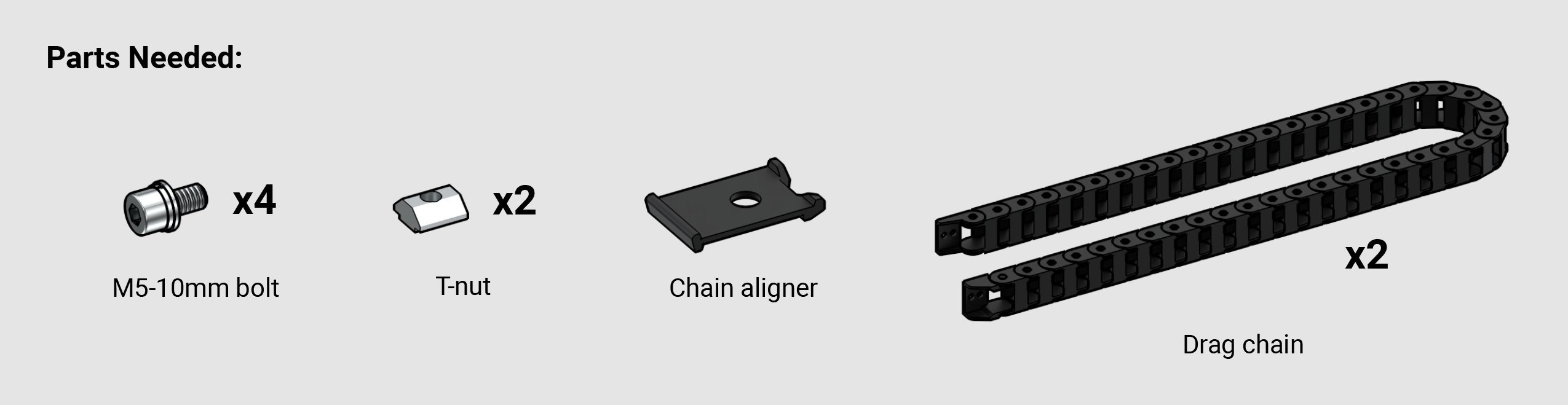
We will now be installing the drag chains which can be found in the long rail box inside the Y-axis rails. These contain and guide the wires on the LongMill so they aren’t in the way during cutting. They also keep wires from wearing out from bending or being cinched around corners.
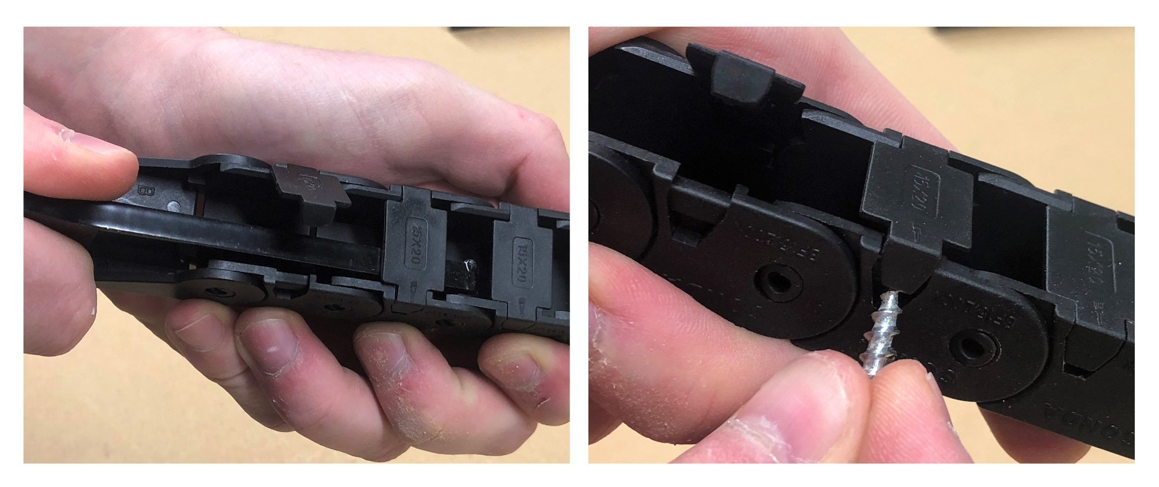
Start by un-clipping all the drag chain clips using a flat head screwdriver or anything else sharp like a wood screw underneath the clip tabs. These hold the wires into the chain but can open or be completely removed, giving flexibility to add or remove wires on your machine when needed. If you’re struggling with this the LongMill wrench also has a taper that can help you open them.
We recommend permanently removing every other clip if you plan on adding more wiring in the future since accessing the wire will take half the time and the chains will still work fine. Stick the extras into a baggy to save for later if you wish.
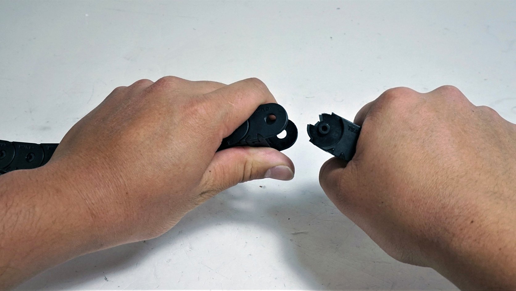
Now, remove the end links from both sets of drag chains. For the pin-type link (left picture), squeeze it together then twist and pull to disconnect it. For the hole-type end link (right picture), pull on one side of the link then twist it away to separate it. A flat head screwdriver or thin shim can also be handy for this, just be careful not to cut yourself.
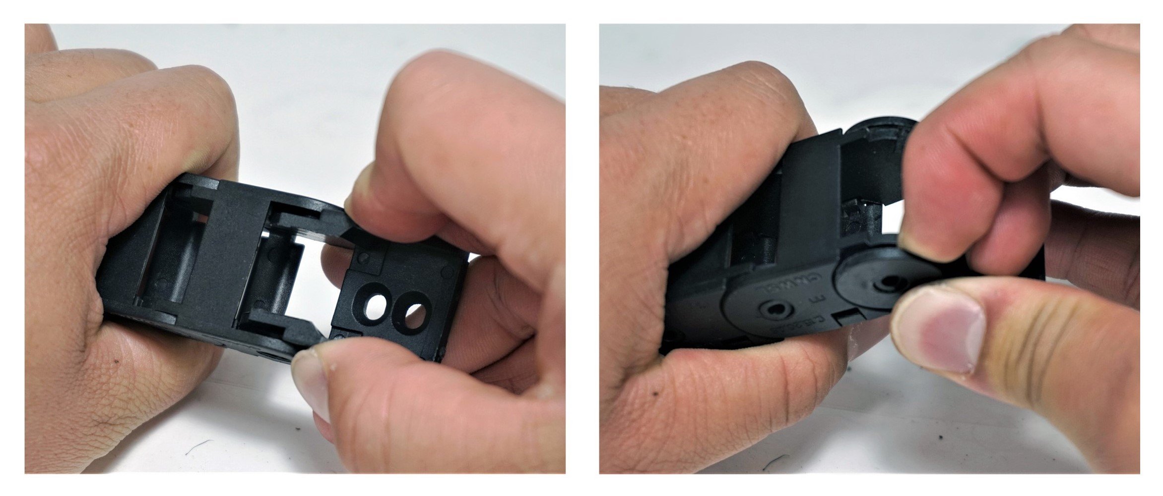
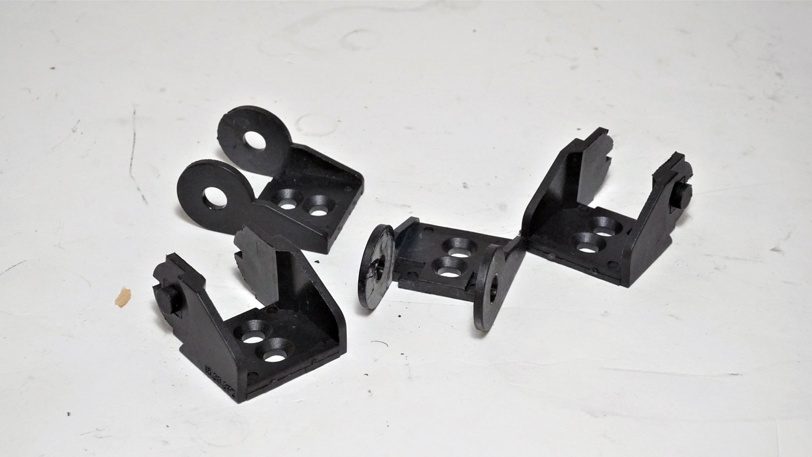
Do this for all four end pieces, two hole-types and two pin-types, and set them aside.
Grabbing the bag of t-nuts and M5-10mm bolts, we will attach these end links to the machine starting with the left Y-axis. Slide a t-nut onto the Y-axis rail through the hole in the front foot.
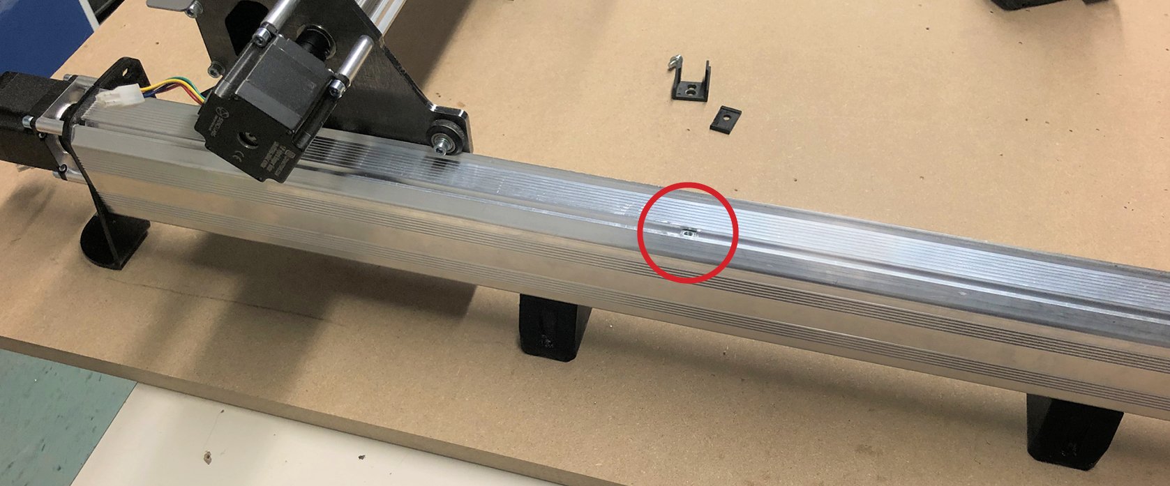
You’ll want to position it a little further back than halfway on the rail for both machine models (30×30 pictured).
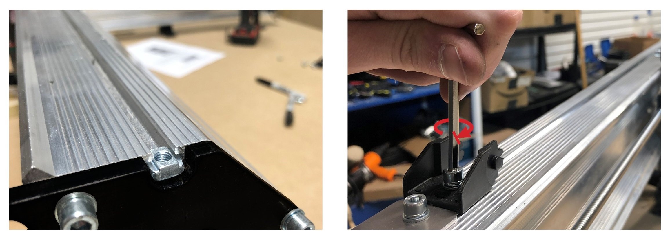
Once in position, use an M5-10mm bolt to fasten a hole-type end link in place with the M5 Allen key (pictured).
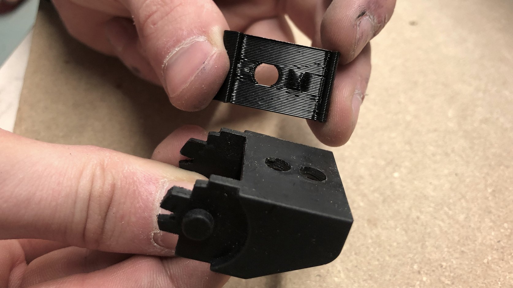
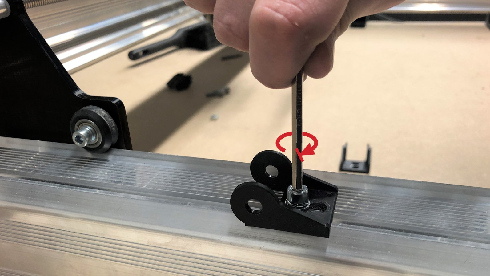
Now get a pin-type end link (pictured) along with the 3D printed chain aligner from the yellow hardware bag to mount the other end of the drag chain. The printed aligner has a nub that will align to a hole in the end link (pictured).
These will attach to the drag chain mount from the underside with another bolt.
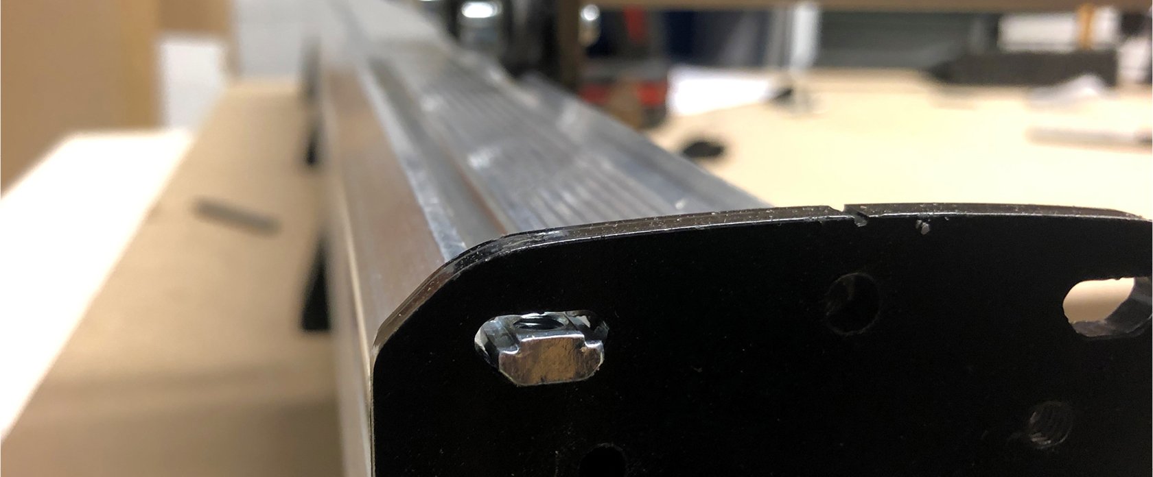
On the X-axis the process will be repeated. Slide in a t-nut through the hole in the right Y-gantry and bring it all the way to the left side next to the drag chain mount where you’ll bolt in a pin-type end link. Ensure the end link is snug up against the drag chain mount (pictured).
Lastly, attach the final end link onto the Z-axis motor mount using one last bolt to the inner hole. Note the direction the link is facing.
Routing Wires
For the remaining assembly you won’t need any more of the loose hardware except for the provided wood screws and the 3D printed ACME nut covers. If you want, take a second to clean off your space and feel free to stick all the extra remains into a box for later use or maintenance on your machine.
Before we attach the drag chains back onto the end links we’ll be moving around a couple links to get the right fit. To do this, put your hands on either side of the link you want to break, then twist and pull them apart to disconnect. Set aside the remaining, unused links – they can come in use if you’re planning on upgrading to a larger sized LongMill later.
Depending on the size of LongMill you have, remove and add links to each drag chain as follows:
- For the 12×30 LongMill, remove 16 links off of the Y-axis drag chain and add 3 links onto the X-axis chain.
- For the 30×30 LongMill, remove 13 links off of the Y-axis drag chain and add 3 links onto the X-axis chain.
- For the 48×30 LongMill, remove 13 links off of the Y-axis drag chain and leave the longer X-axis drag chain at its original length.
This will make it so the chains are the correct length to travel the whole range of motion of the machine while also staying as short as possible to maximize the wire length going to the controller.
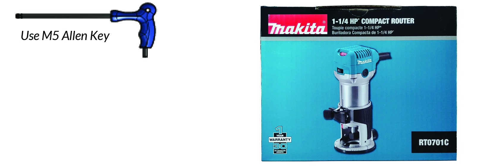
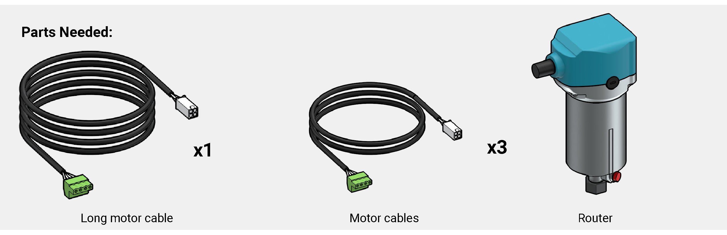
At this stage, it’s a good idea to grab the router you’ll be using with your machine. We’ll show these steps using the Makita RT0700 / RT0701 trim router, however this works for the Sienci AutoSpin as well. Also, grab the motor wires from the motor box while you’re at it.
Note: when using the Makita RT0700 / RT0701 it’ll come with a base attached. Remove this as you’ll just need the main router body for the CNC.
To mount your router, loosen off the mount’s front bolts until it slides in. Place it through so the mount is around the middle of the router body, with the cables facing left and rotated slightly backward (pictured) then tighten back up to secure it. Go back and forth between the two bolts to keep equal clamping force and make sure not to over-tighten them.
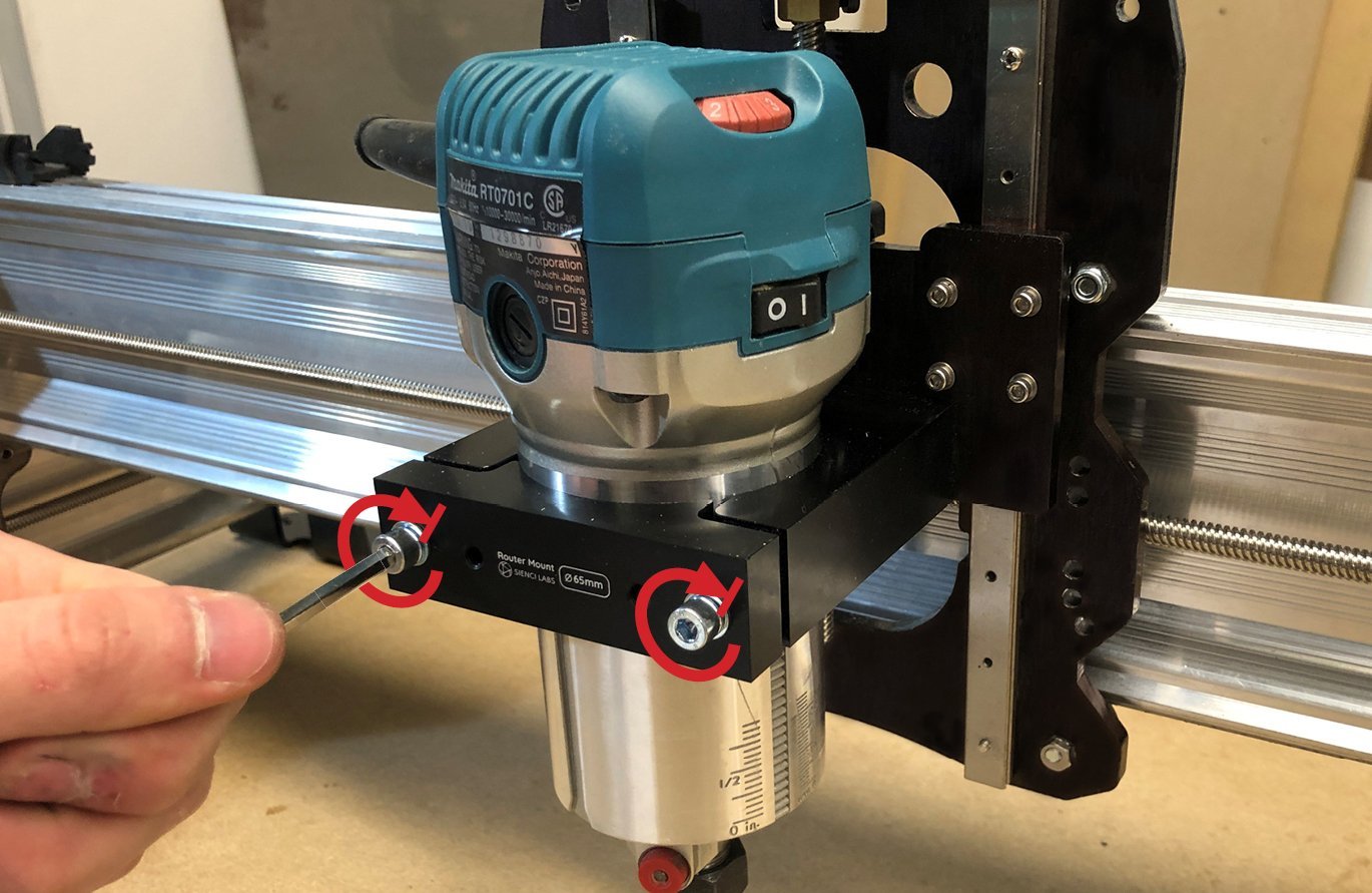
Confirm the angle by turning the Z-axis lead screw by hand until its upper limit – the top part of the router body shouldn’t collide with the Z-axis motor mount at any point. You can adjust the router height later depending on your setup: lower if you use tiny tools on thin material or higher if you use longer tools on 3-4″ thick material.
This maximum position is also where you can access the 4 bolts holding in the router mount from behind for future swapping or tramming. You’ll simply lift up the drag chain and go through the hole in the X-gantry, being mindful not to damage the aluminum rail edge with the Allen key.
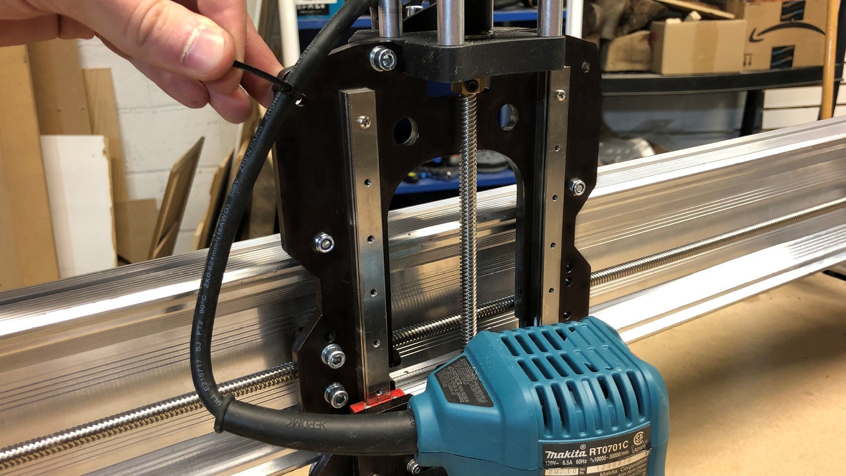
Optionally use the top left hole on the X-gantry as a zip tie point to keep your router wire out of the way during operation. To set it up right, move the Z-axis all the way down and then zip it on with some extra slack still available (pictured).
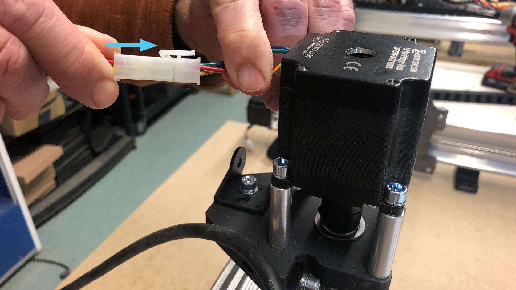
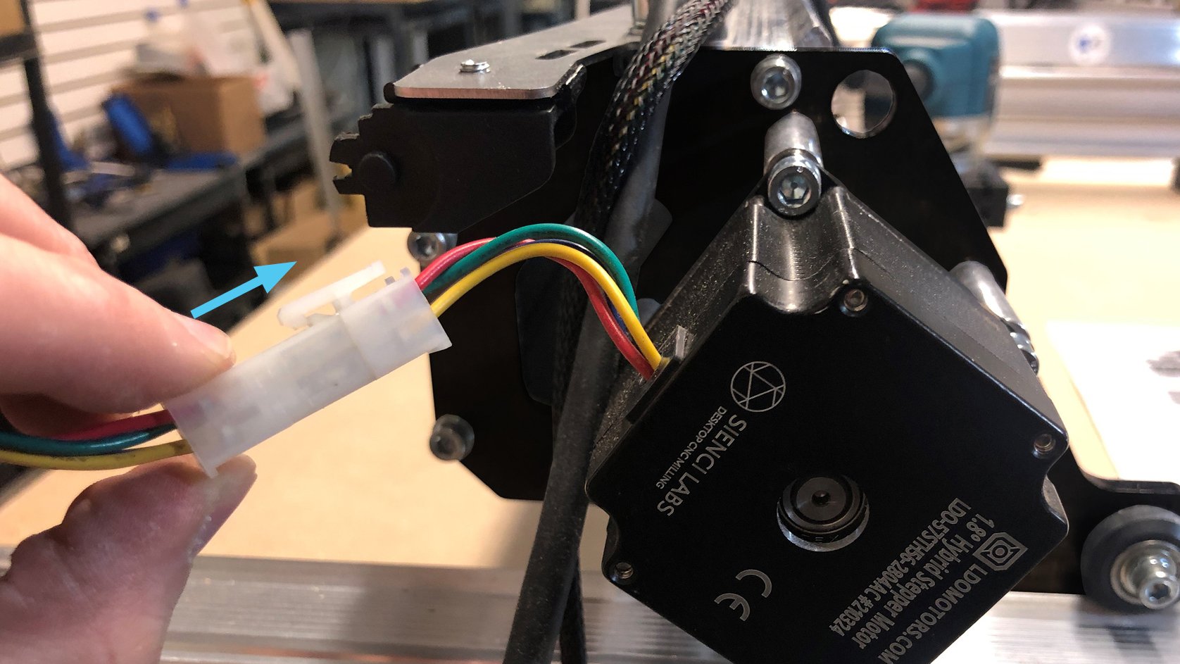
Now onto the remaining wiring. Grab the longer motor cable and connect it to the Z-axis NEMA 23 motor. The connector can only go in one way so keep trying until it easily clicks in.
Grab the drag chain for the X-axis (the longer one) and seat in the Z-axis motor cable, as well as the router power cable and signal cable (if applicable). Ensure you have the correct end of the drag chain so it’ll attach onto the Z motor mount end link and bend in the right direction. Reattach it onto the end link, then start to resecure the clips.
Note: if you purchased the limit switch add-on kit you’ll want to leave enough clips open that running the wires for the switches later on will be easier to do.
Leaving the last few clips open, bring the other end of the drag chain around and attach it onto the other end link on the X-axis rail. Pull the wires through and around the drag chain mount and finish closing the remaining clips.
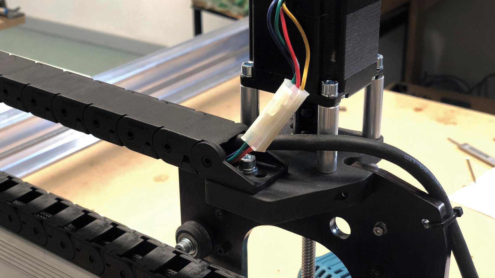
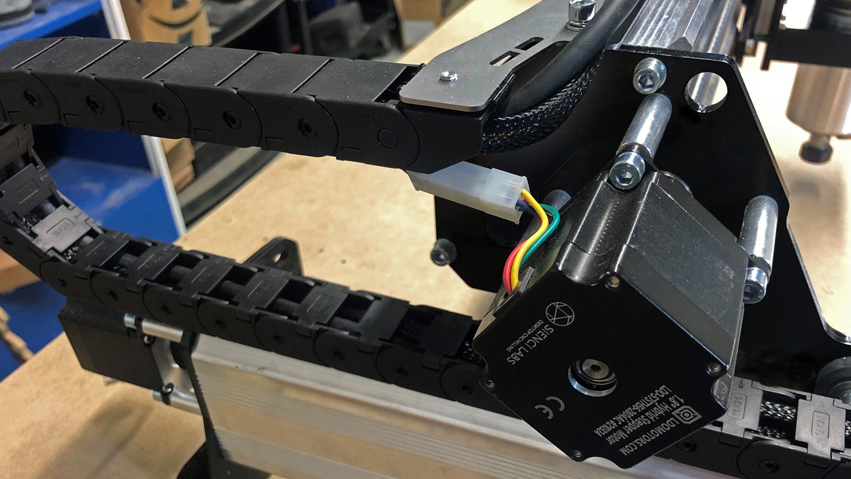
Attach a motor cable onto the X-axis NEMA 23 stepper motor. ![]()

Take the X and Z-axis stepper motor cables and the router cable and insert them into the Y-axis drag chain. Keep in mind the bend of the drag chain and attach it, clipping in the clips to secure the wires.
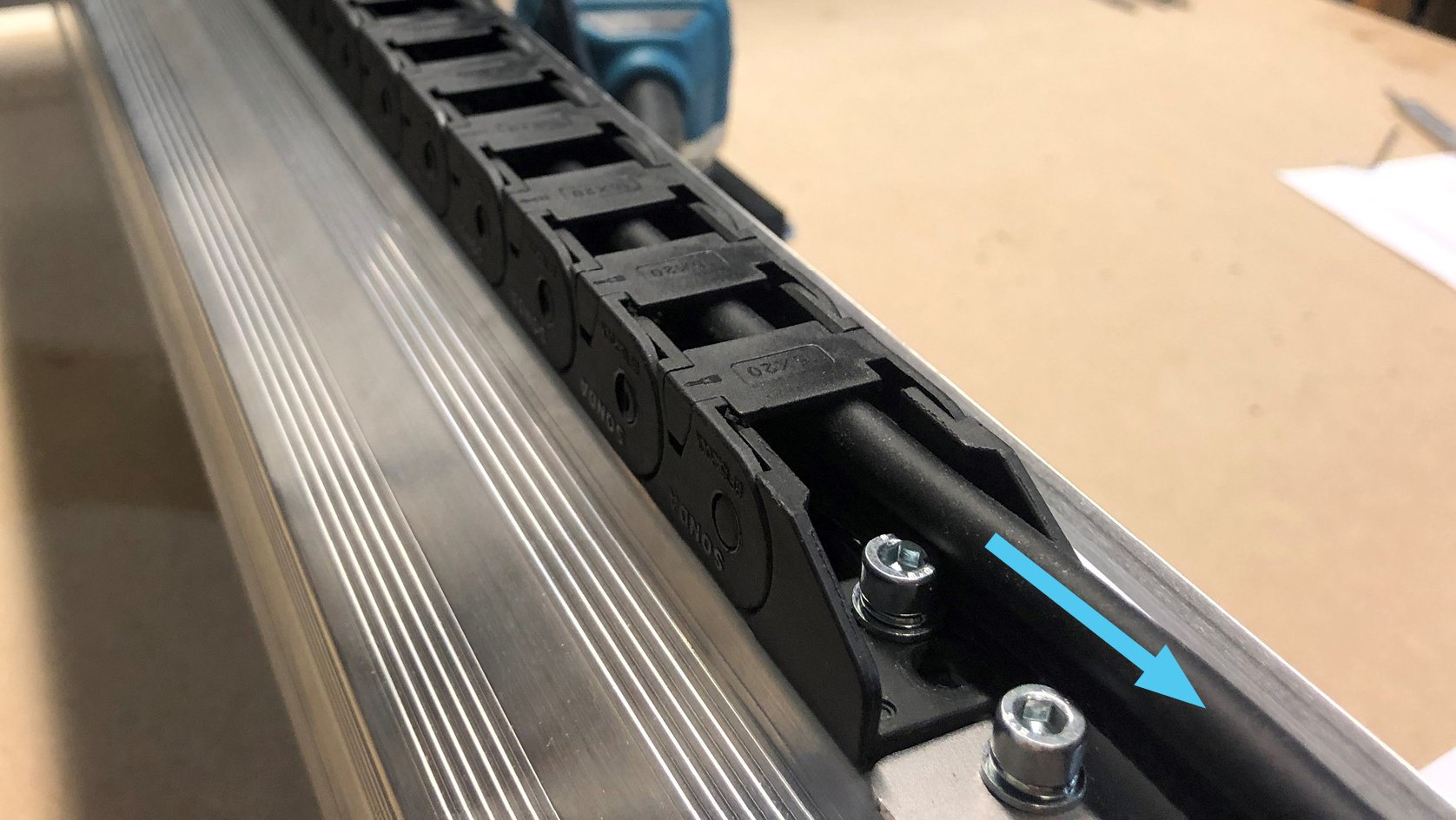
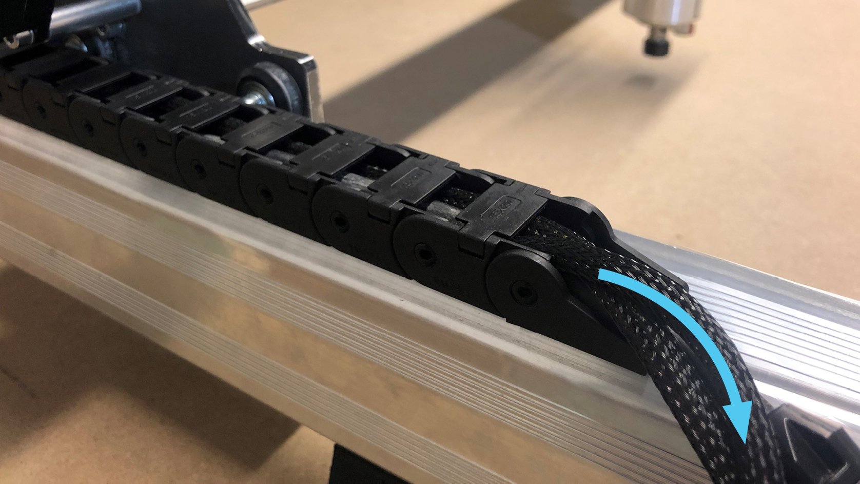
Bring the other end of the drag chain around and attach it onto the other end link on the Y-axis rail. Pull the wires through and off to the left side of the rail and close the remaining clips.
Lastly plug in the cables for the motors on the two Y-axis NEMA 23 stepper motors.
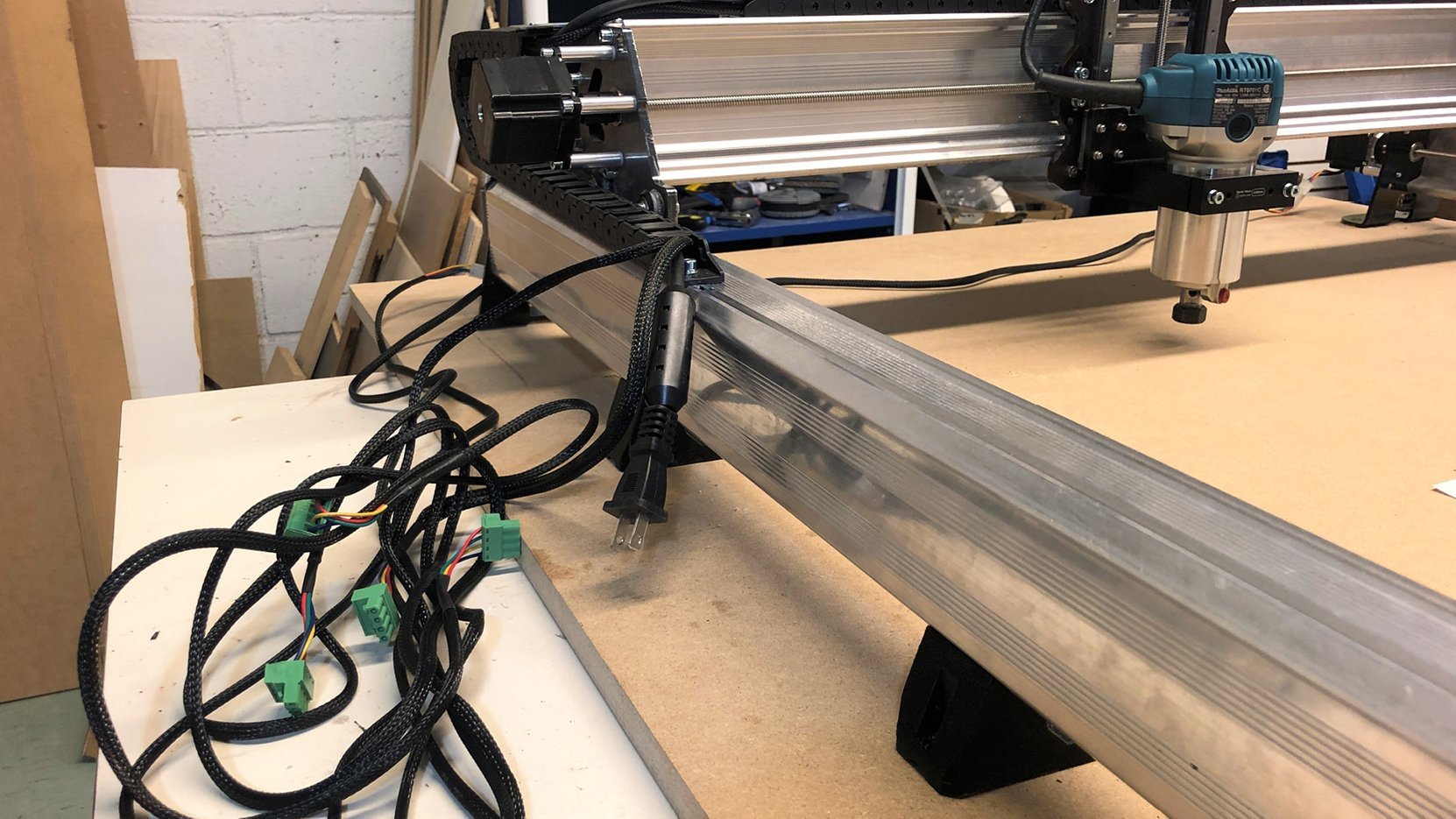
Bring the cables around to the left of the machine so they’re now all bundled together (pictured). You’ll be plugging the motors cables into the control box shortly but otherwise the machine wiring is now complete!
If you have an AutoSpin router, we recommend that you use the router in manual mode until you are familiar with your CNC. You can then switch the router over to Spindle Mode with automatic start/stop and RPM control by following the instructions here.