Nut Assemblies

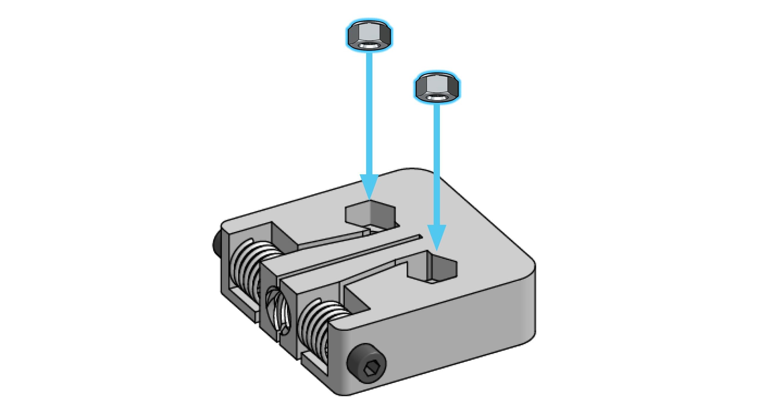
Now, find bags labelled for ‘M5-nylock nuts’, (there should only be 4 or 5 in the bag), and the final one which contains some large rectangular plastic blocks. These are called ‘T8 spring loaded anti-backlash nuts’, and you’ll see later how they work to give your CNC movement and keep it accurate.
Start by pressing the M5-nylock nuts into the hexagonal cutouts in the plastic blocks. It’ll be tempting to face the round part of the nut downwards for easier installation, but these have to actually face upward out of the plastic so that they can be properly bolted on later. It may require some force to push the nuts into the cutouts – feel free to use pliers, one of the steel plates, a vise, or anything else to get them in-place as long as you’re careful to take your time. You’ll need 4 blocks, set aside spares as extra.
With four blocks ready, set them aside.
Z-axis Motor Mount

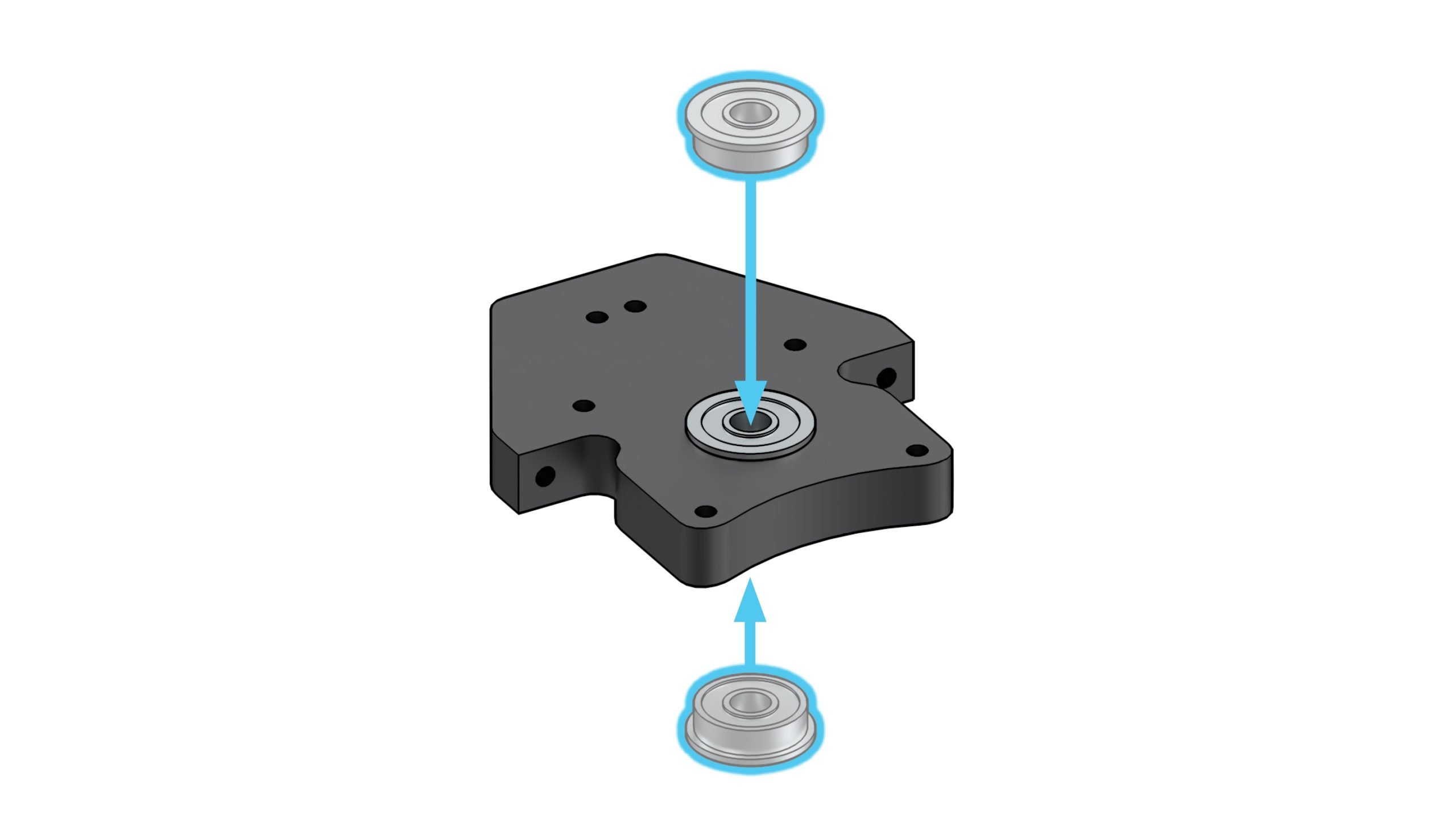
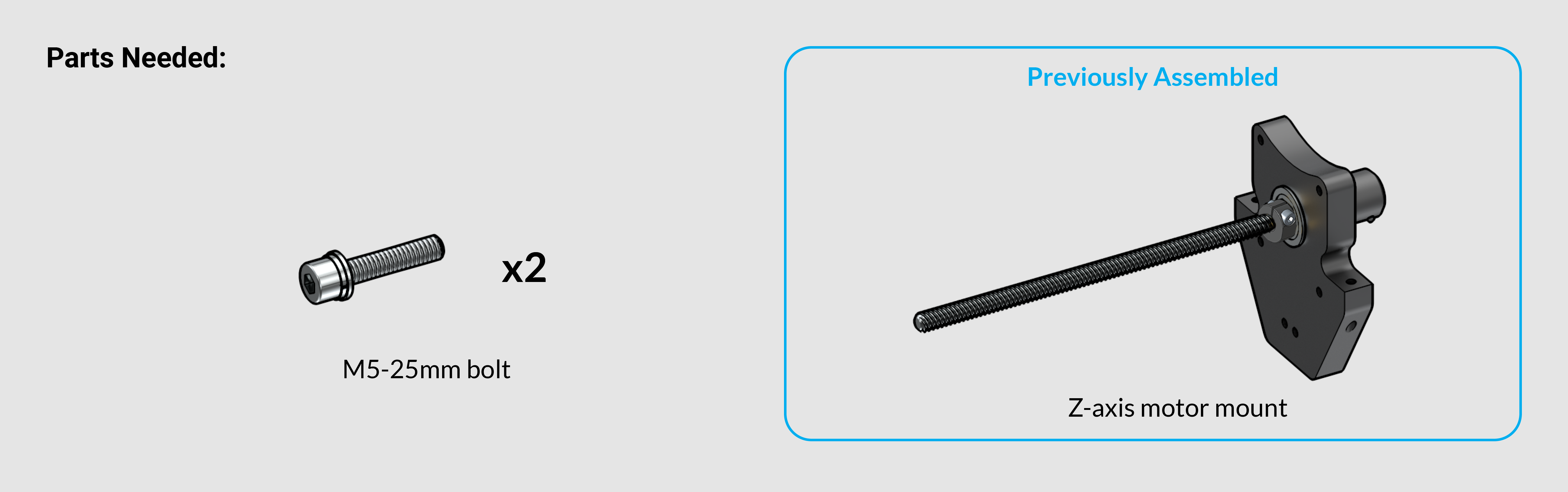
With the prep out of the way, let’s continue on to the overall XZ-axis assembly. First you’ll want to get your Z-axis motor mount from where it would’ve been kept with the rest of the cutting tools and add-ons, we call this box the ‘variable box’. It’ll be a wrapped aluminum part similar in size to the router mount.
With this in hand you’ll also want to get the bag with bearings in it, of which you’ll just need two for now. Press these into both sides of the bore on the Z-axis motor mount. You should be able to assemble these easily with your thumbs.
Z-axis Mount Sub-assembly
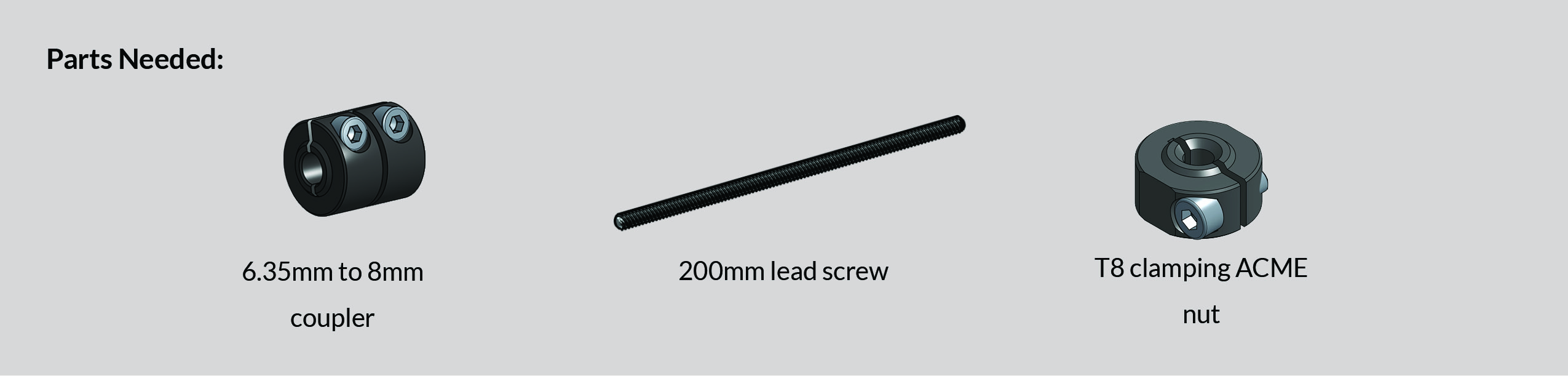
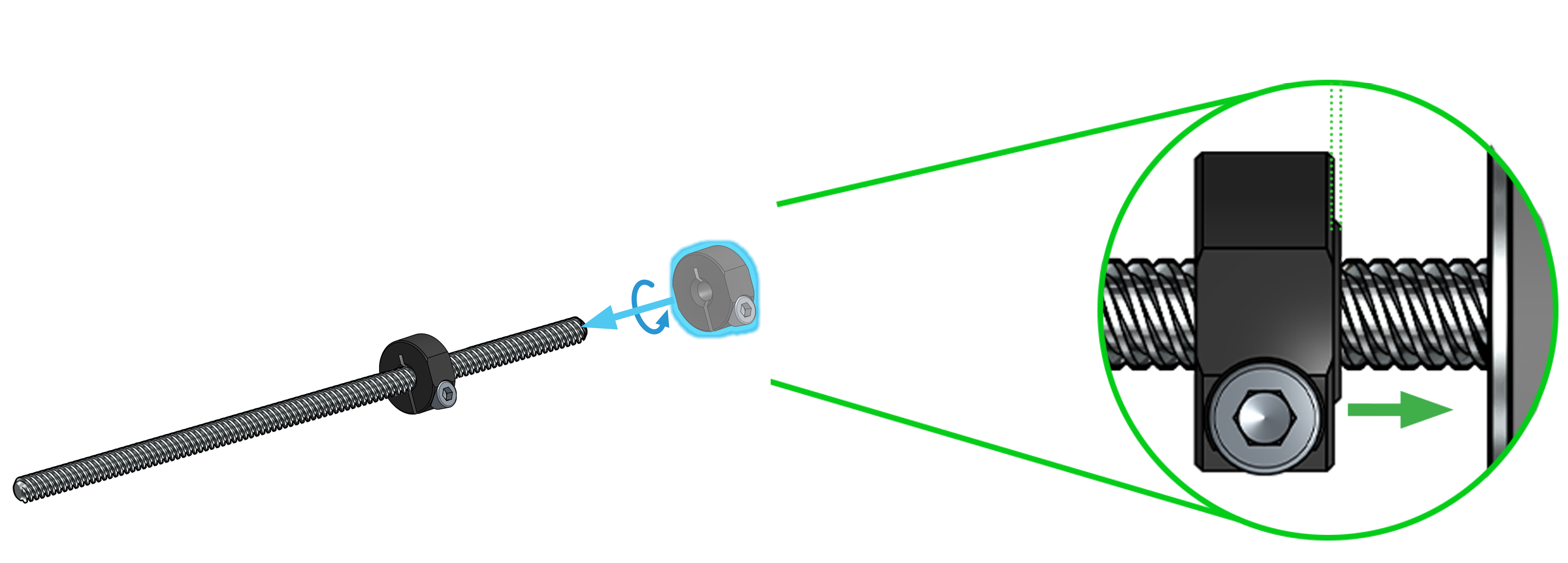
Going back to the parts, you’ll want to look for the short lead screw which will be packaged alongside the other, longer lead screws. This step will also use a locking ACME nut and a coupler from the bag of couplers. Grab the ACME nut and thread a couple inches (as pictured) onto the lead screw. Make sure the ACME nut still has its set screw.
Please Note: There is a small bump coming out of one side of the clamping nut, that will need to face towards the short side of the lead screw.
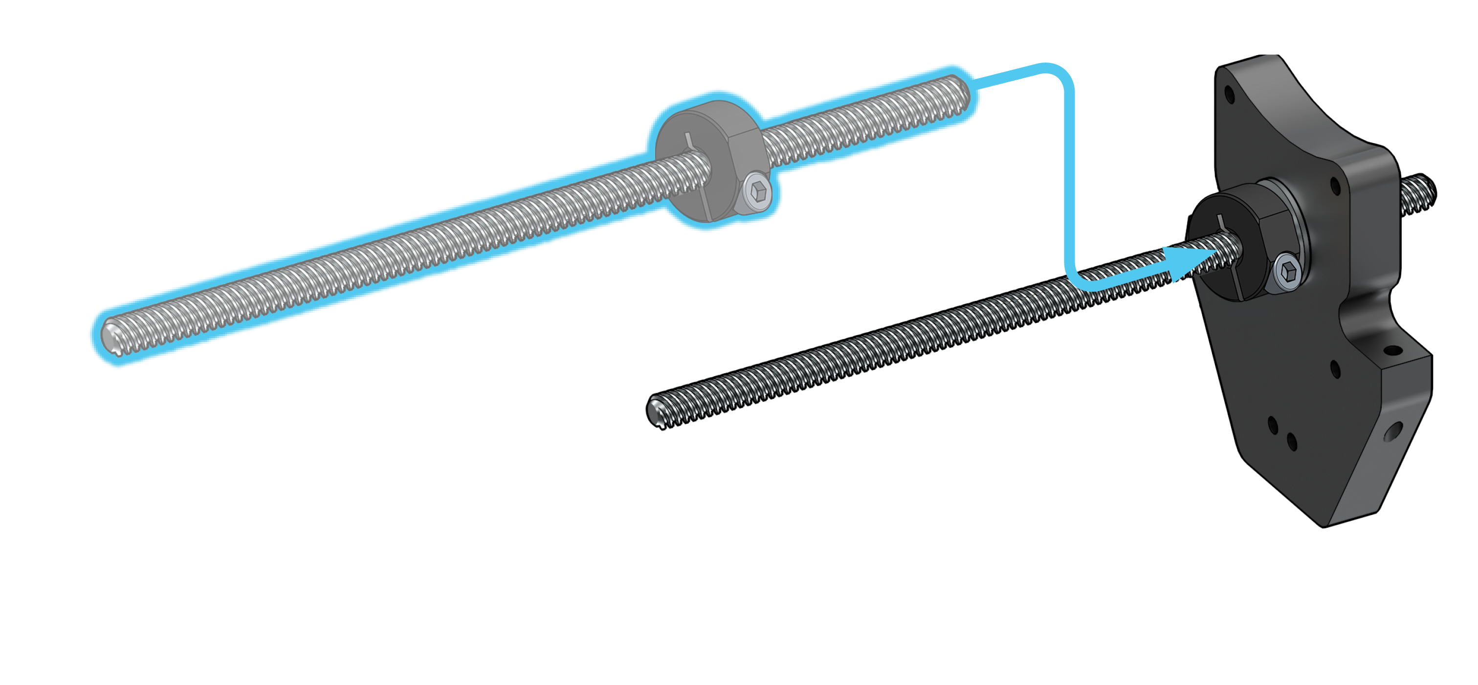
Next, slide the short end of the lead screw through the bearings on the Z-axis motor mount. This fit may be tight so just do your best to hold everything in place and try to wiggle the lead screw or tap it with a mallet if needed. Make sure the bearings are sitting straight in the bore before applying force.
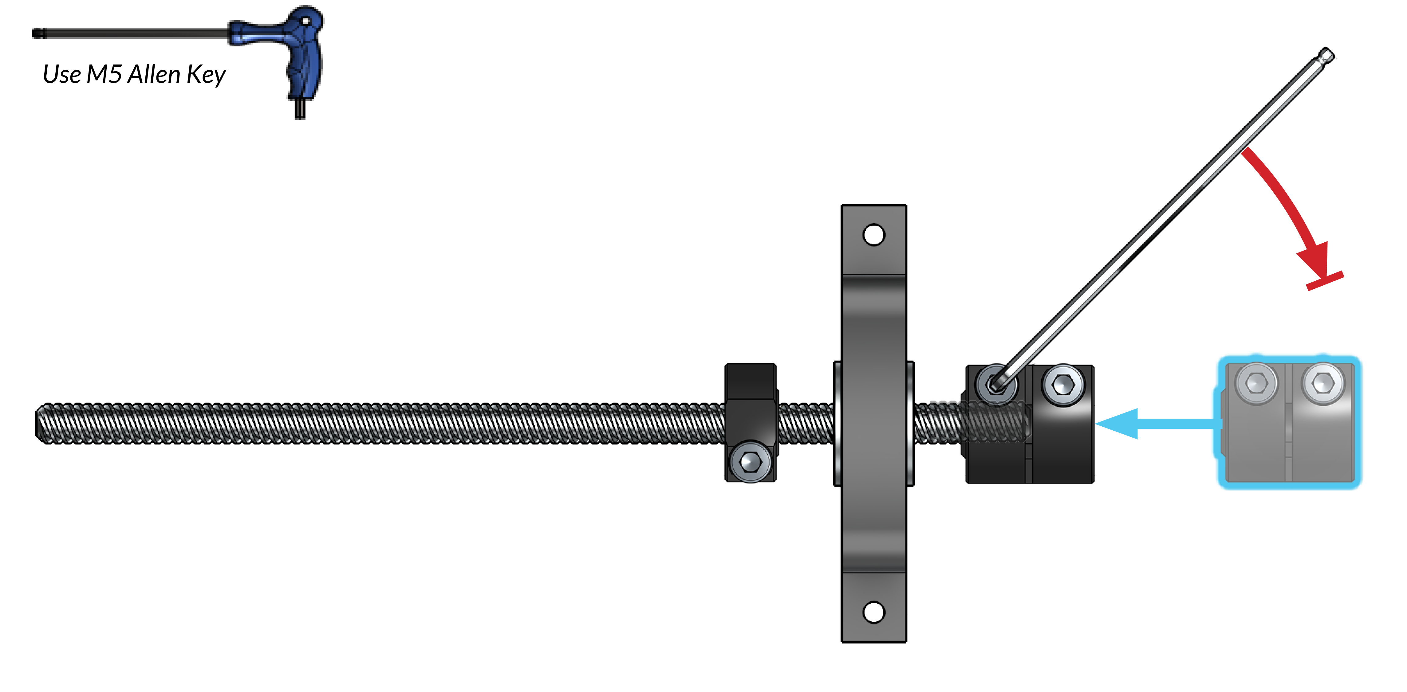
On the coupler, identify the end with the larger hole – this will be the only side that fits onto the lead screw. Push the coupler on until it bottoms out, then tighten the ‘lead screw side’ set screw using an M5 Allen key. BEWARE! Only tighten ONE of the set screws – the one on the lead screw side (as pictured). You’ll tighten the other set screw near the end of machine assembly. If you overtighten the wrong set screw it can deform your coupler and cause assembly issues.
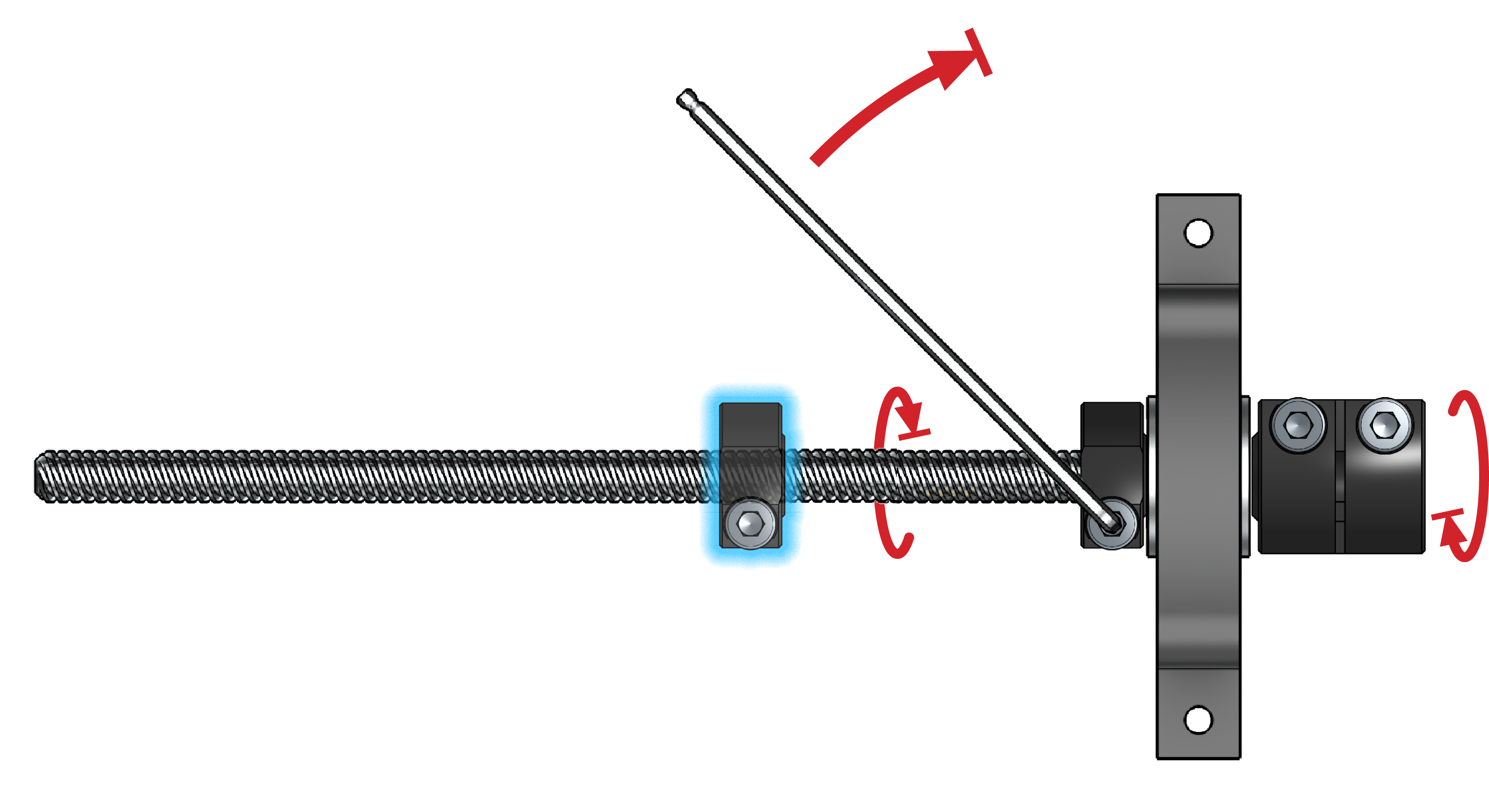
Now rotate the coupler and ACME nut in opposite directions so that they come together to clamp onto the two bearings. Once they’re together, making a ‘bolted sandwich’, everything should be touching (as pictured). Once in this position, tighten the set screw on the locking ACME nut. If assembled properly, this should now feel like a solid, single piece where the lead screw should only be allowed to rotate, and not move in-and-out. Set this assembly aside for now.
XZ-axis Gantry Sub-assembly
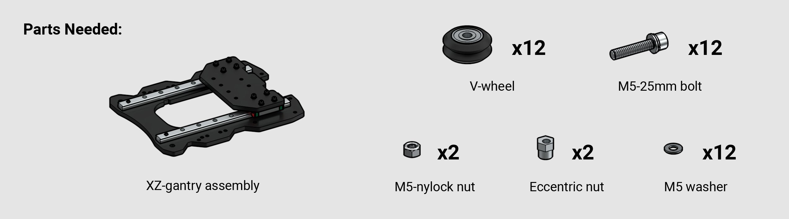
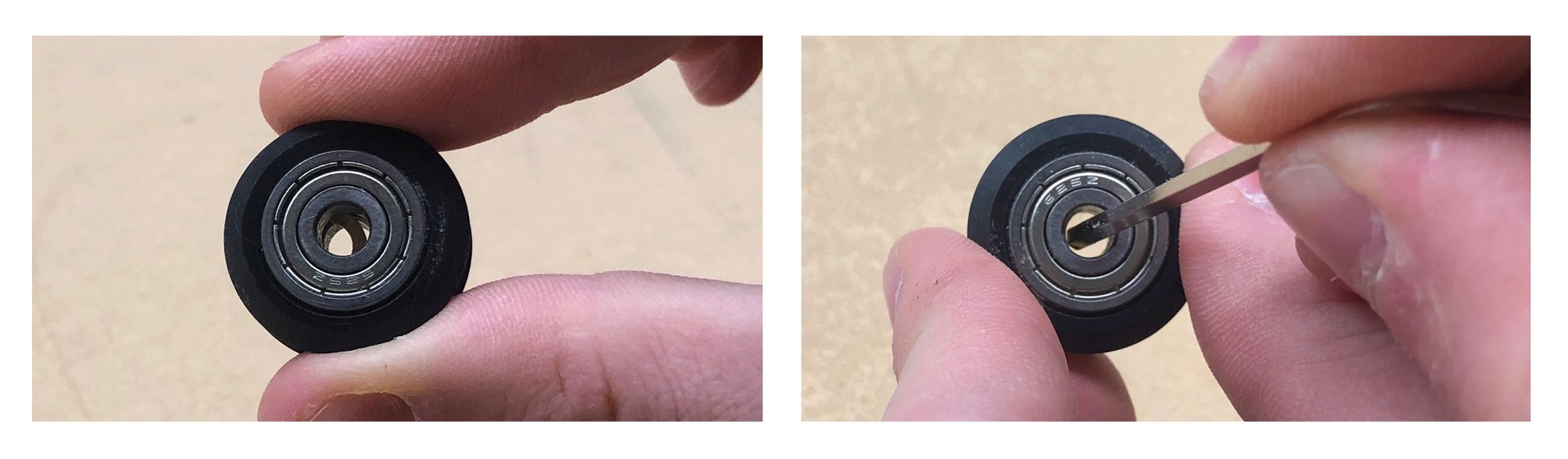
From the green bag, grab the ‘M5 washers’, ‘M5-25mm bolts’ and the ‘Delrin V-wheels’. If the v-wheels have an off-centered ring in the middle (pictured), use the small Allen key to move the ring back to the center.
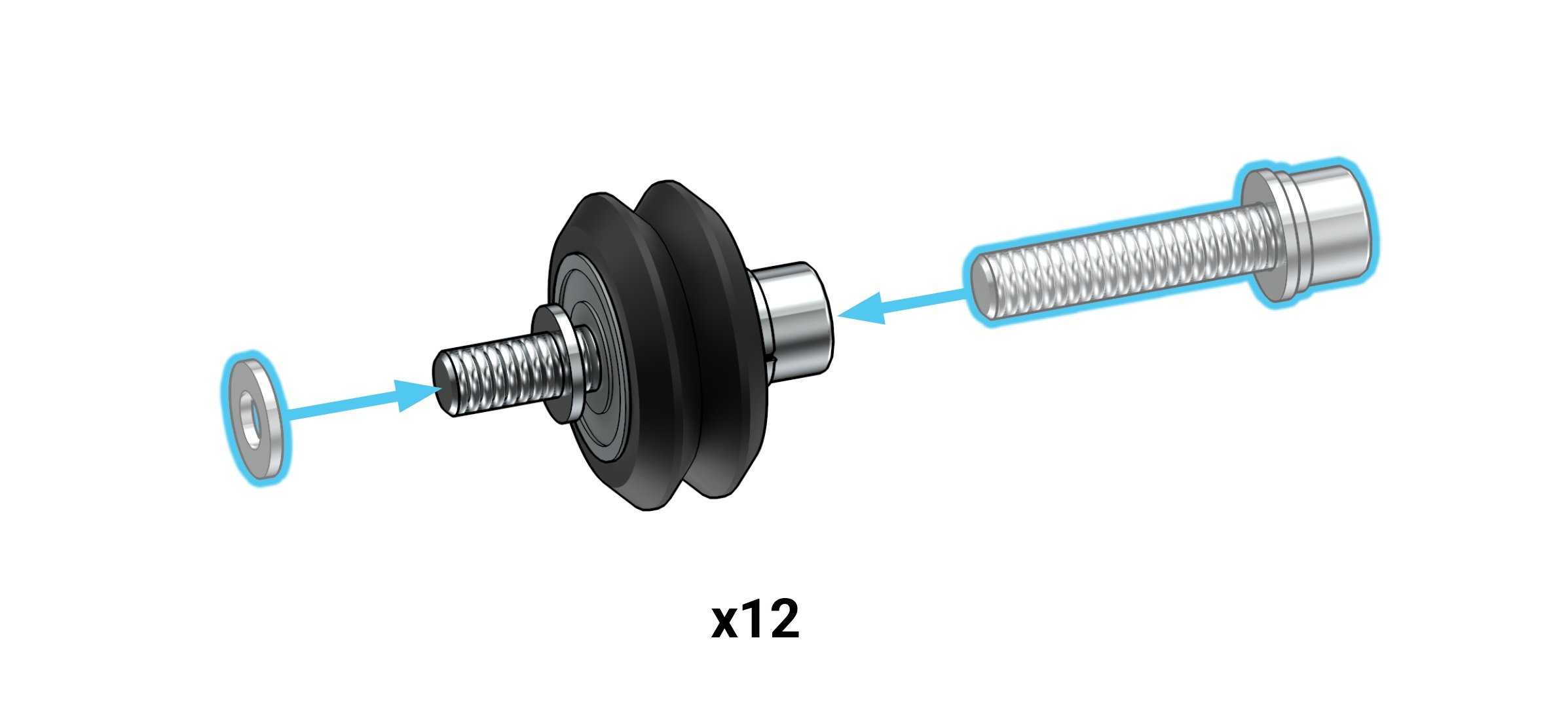
Using all 12 v-wheels, put the bolts through each with a washer on the other end. Ensure the washer is in the correct place, because this keeps the wheel from rubbing against the gantry and provides the correct spacing between the gantry and the lead screw.
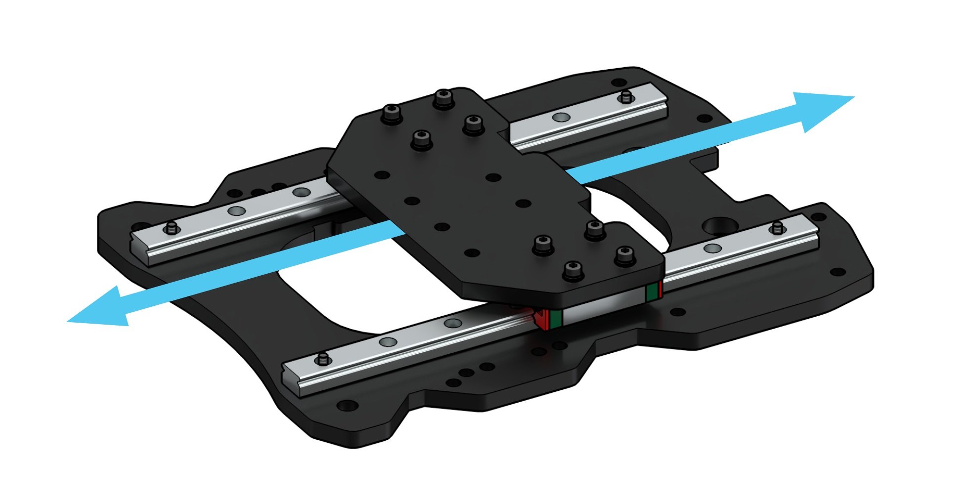
You should now find the XZ-gantry assembly among the cardboard wrap of the steel gantries. This looks like a smaller steel plate (Z-gantry) attached to a larger steel plate (X-gantry) via two sliding rails (pictured). First, check the movement of the Z-gantry by moving it up and down with your hand. The motion should be smooth, and there should not be any binding. The existing bolts going into the front and back of the plates should also already be reasonably secure but not fully torqued down.
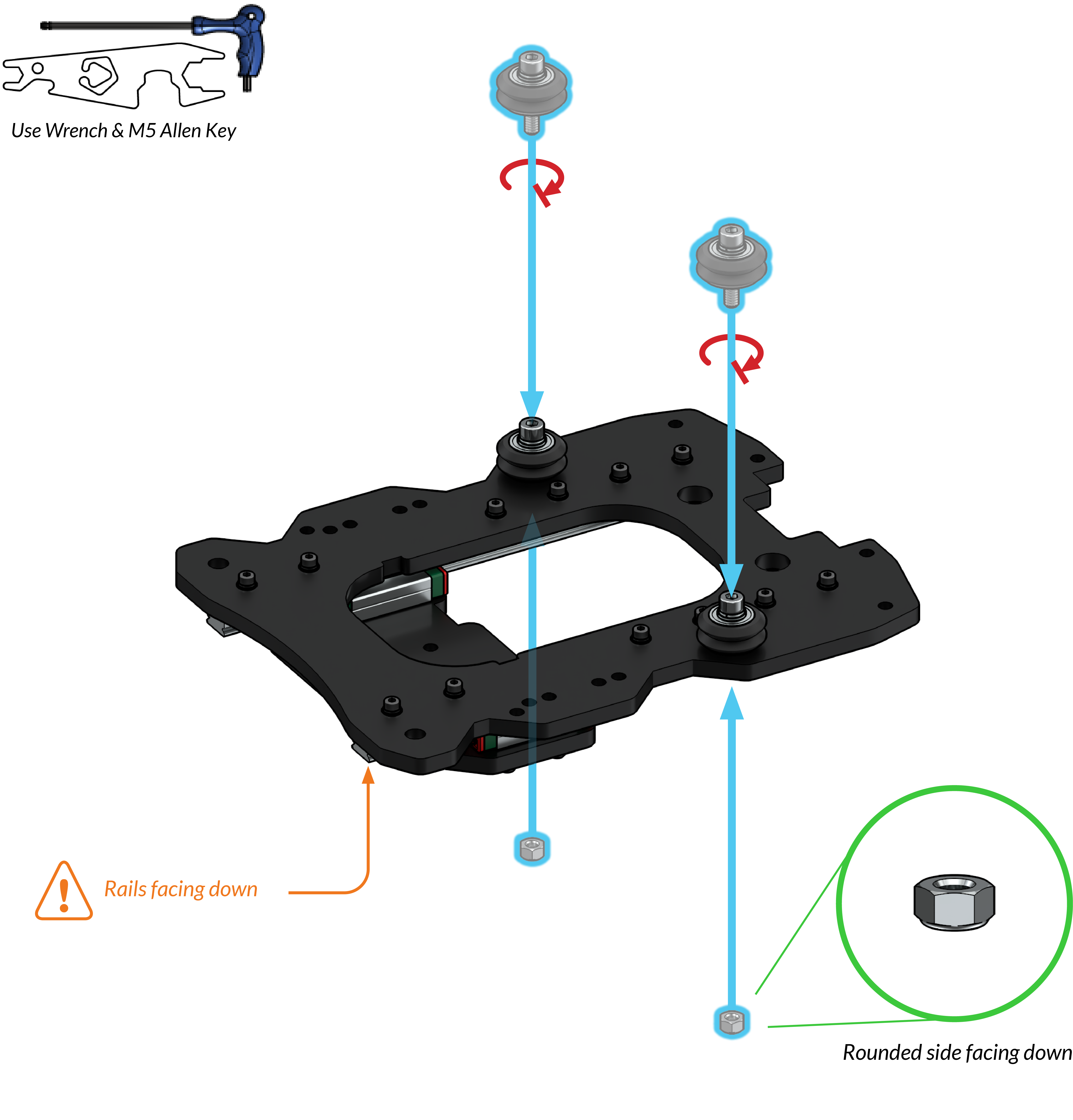
Install two of the v-wheel assemblies onto the XZ-gantry assembly with two nylock nuts. Use the included wrench to keep the nuts in place, while you use an M5 (size 4) Allen key to tighten the v-wheels. The rounded end of the nylock nuts should face away from the gantry. Ensure that the nylock nuts are firmly secured.
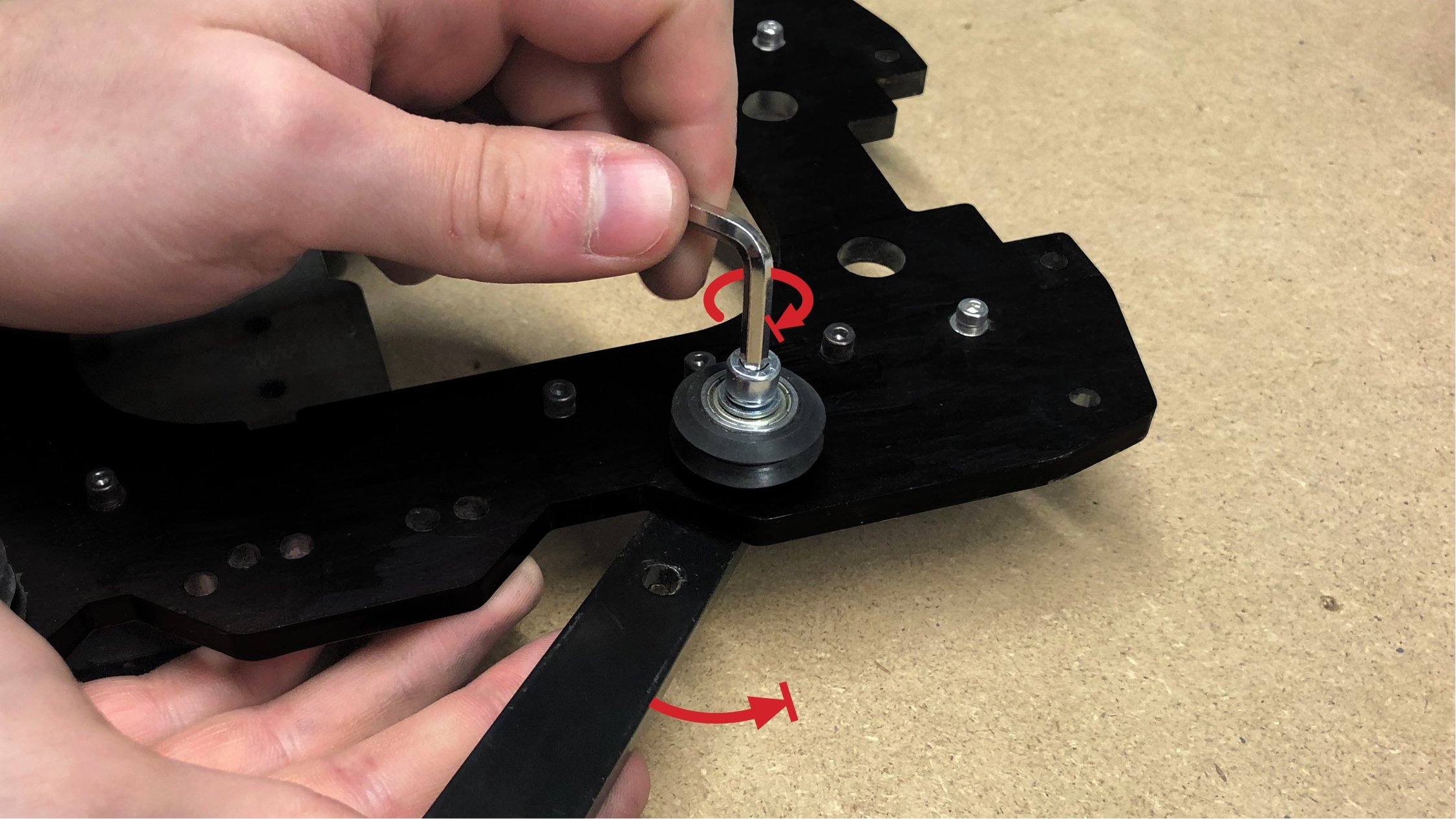
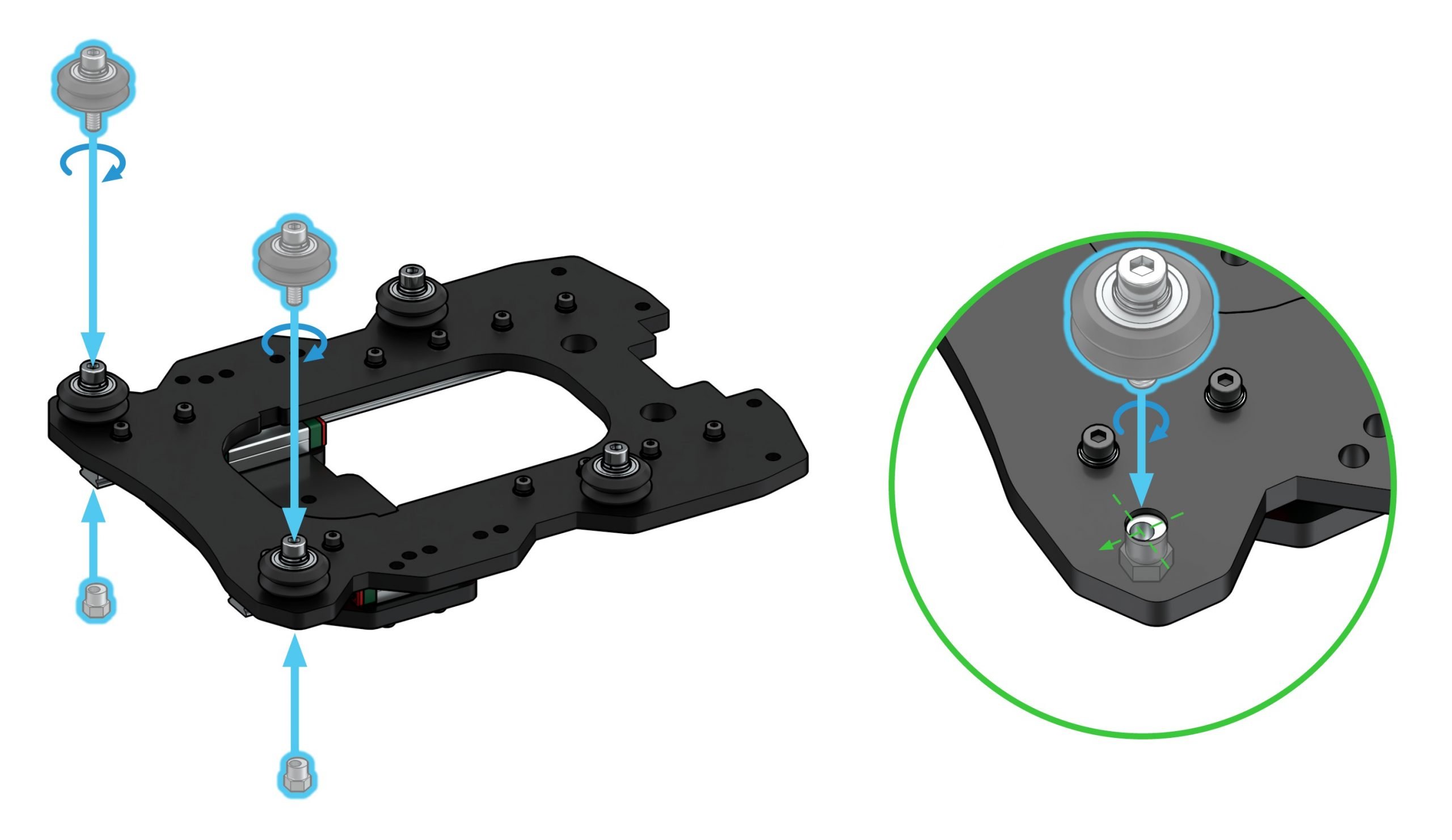
Install two v-wheel assemblies at the bottom edge of the gantry – except this time, use two eccentric nuts. When placing the eccentric nuts inside the gantry holes, ensure the inner holes of the nuts are oriented towards the bottom edge of the gantry (pictured). Use the included wrench to keep the nuts in place, while you use the Allen key to loosely attach the v-wheels.
Attaching Anti-backlash Nuts

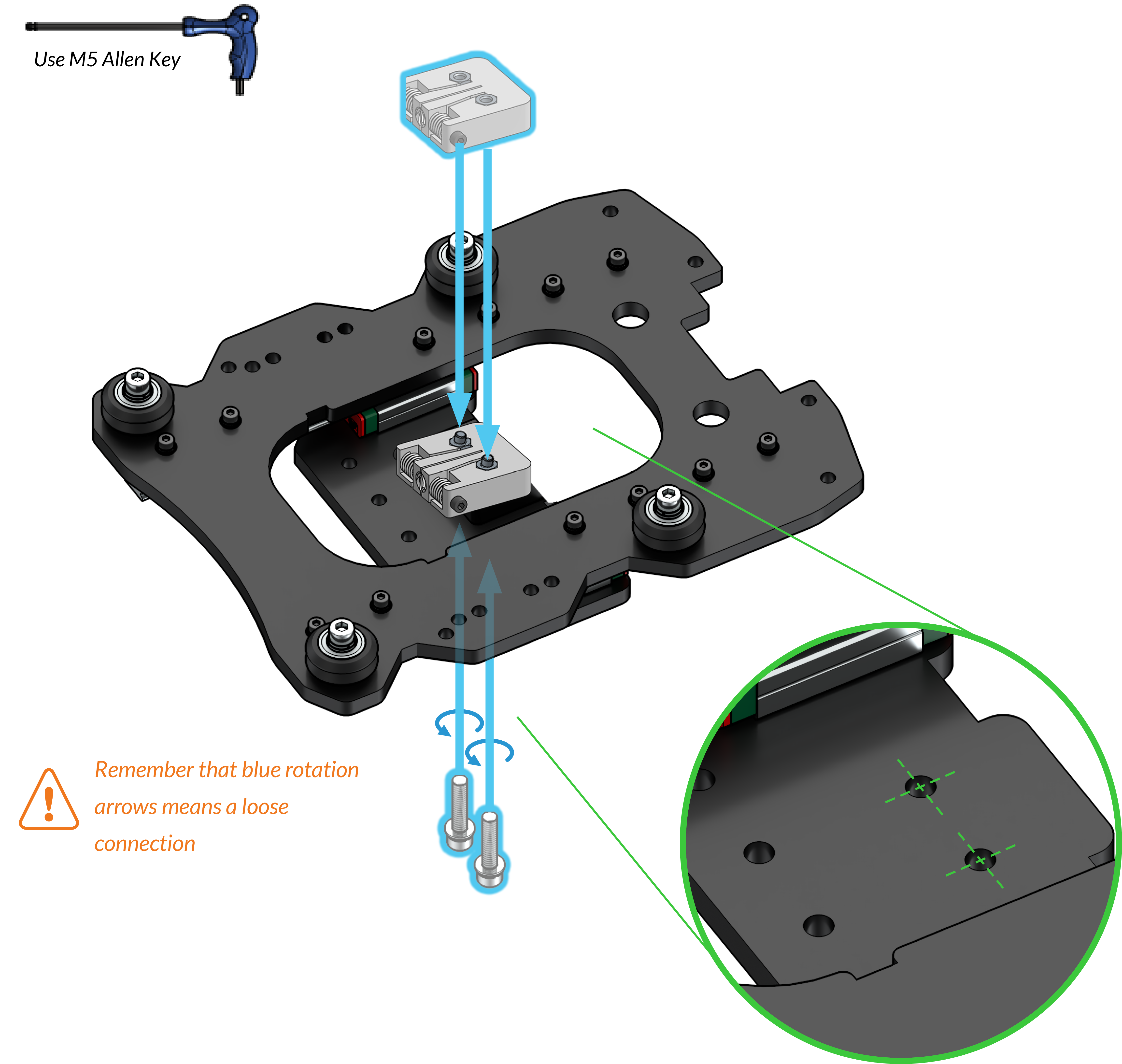
Using two M5-25mm bolts, loosely attach one Delrin anti-backlash nut to the back of the sliding Z-gantry. Make sure to use the two holes near the notch on the gantry (pictured).
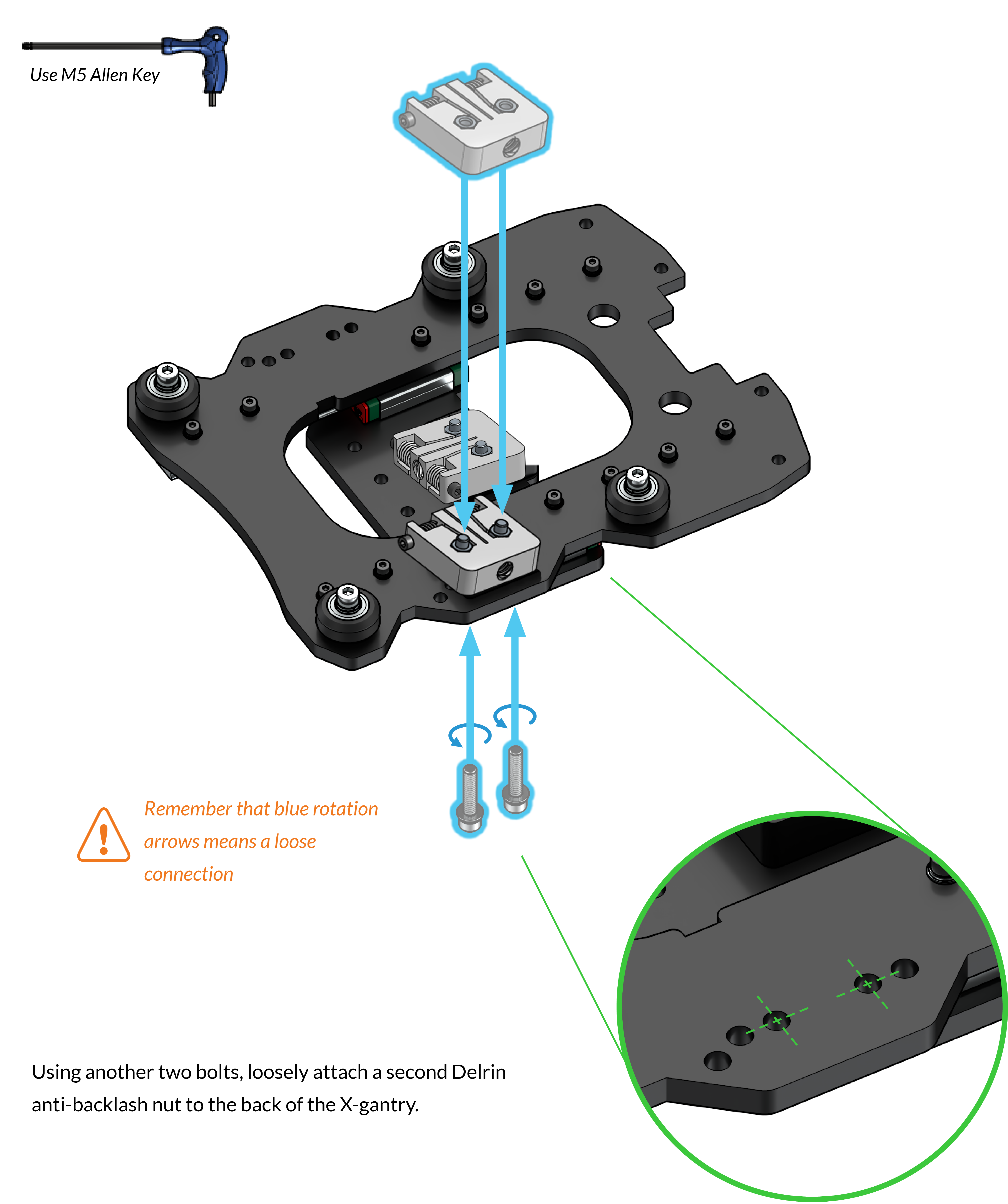
Using another two bolts, loosely attach a second Delrin anti-backlash nut to the back of the X-gantry. ![]()

Connecting the Sub-assemblies
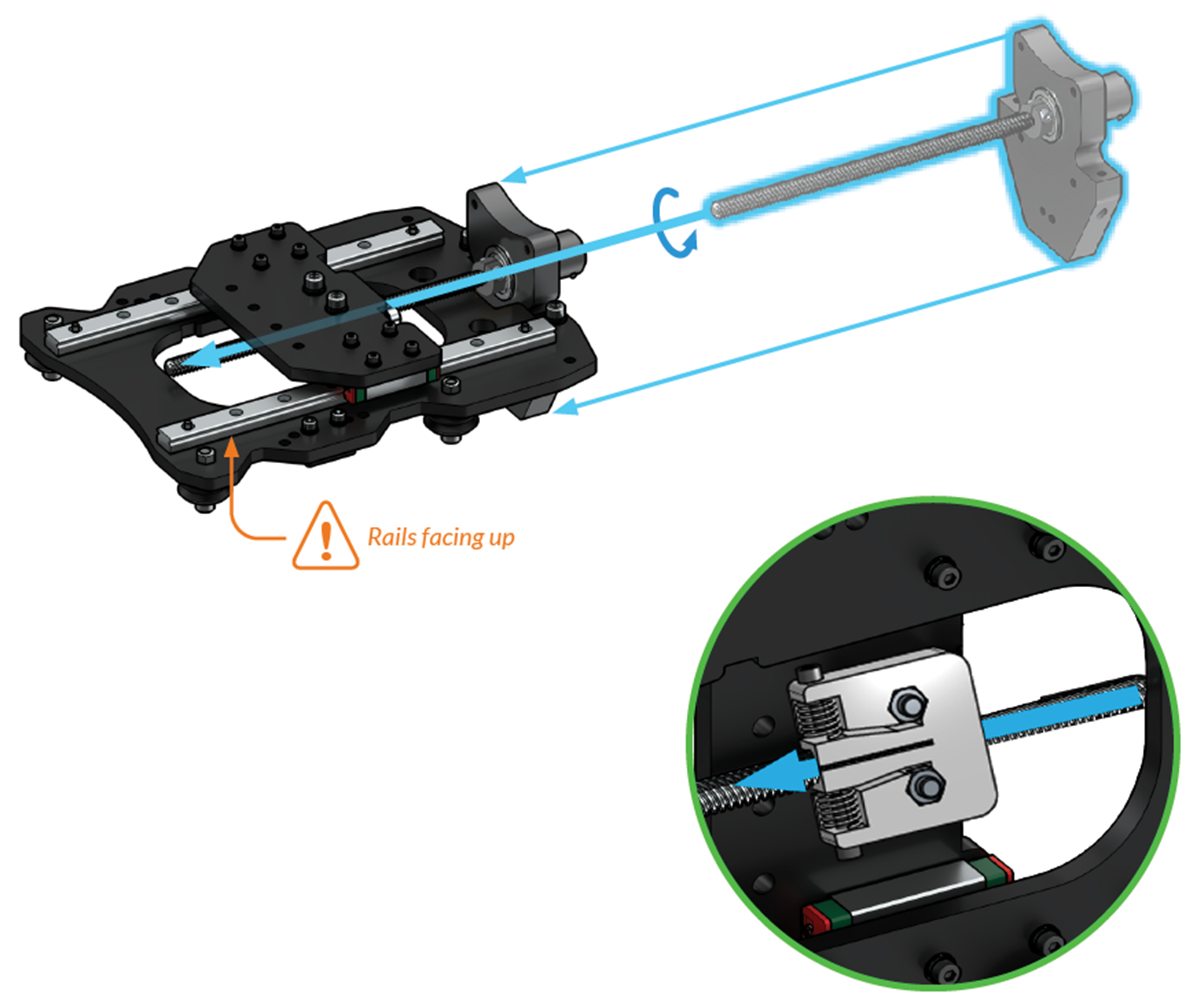
Slide the Z-axis motor mount onto the XZ-gantry assembly, checking that the orientation is correct (pictured). Thread the lead screw into the Z-gantry anti-backlash block between the two steel plates.
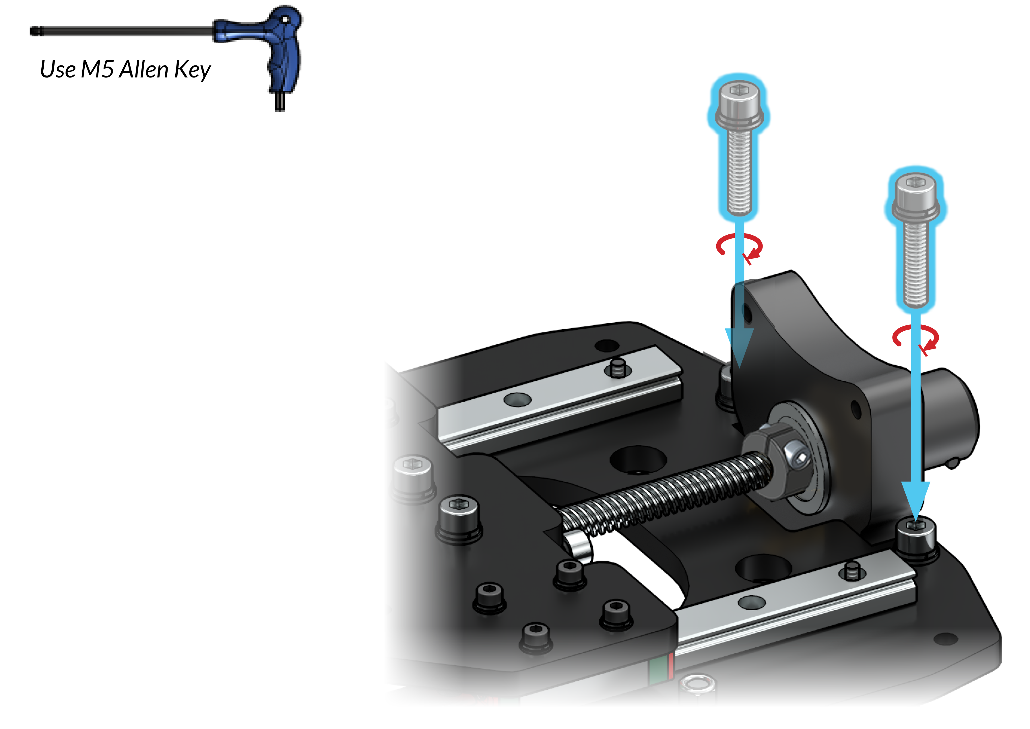
Fasten two M5-25mm bolts on both sides of the Z-axis motor mount to secure the two assemblies together.
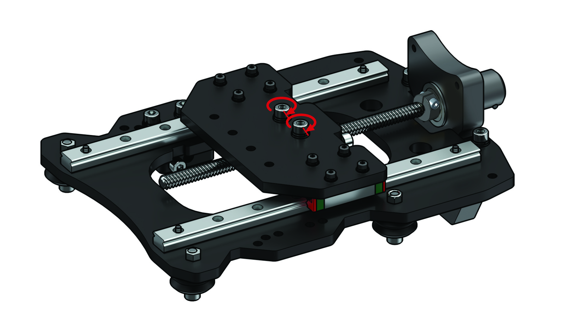
With everything secured together, you can finish tightening the two bolts holding the Z anti-backlash nut. Alternate making a couple turns onto one bolt and then the other until they’re both tightened down. If you twist hard onto just one bolt while the other one is loose it can twist the anti-backlash nut and misalign it to the lead screw.
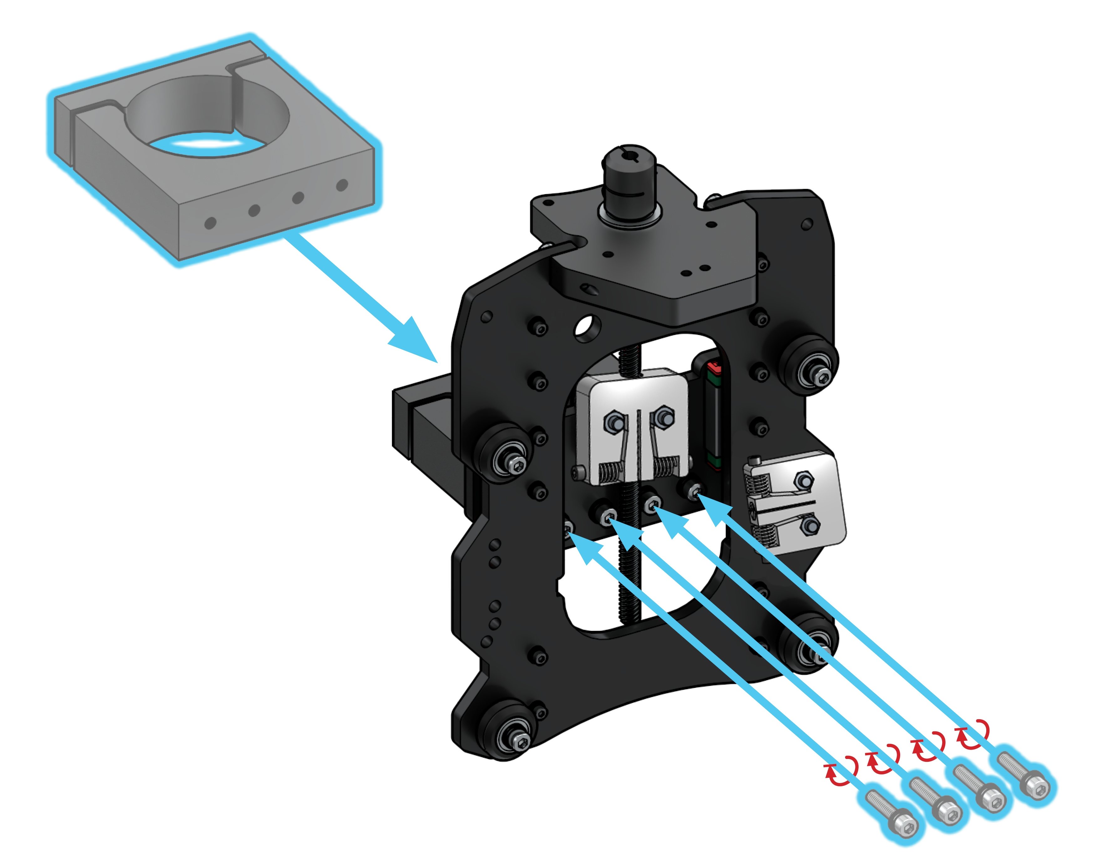
Attaching the Router Mount

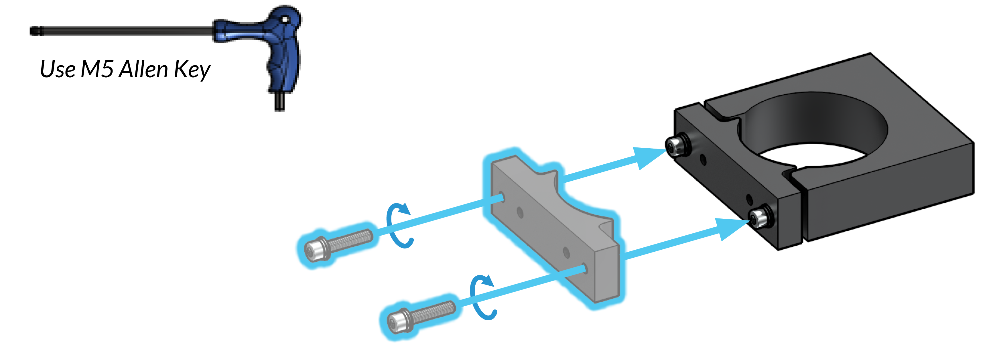
Grabbing the router mount from the ‘variable box’, loosely attach the front using two M5-25mm bolts, then bolt the mount to the XZ-gantry assembly with another four M5-25mm bolts. Ensure the bottom of the router mount is flush with the bottom of the Z-gantry.